Presented and Published as part of the Eurographics UK 1996 Conference, Imperial College, London.
A Data Decomposition Tool for Writing Parallel Modules in Visualization Systems Steve Larkin, Andrew J Grant, W T Hewitt Computer Graphics Unit, Manchester Computing University of Manchester, Manchester M13 9PL, UK. Tel: +44 161 275 6095, Fax: +44 161 275 6040 Email:
[email protected],
[email protected],
[email protected]
Abstract The aims of the “Visualization in Parallel” (Vipar) project is to produce a comprehensive environment for the development of parallel visualization modules in systems such as the Application Visualization System (AVS), Iris Explorer, IBM Data Explorer (DX) and Khoros. This paper presents an overview of the project and will describe the data decomposition tool and libraries developed during the first phase of the work to support the writing of parallel visualization modules. This work is funded as part of the EPSRC project (GR/K40390) Portable Software Tools for Parallel Architectures (PSTPA).
1 Introduction This paper first describes the aims of the Visualization in Parallel (Vipar) project and, as background material, an overview of the problems associated with producing parallel visualization systems. Section 2 describes the Vipar system architecture and related components. The data decomposition tool (DDTool), parallel module structure and support libraries are covered in sections 3, 4 and 5 respectively. The paper finishes with some conclusions and an outline of the future work in section 6. 1.1 Aims of the Project Current visualization systems such as the Application Visualization System (AVS) [1], Iris Explorer [2], IBM Data Explorer (DX) [3] and Khoros [4] allow users to construct visualization applications by connecting a number of modules together into a network or map. One of the key features of these systems is the ability of users to integrate their own application code into the system to perform tasks that are not supported within the standard package such as embedding a simulation code or interfacing a data acquisition device.
As these systems have become more widely used for a variety of problems researchers have moved towards parallel solutions when building applications using these systems. The main reasons being: • bottlenecks created by highly computational modules in an application • large datasets which cannot easily fit into the real memory of a single compute node. Many of the parallel solutions which have been developed to tackle the above problems have the disadvantage of being specific to the hardware and parallel support libraries being used and are application dependent. This has the effect of either rendering the code unusable for other applications, or too time consuming to change. The aim of the Vipar project is to provide a software environment to support users who are developing parallel modules for use within applications constructed using current visualization systems. The tools support the generally used schemes for implementing these modules and insulate users from the underlying hardware and support libraries. The phases of the project include the development of: • a data decomposition tool to generate templates for parallel modules;
A Data Decomposition Tool for Writing Parallel Modules in Visualization Systems: Page 1
April 1996
Presented and Published as part of the Eurographics UK 1996 Conference, Imperial College, London. • a network editor for building and managing parallel visualization applications. The environment will be portable between networks of workstations and Massively Parallel Processor systems (MPP) and made available for both virtual shared memory and distributed memory parallel machines. To achieve this aim it is implemented using Message Passing Interface (MPI) [5], [6] and Pthreads [7].
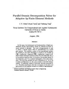
or parallel communication (see figure 1C). This is sometimes referred to as inter module parallelism. There are a number of issues relating to the development of parallel systems and some of these are summarised below. A more detailed discussion can be found in [15]. Dataflow
1.2 Background There has been some work carried out by various research groups to exploit potential parallelism in visualization systems. This can be catergorised ([8], [9]) into three classes. A. Functional/Task: a number of modules in the system can be executed concurrently on separate processors within machines (see figure 1A). Most of the current application builders provide a facility to support the execution of modules on other remote heterogenous machines with the visualization systems handling the communication and data transfer. This is a coarse grain solution as each individual module is still executed sequentially. B. Parallel Modules: this approach targets the most computationally expensive modules in an application and parallelises/vectorises them for specific platforms (see figure 1B). The problem with this approach is that the data distribution and resulting composition of results carries an overhead and can sometimes outweigh the performance speedup gained. This is sometimes referred to as intra module parallelism. Most of the current visualization systems do not directly support this style of parallelism but there are many examples of work in this class [10], [11], [12], [13], [14]. One exception is the IBM Data Explorer [3] which provides supports for data parallelism with no interdependencies (read only) between the individual data partitions being processed. This scheme is currently supported on symmetric multiprocessor workstations. C. Parallel Systems: The application is constructed in a visualization system which has been developed to support and handle parallel modules. Interaction between parallel modules is managed by the system and communication between individual modules is performed through the sharing of data
Sequential modules
A
Parallel Modules
C
Parallel Comms
Distribution Modules executing on different processors Composition Sequential modules
B Figure 1: Exploiting potential parallelism 1.2.1 Issues relating to Parallel Systems Data Decomposition: there is a requirement to reduce or eliminate the unnecessary data composition and redistribution between modules and to take advantage of parallel communications or the sharing of data. Synchronisation: The dataflow paradigm on which the visualization systems are based restricts modules in the network to only start processing when the complete dataset is available from an earlier stage. Typically in most datasets there are regions where less processing is required and in a parallel visualization application these portions could be passed onto later stages in the network. This can be counteracted if the processed portion requires data from its neighbours before the next stage can be started. If a number of time steps or stages of a simulation are being processed then the system needs to ensure it has a method of correctly grouping the portions when they reach the final stage. Mapping: the mapping of processes to physical machines (in a Network of Workstations) or a group of processes within a single environment (MPP) needs to addressed. An important factor in this decision is the provision of feedback on per-
A Data Decomposition Tool for Writing Parallel Modules in Visualization Systems: Page 2
April 1996
Presented and Published as part of the Eurographics UK 1996 Conference, Imperial College, London. formance monitoring to allow both the user and system to perform load-balancing. There has been some earlier work on developing complete parallel visualization systems. The PISTON system [16] was designed to aid the development of data parallel image processing and visualization algorithms. The NEVIS project [15], [17] investigated the use of modular visualization systems in a distributed memory MIMD environment. The first phase of the Vipar project addresses the need to provide tools which aid the generation of single parallel visualization modules (intra module parallelism). It is important though that the design and implementation of the underlying libraries support inter module parallelism and allow the above issues to be addressed in the later stages of the project.
2 System Architecture Figure 2 shows the relationship between the visualization system and the Vipar tools and support libraries. DDTool Visualization System VPRvsi VPRidd & VPRdd MPI/Pthreads
VPRdd: a library of routines [22] to distribute, manage and composite data. It is used to implement the mechanisms made available in the VPRvsi. This library is system dependent. 2.1 Overview of AVS/Express and AVS6 The prototype version of DDTool has been developed for the AVS/Express programming environment [23] and AVS6 visualization system [24]. AVS/Express is designed for developers who are creating technical applications for distribution to customers and AVS6 is the next release of AVS, replacing AVS5. AVS6 is aimed towards end users who want to perform data visualization. Both AVS6 and AVS/Express share the same common architecture. 2.1.1 Object Manager The dataflow paradigm used by many visualization systems is restrictive as it means generating multiple copies of the data as it passes through the visual data analysis pipeline. This overhead is greatly increased when large datasets are being processed. AVS/Express and AVS6 have moved away from the dataflow paradigm to the idea of an object manager with modules using object references as handles to datasets. Work is underway to develop a distributed version of AVS/Express (called MP/ Express) [25] which will involve the implementation of a Distributed Object Manager (DOM) to handle the management and distribution of AVS/ Express data.
Figure 2: System architecture DDTool: A tool to automatically generate a parallel module. DDTool allows the user to describe the data decomposition strategy and other criteria when constructing a parallel module and produces a template module structure. VPRvsi: The Visualization System Interface library [21] provides an interface to the other support libraries by handling the data in the form the native visualization system uses and mapping it onto the structures used by the independent and general support libraries (VPRidd and VPRdd). VPRidd: a library of routines [22] to calculate data distribution patterns and other useful utilities. These functions are characterised as being independent of the underlying system.
2.1.2 AVS6 Module Structure A module in AVS6 is an object that has parameters and methods. Each method corresponds to a C or C++ subroutine that is called when the object is created, destroyed or when a parameter’s value changes. When a method is called it can access and modify its parameters values. The code section below shows a description of a module in AVS6 using V; V is the language used in AVS6 to define objects and applications. The module has three parameters, two of them are input parameters (ImageA and ImageB). The input parameters are defined as read only and will cause the method (update) to be invoked when they are changed. This is indicated by associating the two properties read and notify with the parameters. The third parameter is defined as an output param-
A Data Decomposition Tool for Writing Parallel Modules in Visualization Systems: Page 3
April 1996
Presented and Published as part of the Eurographics UK 1996 Conference, Imperial College, London. eter and by default will not invoke the update method. This is indicated by associating the write property with the parameter. The function to execute when the method update is invoked is defined as “AddImage”. module AddImage { Image+read+notify &ImageA; Image+read+notify &ImageB; Image+write OutImage; omethod+notify update=“AddImage”; };
In conjunction with the module specification we also need to implement the function “AddImage”. In the example below we have done this using a C function: int AddImage( OMobj_id Parent_Id, ..., ...) { APPLICATION CODE }
All the objects representing the parameters ImageA, ImageB and OutImage have the same parent object. An identifier (type OMobj_id) provides a handle to this parent object and is passed as the first argument to the modules update method. The application code, using this parent identifier, can obtain handles to the objects representing the parameters to access and set the parameter’s values. 2.1.3 Express fields There are many different standard AVS/Express objects but for scientific data visualization it is the Express field data type which is used to represent the data objects. The field data type can be used to describe 1/2/3D structured meshes, unstructured data and geometric primitives. The following sections describe DDTool, the parallel module template it produces and the underlying libraries the module uses.
3 DDTool The DDTool prototype produces a parallel module template which supports intra module parallelism (scheme B in figure 1). Using the tool it is possible to create and use multiple parallel modules in a single AVS/Express network. These modules however
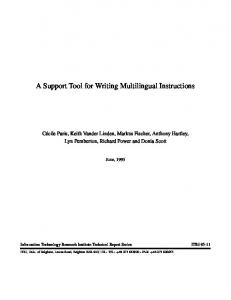
do not take advantage of the issues described in section 1.2.1 as inter module parallelism will be addressed in the second phase of the project. The Data Decomposition Tool generates a parallel module template based on the inputs supplied by the user: • Input data distribution schemes; • Neighbourhood and boundary data processing; • Parameters to the module; • Output data composition; • Parallel platform specific information. 3.1 Input data Distribution Schemes A number of distribution schemes are supported for a particular dataset over a number of processes. Distribution schemes in other systems were examined [3], [26], [27] and the following set is used to specify the distribution of each dimension in a dataset: Preserve: the dimension is not subdivided; Block: subdivide into equal blocks among the processes; Cyclic: subdivide using a cyclic distribution; Application: a user/application defined subdivision. A combination of these distribution schemes can be used to define common methods of distributing data for visualization tasks, see figure 3.
P1 P2
P3
P4 P5
P6
P7 P8
P9
1 2 3 4 5 6 7
(Block,Preserve,Preserve) (Block,Block,Preserve) Between 7 processors Between 9 processors
P1 P2 P3 P1 P2 P3 P1
(Preserve,Cyclic,Preserve) Between 3 processors
Application Defined Format
Figure 3: Combining different distributions
A Data Decomposition Tool for Writing Parallel Modules in Visualization Systems: Page 4
April 1996
Presented and Published as part of the Eurographics UK 1996 Conference, Imperial College, London. 3.2 Neighbourhood and boundary processing
4 Parallel Module Structure
For some applications groups of worker processes will require data stored in neighbouring portions of the dataset. If a data portion is on the boundary of the complete dataset then accesses outside the boundary needs handling.
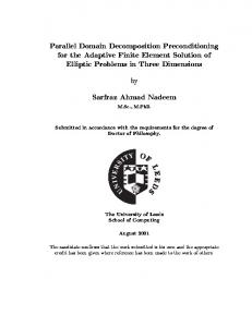
The structure for a parallel module [21] within AVS/Express has four main components shown in figure 4. The figure shows two types of Express objects:
The user specifies this extra information using the following: Neighbourhood: whether the region should be grown or shrunk and the extent in each dimension for this operation. Boundary: if an access goes outside the boundary the choice of actions are: no expansion, expand with a value, use nearest boundary value or assume the dataset is cyclic.
Pure: native Express field containing no extra information; Tagged: native Express field with extra information on the location of the data, distribution scheme and associated process for a particular data portion.
Parallel Module Interface DISTRIBUTER
3.3 Output data composition In the prototype version, when the processed data portions are collected from the workers they are composed into a single Express field. 3.4 Platform specific information When a module is generated it needs some extra information about the target platform it will execute on e.g., number of processes available, network location, special startup commands. The target platform is chosen initially when the module is generated from a list of possible selections. This information is static but in later stages of the project the user/system will be able to change the target platform or alter certain execution characteristics e.g., number of processes. 3.5 Module template output DDTool outputs a macro module which contains four main components described in more detail in section 4. One of these components, the worker, is where the user must provide the application code to process a portion of the dataset. The VPRvsi layer provides an interface similar to the one a sequential module uses to access the data objects. This ensures a user need not become familiar with a totally new set of library calls when writing a parallel module.
Param1 Param2 ParamN
HARNESS Setup WORKERS Update WORKERS
COMPOSITOR
WORKERS
Parallel Module Interface
Objects in Express Object Manager “pure” Express object “tagged” Express object Figure 4: Structure of a Parallel Module The four main components are: Distributer: handles the field input to a parallel module. This could either be a pure or tagged Express field; Compositor: handles the output from a parallel module. This could either be compositing the data into an Express field or sending the tagged field to another distributer; Harness: control process for the parallel module; Worker: processes a data portion.
A Data Decomposition Tool for Writing Parallel Modules in Visualization Systems: Page 5
April 1996
Presented and Published as part of the Eurographics UK 1996 Conference, Imperial College, London. Figure 5 shows a parallel module in AVS/Express. The module has three input parameters, one field and two float parameters. The module marked VPR_distributer creates tagged Express fields which are distributed to the worker processes by VPR_harness. Finally VPR_compositor generates a single Express field which is passed as output from the module
1. Starts up the workers; 2. Configure the workers to process neighbourhood data if necessary; 3. Inform the workers on changes within the module to objects (parameters) or whether the worker should exit. The harness has the option of starting up enough workers to process the complete set of tagged fields or to operate a task-farm style of operation. The workers do not need to know which style is being used as they simply process a data portion when notified by the harness. Task farming cannot be used if a worker’s computation relies on swapping updated neighbourhood data during iterations. A worker may be waiting for an update from its neighbouring portion which is still waiting to be processed. Other workers may also be dependent upon other portions and deadlock is a potential hazard. 4.4 Workers
Figure 5: A Parallel Module in AVS/Express 4.1 Distributer This uses VPRidd routines to calculate distribution of the Express field. The output is an array of tagged fields containing this information. Later versions of this component will take as input tagged fields and make decisions on whether to choose a new distribution pattern or pass on the data unchanged. 4.2 Compositor This removes the tagged information to produce a pure Express field. Later versions of this component will perform different composition strategies and make decisions on whether to composite the data into a pure Express field or pass the tagged fields on unchanged. 4.3 Harness The harness performs a number of tasks:
These components process the data portions and swap updated neighbourhood data if needed. The concepts and library interface used within the worker to access data should be similar to those of the code a user would produce when implementing a sequential module in AVS/Express. The workers perform a number of tasks: 1. Initialisation; 2. Configure themselves for neighbourhood processing if necessary; 3. Process events from harness; 4.4.1 Events from the harness There are two types of event the harness can send to a worker process: Parameter change: This notifies a worker to execute its update method; Exit: This informs a worker process to exit. The parameter change event from the harness is accompanied with a reference to the location of the parent object. This could be another process, shared memory segment or object identifier into the Distributed Object Manager (DOM). The workers update method is invoked passing the ref-
A Data Decomposition Tool for Writing Parallel Modules in Visualization Systems: Page 6
April 1996
Presented and Published as part of the Eurographics UK 1996 Conference, Imperial College, London. erence as the parent object identifier argument to the method. In the prototype version the reference to the data is the process identifier of the module’s harness. Therefore once the harness has informed the workers that a parameter has changed it executes code to distribute the data. The VPRvsi routines are built on top of the VPRdd and VPRidd routines to aid porting to other visualization systems. These support libraries are described below.
5 VPRidd and VPRdd Routines The VPRidd and VPRdd routines do not perform any intelligent partitioning or processing but rather provide the mechanism for an application or tool, such as DDTool, to define these groupings and have the actions carried out across different platforms. The main routines perform:
The second phase of the project will handle inter module parallelism addressing the issues related to implementing a parallel visualization system. The tools developed during this phase will manage the parallel modules providing facilities to control the placement and characteristics of the modules. An important part during this phase is providing useful performance feedback to aid the users decisions.
7 Acknowledgments The authors of the paper would first like to thank EPSRC for funding the project under the PSTPA initiative. They would also like to acknowledge Gary Oberbrunner, Advanced Visual Systems Inc., for the ideas and comments he has input to the project. We are also grateful for the support from our industrial collaborators AVS/UNIRAS Ltd. and Meiko Ltd. Finally thanks to our colleagues in the Computer Graphics Unit, Manchester Computing and LSI, University of Sa˜o P a˜ulo.
• Calculate data distribution schemes;
8 References
• Form neighbourhoods for processing;
[1] Upson C et al, “The Application Visualization System: A Computational Environment for Scientific Visualization”, IEEE Computer Graphics and Applications, 9(4), pp 30 -42, 1989. [2] “IRIS Explorer - Technical Report”, Silicon Graphics Computer Systems. [3] Lucas B, Abram G D, Collins N S, Epstein D A, Gresh D L, McAuliffe K P, “An Architecture for a Scientific Visualization System”, Proceedings of Visualization ‘92, IEEE Computer Society Press, 1992. [4] Rasure J, Young M, “An Open Environment for Image Processing Software Development”, SPIE/ IS&T Symposium on Electronic Imaging Proceedings, Vol. 1659, February 1992. [5] Message Passing Interface Forum, “MPI: A message-passing interface”, Computer Science Department Technical report No. CS-94-230, University of Tennessee, Knoxville, TN, April 1994 (Also in International Journal of Supercomputer Applications, Volume 8, Number 3/4, 1994). [6] Gropp W, Lusk E, Skjellum A, “Using MPI: Portable Parallel Programming with the MessagePassing Interface”, MIT Press, 0-262-57104-8, 1995. [7] “Pthreads: POSIX threads standard”, IEEE Standard 1003.1c-1995.
• Distribute data portions • Swap/update neighbourhood information. There are a number of utilities routines which are used by the main routines to pass portions of arrays between processes. Some of these routines also implement growing and shrinking neighbourhood regions and boundary processing. The prototype system is built upon MPI; it was decided to adopt MPI over other message passing libraries for the following reasons: • To ensure the code is future proof and portable; • The mechanisms provided for building safe parallel libraries in MPI; • Derived Data Types in MPI for extracting data directly from arrays; • Problems of packing/unpacking buffers for sending data;
6 Conclusions and future work The first phase of the project has been addressing the need to provide tools which aid the generation of parallel visualization modules.
A Data Decomposition Tool for Writing Parallel Modules in Visualization Systems: Page 7
April 1996
Presented and Published as part of the Eurographics UK 1996 Conference, Imperial College, London. [8] Whitman S, “Survey of Parallel Approaches to Scientific Visualization”, Computer Aided Design, Volume 26, Number 12, pages 928-935, December 1994 [9] Grant A J, “Parallel Visualization”, Presented at EASE Visualization Community Club seminar on Parallel Processing for Visualization, University of Manchester, November 1993. [10] Woys K, Roth M, “AVS Optimisation for Cray Y-MP Vector Processing”, Proceedings of AVS ‘95, pages 145-162, Boston MA, US, 1995. [11] Ford A, Grant A J, “Adaptive Volume Rendering on the Meiko Computing Surface”, Parallel Computing and Transputer Applications Conference, Barcelona, 1992 [12] Cheng G, Fox G C, Mills K, Marek Podgorny, “Developing Interactive PVM-based Parallel Programs on Distributed Computing Systems within AVS Framework”, Proceedings of AVS ‘93, pages 171-179, 1993. [13] Chen P C, “Climate Simulation Case Study III: Supercomputing and Data Visualization”, Proceedings of AVS ‘95, pages 373-384, Boston US, 1995. [14] Krogh M, Hansen C D, “Visualization on Massively Parallel Computers Using CM/AVS”, Proceedings of AVS ‘93, Orlando, USA, 1993. [15] Thornborrow C, Wilson A J S, Faigle C, “Developing Modular Application Builders to Exploit MIMD Parallel Resources”, Proceedings of Vis ‘93, pages 134-139, IEEE Computer Society Press, 1994. [16] Tsui K K, Fletcher P A, Hutchins M A, “PISTON: A Scalable Software Platform for Implementing Parallel Visualization Algorithms”, CGI ‘94, Melbourne, Australia, 1994. [17] Thornborrow C, “Utilising MIMD Parallelism in Modular Visualization Environments”, Proceedings of Eurographics UK ‘92, Edinburgh, March 1992. [18] Larkin S, Grant A J, Hewitt W T, “A Generic Structure for Parallel Modules in Visualization Systems”, In Preparation, 1996. [19] Larkin S, Grant A J, Hewitt W T, “Vipar Libraries to Support Distributed Processing of Visualization Data”, Proceedings of HPCN ‘96, Brussels, Belgium, April 1996. [20] Vroom J, “AVS/Express: A New Visual Programming Paradigm”, Proceedings of AVS 95, pages 65-94, Boston MA, 1995.
[21] Lord H, “AVS/Express Product Family Overview”, Proceedings of AVS 95, pages 3-13, Boston MA, 1995. [22] Oberbrunner G, “MP/Express Preliminary Specification”, Internal Technical Report, Advanced Visual Systems Inc. December 1994. [23] Chapple S, “Parallel Utilities Libraries-RD Users Guide”, Edinburgh Parallel Computing Centre (EPCC), UK, Technical Report, 1992. [24] “HPF: language definition document”, published in Scientific Programming, Vol. 2, no. 1-2, pp. 1-170, John Wiley and Sons.
A Data Decomposition Tool for Writing Parallel Modules in Visualization Systems: Page 8
April 1996