for parallel computation to address the coefficient matrix issue. The meshless method ... reveal the domain decomposition meshless methods produce accurate ...
Track-4 TOC Proceedings of HT-FED04 2004 ASME Heat Transfer/Fluids Engineering Summer Conference July 11-15, 2004, Charlotte, North Carolina USA
HT-FED04-56004 Proceedings of HT2004 2004 ASME HEAT TRANSFER/FLUIDS ENGINEERING SUMMER CONFERENCE Charlotte, North Carolina, USA July 11–15, 2004
HT-FED2004-56004
A PARALLEL DOMAIN DECOMPOSITION TECHNIQUE FOR MESHLESS METHODS APPLICATIONS TO LARGE-SCALE HEAT TRANSFER PROBLEMS Eduardo Divo** , Alain J. Kassab* , Eric Mitteff * , and Luis Quintana* ** Department of Engineering Technology * Department of Mechanical, Materials, and Aerospace Engineering University of Central Florida Orlando, Florida 32816-2450
Abstract
Nomenclature
Mesh reduction methods such as the boundary element methods, method of fundamental solutions or the so-called meshless methods all lead to fully populated matrices. This poses serious challenges for large-scale three-dimensional problems due to storage requirements and iterative solution of a large set of non-symmetric equations. Researchers have developed several approaches to address this issue including the class of fast-multipole techniques, use of wavelet transforms, and matrix decomposition. In this paper, we develop a domaindecomposition, or the artificial sub-sectioning technique, along with a region-by-region iteration algorithm particularly tailored for parallel computation to address the coefficient matrix issue. The meshless method we employ is based on expansions using radial basis functions (RBFs). An efficient physically-based procedure provides an effective initial guess of the temperatures along the sub-domain interfaces. The iteration process converges very efficiently, offers substantial savings in memory, and features superior computational efficiency. The meshless iterative domain decomposition technique is ideally suited for parallel computation. We discuss its implementation under MPI standards on a small Windows XP PC cluster. Numerical results reveal the domain decomposition meshless methods produce accurate temperature predictions while requiring a muchreduced effort in problem preparation in comparison to other traditional numerical methods.
X ÐBÑ `Î`8 ;ÐBÑ f# 5 3 ?ß @ RF RM α4 ;4 ÐBÑ and on the domain H and requiring the field variable to be globally expanded about these points as: R FR M 4œ"
where: R F À Boundary expansion points R M À Internal expansion points α4 À Expansion coefficients ;4 ÐBÑ À Expansion functions
Ð3Ñ Polyharmonic splines:
`X ÐBѺ 1# X ÐBѺ œ 1$ º `8 > > >
38 #H
;4 ÐBÑ œ
38 $H
Ð8ÑÓ Ò"Î>Ð8ÑÓ
ww
XHM " XHM # V ;HM " # # ww XHM " XHM # V ;HM # œ # #
s MH œ X " s MH X #
Ð29Ñ
R T VS
Ð26Ñ
8œ"
where >Ð8Ñ is the running time it took the 8>2 processor in the solution of the test problem. Using these definitions the following condition is satisfied:
ww
where V is the thermal contact resistance imposing a jump on the interface temperature values to account for a case where a physical interface exists. These now matched temperatures along the interfaces are used as the next set of boundary conditions. The iteration process is continued until a convergence criterion is satisfied. A measure of convergence may be defined as the P# norm of mismatched temperatures along all interfaces as: Í M Í # Í " R s M3 ‹ P# œ Ð27Ñ ŠX3M X M Ì R 3œ"
R T VS
J VEÐ8Ñ œ "
The faster the 8>2 processor, the larger J VEÐ8Ñ assigned to the 8>2 processorÞ The PSEHÐ8Ñ vector is a function measuring the load to the 8>2 processor in solving the actual problem and that is defined as: RV
PSEHÐ8Ñ œ 5œ"
where R M is the number of collocation points along all interfaces. This norm measures the standard deviation of the interface temperatures X3M and the averaged-out updated s M3 . The iteration routine can be stopped interface temperatures X once this standard deviation reaches a small fraction % of ?X7+B , where ?X7+B is the maximum temperature span of the global field. It is noted, that we refer to an iteration as the process by which an iterative sweep is carried out to update both the interfacial fluxes and temperatures such that the above norm may be computed.
The domain decomposition formulation detailed above is ideally suited to parallel computing. The algorithm has been coded and implemented in a 10-node 1.8-2.0GHz 1GB RDRAM PC cluster running Windows XP and MPICH [10-12] and compiled with the COMPAQ Visual FORTRAN. The parallel code collapses to serial computation if a single processor is assigned to the cluster. Upon launching the code under MPI, the processors are identified and given a rank. A small sample problem is solved on all processors to identify their relative performance. A load balancing routine is then performed to optimally assign domains to each processor by minimizing an objective function that contains information with regards to sub-domain sizes and relative computational capability. Specifically, the following objective function is minimized:
ÒMPSEHÓ œ
1 2 ã R T VS
R Ð5Ñ + “ R>9>+6
Ð31Ñ
1 0 0 1 0 0
2 1 0 0 0 0
3 0 1 0 0 0
â 0 0 0 0 1
0 1 0 0 0
0 1 0 0 0
0 0 0 1 0
RV 1 0 Ð32Ñ 0 0 0
This optimization is performed using a discrete Genetic Algorithm. A key step in the domain decomposition is to keep each sub-domain to a number of collocation points that allows the problem to be stored in available RAM avoiding disk paging.
R T VS
ÒPSEHÐ8Ñ J VEÐ8ÑÓ#
MPSEHÐ8ß 5Ñ ‚ ’
Here, there are 5 œ "ß #ÞÞÞR V regions or sub-domains in the actual problem to be solved, region 5 has R Ð5Ñ boundary and internal collocation points, and there are R>9>+6 number boundary and collocation points in the entire domain. The power + œ $ when a direct solver is used for each sub-domain problem and + œ # when GMRES is used to solve each sub-domain problem. The terms MPSEHÐ8ß 5Ñ come from a matrix ÒMPSEHÓ assigning loads of certain regions to certain processors. ÒMPSEHÓ is a Boolean matrix denoting the sub-domain assignment to the processorsÞ For example, the ÒMPSEHÓ matrix shown below shows a current configuration for an 8region ÐR V œ )Ñ and 5-processor ÐR T VS œ &Ñ problem . In the displayed load configuration, processor 1 is assigned regions 2 and 8, processor 2 is assigned regions 3, 5, 6 while the remaining processor are assigned each a region as:
Implementation on a Parallel Cluster
Wœ
Ð30Ñ
8œ"
Numerical Test of Coefficient Matrix Behavior
Ð28Ñ
A simple test case is undertaken to investigate the behavior of typical collocation matrix. The 2D polyharmonic RBF splines with 8 œ # are used to globally expand by direct collocation a " ‚ " square region. Ten (10) collocation points are used along each side of the boundary and one hundred (100) collocation
8œ"
where there are 8 œ "ß #ÞÞÞR T VS processors available in the cluster. The fraction of the overall inverse time it took the R >2 computer to solve the test problem is defined as: 6
6
Copyright © 2004 by ASME
points are uniformly distributed in the interior. Figure 5 shows the collocation point distribution along with the contour plots of a sample exact solution of the Laplace equation and its corresponding expansion. First kind boundary conditions were imposed everywhere except at the right-hand wall. The exact and meshless solutions appear to be virtually identical with a total RMS error of less than 0.3%. However, as shown below in Fig. 6, the contour plots of the B-derivatives of the same exact solution and meshless approximation reveal large deviation with a total RMS of over 12%.
However, both of these methods pose additional computations and do not address the issue raised by storage of the coefficient matrix. The domain decomposition approach effectively addresses both these issues.
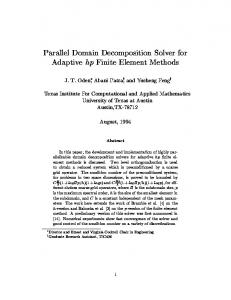
Figure 7. Contour and surface plot of the collocation matrix pattern for the sample square region. 102 101 100 Singular Value (SV)
Figure 5. Sample square region geometry and collocation point distribution with exact and meshless solutions.
10-1 10-2 10-3 10
-4
10-5 10
-6
10
-7
35
70 SV Vector Element Number
105
140
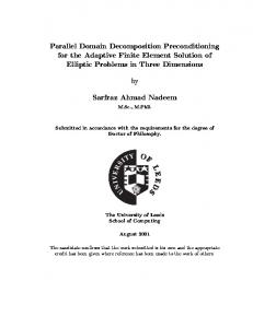
Figure 8. Sorted singular values of the collocation matrix for the sample square region. (Log-scale)
Figure 6. Contour plots of the exact and meshless approximation of the B-derivative for the test case.
Numerical Verification on a Regular Region An initial test is undertaken where a steady heat conduction problem is solved in a long rectangular solid region of length P œ "#Þ) and height 6 œ !Þ#. The boundaries are imposed with temperature X œ ! at the bottom and left walls while the top and right walls are imposed with heat flux ; œ ". The thermal conductivity is 5 œ "%Þ*. An analytical solution can be found through simple separation of variables as: ∞ X ÐBß CÑ œ I8 =382Ð$8 BÑ =38Ð$8 CÑ Ð33Ñ
The erratic behavior of the derivative can be attributed to the nearly singular nature of the collocation matrix. The matrix is built up using double-precision variables as well as for the Singular-Value decomposition (SVD) that followed. Figure 7 shows the pattern of the "%! ‚ "%! matrix from a plan view and in perspective. Notice the completely unbalanced behavior of the matrix showing large peaks at scattered positions and a large number of near-zero quantities. Figure 8 shows the plot of the sorted singular values for this matrix in logarithmic scale. Notice the sudden drop in the singular values from a maximum of )&Þ%$ to a minimum of #Þ($ † "!( for a conditioning number O œ $Þ"# † "!) . More than )!% of the singular values are below a "!' fraction of the maximum singular value. For this reason, special attention must be paid to the explicit calculation of the field variable derivatives. For the examples presented in this study a weighted combination of direct differentiation through the RBF expansion and smoothed finite difference approximations was employed. The behavior of the collocation matrix also reveals that preconditioning algorithms must be employed in order to carry out successful global expansions. Either a truncated singular value decomposition (TSVD) and an incomplete LU decomposition (ILU) may be easily implemented to pre-condition and solve the matrix systems that arise from global RBF expansions.
8œ !
∞
J8 =38Ð#8 BÑ =382Ð#8 CÑ
8œ !
where: I8 œ
6 $8#
# -9=2Ð$8 PÑ
Ð34Ñ
1 Ð#8 "Ñ #6 # J8 œ # P #8 -9=2Ð#8 6Ñ 1 #8 œ Ð#8 "Ñ #P $8 œ
7
7
Copyright © 2004 by ASME
A total of &#! Ð# ‚ #&' # ‚ %Ñ collocation points are used on the boundary and "!#% Ð#&' ‚ %Ñ collocation points in the interior for the 1-region expansion case as seen in Fig. 9 below. q = -1 T=0
(a) q = -1
T=0
(b) Figure 9. Geometry, boundary conditions, and zoom of the point collocation for the long rectangular slab.
(c)
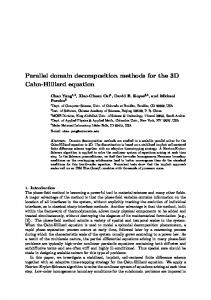
The long rectangular slab is decomposed into 2, 4, 8, 16, 32, and 64 sub-domains in the longitudinal direction with a total of 4 collocation points along each of the interfaces. A plot of the isotherms around the top-right corner of the slab is shown for the exact, 1-region, and multi-region cases in Fig. 10. The plots reveal that accurate solutions are obtained as agreement between the exact, single, and multi-region meshless solutions is excellent with a maximum relative error occurring consistently at the top-right corner in all cases. The relative error there is !Þ(&)% for the 1-region case and reaches up to "Þ$$&% for the 64-region case. The progression of the iteration residuals for the single- and multi-region cases is shown if Fig. 11 revealing the steep convergence behavior for all cases. A tolerance of "!% was employed for the iteration processes and met in just five (5) iteration for the 64-region case. The successive set of plots show the significant computational savings and improvements when the domain decomposition approach is followed. First the CPU time in seconds is shown in Fig. 12 on a logarithmic scale decreasing from around ")'!= for the 1-region case to less than %= for the 64-region case on a single CPU in the cluster. Figure 13 shows the decrease in hard-drive storage requirements from a total of 110MB to just over 4MB for the 64-region case distributed throughout the cluster nodes. Figure 14 shows a steeper reduction in simultaneous RAM allocation from 54MB to just 25kB for the 64-region case. The most significant improvement is illustrated in Fig. 15 where the dramatic reduction in collocation matrix conditioning number can be seen in a logarithmic scale. The conditioning number drops from #Þ)) † "!"% for the 1-region case to &Þ*& † "!( for the 64-region case, mitigating the certain near-singular behavior of the matrix to a high but reasonable conditioning number that allows for solution with controlled round-off error propagation.
(d)
(e) T:
0
0.002
0.004
0.006
0.008
0.01
0.012
0.014
0.016
0.018
0.02
0.022
Figure 10. Contour plots of the temperature for the: (a) Exact, (b) 1-region, (c) 4-region, (d) 16-region, and (e) 64-region cases. 0.07 0.06
1-region 2-region 4-region 8-region 16-region 32-region 64-region
Residual
0.05 0.04 0.03 0.02 0.01 0
1
2
3 Iteration
4
5
CPU time (s)
Figure 11. Residual evolution for single- and multi-region cases. 10
4
10
3
10
2
101
10
0
0
16
32 Number of Sub-Domains
48
64
Figure 12. CPU-time in seconds for single- and multi-region cases. (Log-scale)
8
8
Copyright © 2004 by ASME
points were collocated on the boundary and (!% points were uniformly collocated in the interior. The global expansion is tested for robustness by attempting to solve the same problem distributing the same number of internal collocation points nonuniformly, see Fig. 17. The geometry is also sub-divided into five (5) sub-domains to verify the domain decomposition approach. Twelve collocation points are distributed along each of the four interfaces as shown in Fig. 18.
120
Storage (MB)
100 80 60 40 20 0
0
16
32 Number of Sub-Domains
48
64 (0,9)
T=0
(3,9)
Figure 13. Total disk storage requirements in MB for single- and multi-region cases. (3,6) T = 0
q = -1 (9,6)
60000 T=0
RAM Requirement (kB)
50000
q = -1
40000 (3,3)
30000
(9,3) q = -1
T=0
20000 10000 0
(0,0)
16
32 Number of Sub-Domains
48
64
Figure 16. Geometry, boundary conditions, and uniform collocation point distribution for irregular region case.
Figure 14. RAM access requirements in kB for single- and multi-region cases. 10
(3,0) T=0
0
15
Conditioning Number
1014 10
13
10
12
10
11
1010 109 108 107
0
16
32 Number of Sub-Domains
48
64
Figure 15. Conditioning number decrease with domain decomposition from 1-region to 64-region case. (Log-scale) Figure 17. Non-uniform collocation point distribution.
The conditioning number may further be reduced in each subdomain by pre-conditioning via truncated SVD or ILU. Given the typical structure of the coefficient matrix and the distribution of eigenvalues, either method would be effective. However, it is expected that ILU would be the more computationally advantageous approach to follow. We leave this last point to further study.
Numerical Verification on an Irregular Region Next, the algorithm is tested in an irregular geometry to verify the convergence and accuracy of the domain decomposition approach. The geometry, boundary conditions, and collocation point distribution is shown in Fig. 16 below. The hole inside the domain is a " ‚ " square region. All surfaces are adiabatic except the ones specified. Again, the medium is stationary (solid) with a thermal conductivity 5 œ "%Þ* to provide a test for the pure conduction equation. A total of "'!
Figure 18. Domain decomposition and collocation point distribution for irregular region case.
9
9
Copyright © 2004 by ASME
The problem is solved using the single-region and multiregion collocation point distributions again significantly reducing storage, memory access, and computational time. The storage requirements were reduced from 34.1MB to only 12.7MB distributable in up to five (5) nodes in the cluster. The RAM simultaneous access was reduced from 17MB to 0.85MB. The CPU time was reduced from over 7 minutes to less than 1 minute. In addition, the conditioning number of the coefficient matrix was reduced from #Þ#" † "!"# to )Þ%# † "!* again demonstrating to be an effective pre-conditioning technique. Figure 19 shows the isotherm distribution for the 1-region case with uniformly distributed collocation points, the 1-region case with non-uniformly distributed collocation points, and the 5region case. The non-uniform distribution of collocation points produces a solution in close agreement with the one generated with the uniform distribution of collocation points with some deviations specially close to the boundaries of a maximum of less than "%. The 5-region domain decomposed implementation produces a solution virtually identical to the 1-region solution converging in "# iterations to a tolerance of "!% .
sub-domain interfaces. The iteration process converges rapidly, offers substantial savings in memory, and features superior computational efficiency. The meshless iterative domain decomposition technique is ideally suited for parallel computation. We discuss its implementation under MPI standards on a small Windows XP PC cluster. Numerical results reveal the domain decomposition meshless methods produce accurate temperature predictions while requiring a muchreduced effort in problem preparation in comparison to other traditional numerical methods. We also investigated through a numerical example, the nature of the resulting coefficient matrix and conclude that the conditioning number may further be reduced in each subdomain by pre-conditioning via truncated SVD or ILU. We leave this last point to further study where we will extend our approach to solution of the Navier-Stokes equations.
Numerical Verification of Advection-Diffusion Model in a Channel Finally, the full advection-diffusion model is tested in a "! ‚ "-7 channel with laminar fully-developed flow with a developing thermal field, solving the classical Graetz entry length problem. The fluid is air with density 3 œ "Þ##&51Î7$ , specific heat - œ "!!'Þ%$N Î51O , thermal conductivity 5 œ !Þ!#%#[ Î7O, and absolute viscosity . œ "Þ(* † "!& 51Î7=. The velocity profile is parabolic with a maximum velocity at the center line ?! œ !Þ#&7Î=. The flow is incoming with a bulk temperature X38 œ !°G while the channel walls are kept at a temperature XA+66 œ "!!°G . The outlet condition is considered adiabatic. A finite volume mesh consisting on 4825 nodes is setup to solve the problem using the commercial code Fluent 6.1 and compare it to the meshless solutions using 110 collocation points distributed around the boundary and 250 collocation points uniformly distributed in the interior as seen in Fig. 20. The problem is solved using a singleregion and a 10-region meshless collocation approach. The contour plot shown in Fig. 21 reveals excellent agreement between the 1-region and 10-region meshless solutions and the CFD solution provided by Fluent. Figure 22 shows a comparison between the CFD and the meshless temperature profiles after 1/4, 1/2, 3/4, and the full length of the channel again revealing excellent agreement.
(a)
(b)
Conclusions We developed a domain-decomposition along with a regionby-region iteration algorithm particularly tailored for parallel computation to address the numerical issues arising due to the nature of the coefficient matrix in radial basis function based meshless methods. An efficient physically-based procedure provides an effective initial guess of the temperatures along the
(c)
T:
0
0.01 0.02 0.03 0.04 0.05 0.06 0.07 0.08 0.09 0.1 0.11 0.12 0.13
10
10
Copyright © 2004 by ASME
Figure 19. Isotherm plots for the irregular region case: (a) 1region uniform, (c) 1-region non-uniform, and (b) 5-region.
References [1] Belytscho, T., Lu, Y.Y., and Gu, L., "Element-free Galerkin methods," Int. J. Num. Methods, Vol. 37, 1994, pp. 229-256. [2] Atluri, S.N. and Zhu, T., "A new meshless local PetrovGalerkin (MLPG) approach in computational mechanics," Computational Mechanics, Vol. 22, 1998, pp. 117-127. [3] Melenk, J.M. and Babuska, I., "The partition of unity finite element method: basic theory and application," Comp. Meth. Appl. Mechanics and Eng., Vol. 139, 1996, pp. 289316. [4] Kansa, E.J., "Multiquadrics- a scattered data approximation scheme with applications to computational fluid dynamics I," Comp. Math. Appl., Vol. 19, 1990, pp. 127-145. [5] Franke, R., "Scattered data interpolation: Test of some methods," Math Comput., Vol. 38, 1982, pp. 181-200. [6] Cheng, A.H.-D., Golberg, M.A., Kansa, E.J., Zammito, G., "Exponential Convergence and H-c Multiquadric Collocation Method for Partial Differential Equations," Numerical Methods in P.D.E., DOI 10.1002/num. 10062, 2003. [7] Gottlieb, D. and Orzag, S.A., Numerical Analysis of Spectral Methods: therory and applications, Society for Industrial and Applied Mathematics, Bristol, England, 1977. [8] Powell, M.J.D., "The Theory of Radial Basis Function Approximation," in Advances in Numerical Analysis, Vol. II, Light, W., ed., Oxford Science Publications, Oxford, 1992. pp. 143-167. [9] Divo, E., Kassab, A.J., and Rodriguez, F., "A Parallelized Iterative Domain Decomposition Approach for 3D Boundary Elements in Non-Linear Heat Conduction," Numerical Heat Transfer, Numerical Heat Transfer, Part B: Fundamentals. Vol. 44, No. 5. pp. 417-437. [10] Gropp, W., Lusk, E. and Thakur, R., Using MPI: Portable Parallel Programming with the Message-Passing Interface, The MIT Press, Cambridge, MA, 1999. [11] Gropp, W., Lusk, E. and Thakur, R., Using MPI-2: Advanced Features of the Message-Passing Interface, The MIT Press, Cambridge, MA, 1999. [12] Sterling, T.E., Beowulf Cluster Computing with Windows, MIT Press, Cambridge, 2001.
Figure 20. Channel geometry, CFD mesh, and collocation point distribution for the 1-region and 10-region heat advectiondiffusion problem.
T:
0
10
20
30
40
50
60
70
80
90
100
Figure 21. Temperature contour plots of the CFD solution, 1region, and 10-region solutions of the heat advection-diffusion problem in a channel.
0.01 0.009 0.008 0.007
1/4 1/4 1/2 1/2 3/4 3/4 1/1 1/1
y
0.006 0.005 0.004 0.003
CFD Meshless CFD Meshless CFD Meshless CFD Meshless
0.002 0.001 0 270
280
290
300
310
320
T
330
340
350
360
370
Figure 22. Temperature profile comparisons between the CFD and the 1-region meshless solutions at: 1/4 length, 1/2 length, 3/4 length, and outlet of the channel. 11
11
Copyright © 2004 by ASME