A DC Controllerr for Continuous Variable Series R Reactors (CVSRs) Sheng Zheng, Jingxin Wang,, Fei Yang, Fred Wang, Leon M. Tolbert and Daniel J. Costinett Center for Ultra-wide-areea Resilient Electric Energy Transmission Networks (CUR RENT) Department nt of Electrical Engineering and Computer Science The University of Tennessee Knoxville, TN 37996-2250, USA
[email protected] Abstract—Continuous variable series reactoors (CVSRs), as a cost effective alternative to flexible AC tran nsmission system (FACTS) series compensators, have been proposed to continuously vary the line reactance and controol the power flow. The development of the power electronics baased dc controller (DCC) is essential and unique to meet the need oof CVSR in utility transmission grid applications. In addition tto supplying the needed dc current to the CVSR dc winding, thee DCC has to deal with the interaction from the ac winding. CVS SR, together with DCC, will be installed outdoor in a substation,, so the operation environment could be extremely harsh. The deetailed design and implementation of the DCC are presentted, along with simulations demonstrating the close relationsship between the load profile of dc winding and converter outp put impedance. A 1000 A, 20 kW field prototype has been constrructed and tested with a 115 kV, 1500 A CVSR to experimeentally verify the performance of the whole CVSR system.
n of the simple CVSR in The asymmetrical configuration Fig. 1(a) will introduce harmonics into the controlled ac w add in one half cycle of system, since the ac and dc fluxes will one ac period and subtract in the other half cycle [9-11]. Another issue is the large magnitudee of back-emf to be induced on the dc winding, because of the acc flux swing. The improved CVSR shown in Fig. 1(b) significan ntly reduces harmonics and back-emf but cannot completely eliminate all these issues [4onverter is being designed, 5]. As a consequence, when the co these two impacts cannot be ignorred, especially the induced back-emf.
Keywords—Continuous variable series reeactors (CVSRs); magnetic characteristic; power flow; insulated gate bipolar transistor (IGBT); thermal model; flexible AC traansmission system (FACTS); DC current controller (DCC).
I.
(a)
INTRODUCTION
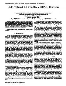
Series compensation using series capacitorrs or reactors can be an effective method for power flow control in ac grids [1-3]. Power electronics based series compensationn, as part of the flexible AC transmission system (FACTS) family, provides added functionality by enabling continuous controllability of the capacitance and inductance. As a cost efffective alternative to FACTS series compensators, a series rreactor has been proposed to continuously vary the line reacttance and control the power flow [4-5, 8]. The functional schematic of a basic conntinuous variable series reactor (CVSR) is depicted in Fig. 1(a)), in which an ac winding and a dc winding are wound respecttively on the two legs of one magnetic core. The ac winding is the controlled element which can be connected into an ac ttransmission line system. The dc current regulator is the controolling element for CVSR through a dc winding, which can vary th the dc bias flux as well as the magnetization level of the satuurable-core. As a result, the ac reactance reaches the maximum when the bias dc flux equals to zero and the minimum when the core is fully saturated [4-8].
978-1-4673-7151-3/15/$31.00 ©2015 IEEE
(b) Fig. 1. (a). Functional schematic of a basic CVSR (b). Schematic of an improved CVSR
This paper presents the dev velopment of the power electronics based dc controller (DCC C) for CVSR. In addition to supplying the needed dc current to the CVSR dc winding, the n from the ac winding, such DCC has to deal with the interaction as the back-emf issue as mention ned above. Given that the CVSR will be installed outdoor in a substation for transmission line power flow control, reasonable manufacturing process and cost, reliable operation and low maaintenance for the DCC are all essential.
5786
TABLE I. Electrical Cooling System Control Environmental Input Dc Winding Load Reliability
DCC SPECIFICATIONS
Output dc current 0 to 1000 A; Output average dc voltage 0 to 60 V and also need to withstand induced ac back-emf (a function of saturation). Natural convection cooling to help the enclosure design and eliminate maintenance issues. Receives systematic commands (start/stop signal and required ac reactance) and measured ac winding reactance; Regulates ac winding equivalent reactance; Reports DCC and dc winding status back to the upper controller. Outdoor and weatherproof required; Ambient temperature variation: -40 to 50 °C. Ac input voltage: 3 Phase 480V; Voltage for control power: 125 V from substation battery Winding resistance 50 mȍ at 20 °C and 62 mȍ at 80 °C based on the thermal estimation on rated operating condition of CVSR; Equivalent inductance 1.2 mH to 2.2 mH as function of ac load and dc saturation. Tolerant to surge and other over voltages conditions from ac and dc sides; Self-protect during abnormal and fault conditions; high availability, reasonable manufaturing process and cost, low maintenance, and requires minimum human intervention. System Control Room
Buck Converter (DC Current Regulator) L
AC Breakers
Precharge Contactor
Hardwired Input & Output
R
1
Arresters
Commuication Unit
Systematic Communication (Modbus)
DCC Central Controller
Rshunt
480V
480V:208V D/Y
Io
C
Neutral
2 Main Contactor
125Vdc
Rshunt
Auxiliary Power Supply
Uo
Crowbar Bypass Switch
DC Windings
Single devices or parallelled devices
Fig. 2. Schematic of the dc current controller.
The DCC also acts as the interface of the whole CVSR system to the power system control, receiving commands and systematic information from the upper system-level controller, and providing necessary status updates and feedback to the system-level controller. The DCC is a unique power converter with special hardware and software requirements to meet the need of CVSR in utility transmission grid applications.
the source voltage, in addition of the dc link voltage, is obviously not sufficient to counteract such a high-amplitude back-emf.
In this paper, a succinct technical specification of DCC for CVSR will be presented first. Then the detailed design and implementation of the DCC hardware and software will be described in section III. Simulation and experimental results are presented next. The conclusion and future work are also provided. II.
CONVERTER SPECIFICATION
Fig. 3 shows the reactor portion of a demonstration unit of CVSR. It is rated nominally at 115 kV, 1500 A with a variable reactance between 2 and 5 Ω. To achieve such a variable reactance, a regulated dc current from 0 to 1000 A must be supplied by the DCC under different ac load and dc flux bias conditions. In addition, the DCC must meet other performance requirements and environmental conditions to guarantee its reliable operation in an outdoor substation. Table 1 lists the main specifications for the DCC as well as the input conditions and dc winding load parameters. Note that the induced ac back-emf voltage on dc winding generally consists of even order harmonics and can reach a magnitude on the order of kilo-volts. Under this circumstance,
Fig. 3. A demonstration unit of CVSR in a factory testing.
For the DCC design, it is necessary to develop an appropriate control algorithm to minimize the influence of back-emf on normal operation, both from the control and thermal point of view. Also, because a natural convection cooling system instead of forced air cooling is required to minimize maintenance, the design of DCC must carefully select the converter topology, which poses enormous impacts
5787
on passive component loss (e.g., dc link capacitors, inductors, etc.) and total loss and thermal performance of power semiconductor devices. Furthermore, high reliability is absolutely critical for acceptance in utility applications. The comparison of various topologies and the detailed design will be described in the following section. III.
TOPOLOGY SELECTION AND THE DCC DESIGN
A. Topology Selection The basic function of DCC is to convert three-phase ac voltage to a regulated dc current. Several topologies are capable of being selected as a candidate for the DCC to meet the specifications shown in Table. I. One-stage three-phase acdc buck rectifier (e.g. thyristor phase-controlled rectifier) is first considered, due to its simplicity and reliable performance. But this one-stage rectifier has two obvious drawbacks: not being able to provide bidirectional current (required as will be explained below) and also high losses.
Uo
Uo Back-emf
(a)
Back-emf
(b)
Io
When dc winding current needs to be decreased rapidly or the induced back-emf is low enough to be countered by a proper control algorithm, the full bridge converter is preferred due to its fast dynamic response and having both positive and negative voltage generating capability, because it can operate in reverse charging mode shown in Fig. 4 (b). Noted that Fig. 4 (c) and (d) are the two symmetrical freewheeling modes that effectively double the equivalent switching frequency and then decrease the switching loss of individual IGBT modules. In addition, by adding these two freewheeling modes into the converter modulation scheme, the current ripple flowing through the dc link capacitors can also be reduced significantly, leading to a smaller power loss on dc link capacitor bank. Paying attention to the differences between full bridge based converter and buck based converter, it is found that all these advantages mentioned before are at the expense of power device count. The output current of the DCC is so high that the conduction losses of power devices dominate comparing to the switching losses. In all operating modes shown in Fig. 4, there are two power devices conducting simultaneously, which further increases the conduction losses significantly. So the drawbacks of additional power devices are summarized below:
Io
Io
the desired current and additionally synthesize an ac component to counteract the back-emf. The dc component of output voltage is determined by the inductance and resistance of dc winding and the ac component is mainly related to the amplitude of the induced back-emf.
• Increased total power device losses, which places additional stress on the converter cooling system and enclosure design
Io Uo
Uo Back-emf
(c)
Back-emf
• Inability to prevent power flow back to dc link in the case of control loss. Since buck based converter is able to isolate the dc winding from dc link voltage by providing an automatic freewheeling path
(d)
Fig. 4. Four operating modes of full bridge based topology (a). Charging mode (b). Reverse charging mode (c). Freewheeling mode through upper devices (d). Freewheeling mode through lower devices.
• More auxiliary circuitry for IGBTs, including IGBT drivers, auxiliary power supplies and protection circuits • Much higher cost
Io
Io
Uo
Uo Back-emf
Back-emf
Fig. 5. Two operating modes of buck based topology (a). Charging mode (b). Freewheeling mode.
Two-stage topologies equipped with various types of dc-dc converter are alternative solutions, if a diode front-end rectifier is adopted. Fig. 4 and Fig. 5 demonstrate various operating modes of a full bridge based converter and buck based converter respectively. Both converters are capable of regulating dc current theoretically, shown in Fig. 4 and Fig. 5. In order to ideally output a dc current in this particular application, the DCC should generate a dc voltage to regulate
In addition, the amplitude of the induced back-emf is much greater than dc-link voltage in most cases when CVSR system is running. Because of this, any step-down converter topology cannot fully counter the back-emf. Therefore, the buck solution is preferred for DCC operation with proper control. The adopted control algorithm is not aiming at countering the backemf but preventing dc link voltage from being influenced by the back-emf. The only shortcoming is the slower dynamic response when dc current needs to be decreased. B. System Configuration The circuit configuration in Fig. 2 with a diode front-end rectifier and buck dc-dc converter using IGBT modules is selected for the DCC as explained before. The selected buck converter implementation is favored mainly because of its optimized loss/temperature profile of the power semiconductor devices and the self-isolated/self-protected mechanism in the case of control loss or relatively high ac back-emf. In addition,
5788
the negative current capability of DCC is required. Turning on the bottom IGBT is a possible solution, in that case, the negative current will not flow through anti-paralleled diode to charge dc link capacitors, which may lead to an overvoltage fault.
regulator. Fig. 7 shows the conceptual equivalent circuit of the CVSR dc winding and the DCC. Fig. 8 gives the control diagram of the buck based converter, where the feedback coefficient F is set to 1.
idc
The paralleled IGBT modules, the pre-charge and main contactors, the SCR bypass switch and crowbar, and the arresters are for operation modes control and transitions, protections, and reliability. Some details will be given in the section of thermal and reliability considerations. Enables PWMs
Control power lost
OFF
Disables PWMs
Sensor & communication self-detection
“Shutdown” from system
Faults occured
Ready to start
“Reset” from system level
Fault “Reset” command from system level
“Start” command from system level
Opens main contactor & precharge contactor
Closes main contactor & precharge contactor
Off Ready to start Ready to run Run Fault
DCC OPERATION MODES AND COMPONENT STATUS
Main contactor Off
Precharge contactor Off
Open
Open
Closed
Closed
Closed
Closed
Open
Open
Buck converter Off Off or diode freewheel Off or diode freewheel On Off or diode freewheel
Auxi. power Off
Bypass Switch Off
On
Open
On
Open
On
Open
On
Closed
C. Operation Modes For the required performance and reliability, the DCC is designed with five operation modes as listed in Table II. Their relationships and transitions are illustrated in Fig. 6. Note that faults here only refer to those that require DCC shutdown. The diode freewheeling is necessary when the dc winding current is stopped (during normal shutdown, stopping, or fault). The mode transition is managed by the DCC DSP, which communicates with the system-level controller such that system will have visibility of the DCC status. The “Off” status can be detected by the system-level controller via handshaking with DCC DSP. IV.
Vo
VBackemf
+ -
The dc winding can be represented by its equivalent resistance R, inductance L, and ac induced back-emf Vemf. Both L and Vemf are functions of ac winding current and magnetic core saturation characteristic. For the demo CVSR in Fig. 3, R is 50 m at room temperature (20 °C) and 62 m at 80 °C, L ranges from 1.2 mH to 2.2 mH, and Vemf can reach several kilovolts. As a current controlled converter, the DCC can be modeled by its Norton equivalent circuit. It can be seen that in order to achieve the “perfect” current regulation, the DCC must dynamically overcome Vemf, and then provide the necessary additional voltage for R and L to obtain the desired dc current. Given that the Vemf mainly consists of even order harmonics with a minimum frequency of 120 Hz, this “perfect” current regulation scenario would require the DCC output voltage to generate an ac voltage in kilo-volts range with high bandwidth, which would lead to high dc link voltage and high switching frequency, and ultimately high DCC losses.
Fig. 6. The relationships and transitions of different states. TABLE II.
Zdcc
Fig. 7. The conceptual equivalent circuit of CVSR dc winding and DCC.
“Stop” from system level Control & contactors power on
Gcidcref
Ready To run
L
+
“Run” from system level
Run
R
CONTROL DESIGN CONSIDERATION AND SIMULATION
A. Control Design Consideration The basic purpose of power electronics based converter is to satisfy the current requirement of CVSR dc winding, so dc current is regulated through the converter current control with a PI regulator. In addition, a tremendous ac back-emf will have a significant impact on the design and performance of the PI
Fig. 8. The control diagram of the buck based converter.
The approach adopted in this paper is to make DCC exhibit a very low impedance (that is, close to an ideal voltage source) at the ac voltage frequencies (120 Hz and higher), while keeping a good current regulation (i.e., close to an ideal current source) near dc. With a PI current regulator, the equivalent impedance Zdcc of the buck converter can be expressed as in (1), where Kp and Ki are the proportional and integral gains of the PI current regulators. Assuming a first-order behavior for the PI regulator, Kp and Ki should satisfy the relationship of Kp/L = Ki/R = Ȧc/Vdc = K, where Ȧc is the PI regulator bandwidth and K is a coefficient that needs to be determined in the control design consideration. ܼௗ ൌ െ
ܮȉ ݏଶ ൫ܴ ܸௗ ȉ ܭ ൯ ȉ ݏ ܸௗ ȉ ܭ ሺ ݏȉ ܮ ܴሻ ݏ (1)
Fig. 9 plots frequency response of the inverter output impedance Zdcc for varing values of K and the dc link voltage
5789
disadvantage of utilizing high bandwidth is increased dc link voltage ripple, which may easily lead to an unexpected activation of under-voltage or over-voltage protection circuits. This simulation example verifies the effectiveness of the control algorithm on the application of CVSR. Io / A
1800
120 Hz
K = 0.1
K = 0.2 DC Current
1000
Vb / A
200 1000
Back EMF
0 -1000 0.6
D
Vdc. Clearly, it is necessary to have low Ȧc to obtain low Zdcc at 120 Hz and beyond. The magnitude of Zdcc is low enough at 120 Hz when Ȧc is several tens of rad/s. As a result, we selected Ȧc to be 30 rad/s (4.78 Hz). Note that the impact of Vdc is negligible. With the selected Ȧc and Vdc, Zdcc equals to 0.06 at 120 Hz, so the converter output will see only 4.0% of Vemf with the worst case R and L values. For a Vemf on the order of several kilo-volts, the voltage drop on the DCC will be on the order of tens of volts. The dc link voltage is selected as 300 V to provide sufficient margin. However, it potentially can be even lower, trading off loss with dc link voltage ripple considerations.
Duty Cycle
0.3
Vdc / V
0 Magnitude (dB): 35.8 Magnitude (dB): 15.6
300
DC Link Voltage
260 220 0.96
Magnitude (dB): -4.48
1.06
1.00
t/s
Magnitude (dB): -24.4
Fig. 10. A simualtion with considering an estimated back-emf.
V. THERMAL AND RELIABILITY CONSIDERAIONS Load Current DC Bus Voltage
Fig. 9. Frequency response of the inverter output impedance Zdcc for varing values of K and the dc link voltage Vdc
Rated Current
One of the consequences to having low Ȧc and low Zdcc value at 120 Hz will be high ac ripple current in DCC. The ripple will not impact the CVSR to achieve the desired reactance over a full line period. However, its impact on CVSR winding loss and DCC loss (both switching and conduction loss) has to be considered. B. Simulation Verification Comprehensive simulation has been conducted to help design and verify the DCC control approach described above based on the equivalent circuit model in Fig. 7. The resistance of dc winding is related to its operating temperature and the inductance model and the amplitude of induced back-emf are determined by the non-linearity of the magnetic material. For simplicity, several constant Vemf with several constant R and L parameter combinations are assumed. Fig. 10 shows one example of the simulation results, whose detailed parameters are listed in Table. III. The amplitude of back-emf is set at 1000V as shown in Fig. 10. In Fig. 10, at time t = 1s, the control bandwidth is increased from 4.78 Hz to 9.56 Hz. The reduction in dc current ripple is minimal. However, the duty cycle of buck based converter has saturated and reached zero cycle by cycle, indicating the converter is out of control at this moment. Another
Device Parameters
Rated Voltage Physical Dimension
Heatsink
Junction Temperatures on IGBT and Diode
Modulation Scheme
Losses on IGBT and Diode
Topology Selection
Heatsink Temperature
It should be pointed out in the actual CVSR, the winding parameters L and R are variable and also difficult to model accurately, which makes the PI regulator design challenging. By using a slow regulator, such design difficulty can be relieved, though the true bandwidth may be quite different from the defined Ȧc.
Losses Profile
Switching Frequency
Total Losses
Electrical Loading
Thermal Behaviors
Module Config.
Fig. 11. Two groups of design parameters/freedoms contribute to the power losses and thermal behaviors of semiconductor modules.
To enhance the DCC reliability and reduce its maintenance requirements, considerations are given in four areas. A. Eliminate forced air cooling To ensure a reliable converter design and a safe operation temperature of power semiconductor modules, a cooling system is required. In general, a simple heatsink-fan cooling system can achieve maximum cooling at minimum weight [12]. However, since DCC requires minimized maintenance, the cooling system using fan or other moving parts poses a liability. The DCC design with only natural cooling will eliminate this issue but adds severe constraints on the converter design, especially for power loss and thermal behaviors of both passive components and power devices. It is critical to reduce the total converter loss and also the thermal resistance such that the cooling requirement will be satisfied.
5790
B. Reduced power losses and improve thermal behaviors of power modules Power losses and thermal behaviors of semiconductor modules are mainly determined by two design freedoms [13]: the electrical loading of converter (e.g. load current, dc bus voltage, switching frequency, modulation scheme, etc.) and device parameters (e.g. rated voltage, rated current, module physical dimension, module configuration, manufacturing process etc.). The contribution of these two groups of factors is summarized below, shown in Fig. 11. On-state Voltage (V)
Single Configuration Dual Configuration
2.5 FZ1200R12KF4
Fig. 12 and Fig. 13 list subset of 1200 V commercial power devices currently available in the market. The module configuration (number of devices in a module) has very little influence on the on-state voltage, as well as the junction to case thermal resistance. Thus, the dual configuration of power device is preferred, due to its easy installment and bus-bar design simplification for a buck based converter. There is also a trend that the higher rated current, the lower on-state voltage of power module will be, including both IGBT and antiparalleled diode. Additonally, the junction to case thermal resistance also becomes smaller when the rated current increases. Based on these factors, the detailed losses of all modules are evaluated and compared according to the known electrical profile. Without considering the influence of induced backemf, the duty cycle region of DCC is calculated by the given dc link voltage, rated load current and DC winding resistance:
2.0 FZ1200R12KL4C FZ1600R12KL4C
1.5
adopted control algorithm, it is possible to achieve the necessary reactance only utilizing a relative low dc link voltage and switching frequency.
CM1400DUC-24NF FZ1200R12HE4 CM1400DUC-24SFZ1600R12HP4 FZ1800R12HP4
݀ௗ ൌ
CM2500DY-24S
1.0 500
1000
1500
2000
2500
Rated Current (A)
TABLE III.
Fig. 12. On-state voltage of IGBT transistor chips comparison between the most popular commerical IGBT modules (Irated > 1000 A, Vrated = 1200 V). Junction to Case IGBT Thermal Resistance (K/kW)
Single Configuration Dual Configuration
25
ோȉூ
DCC ELECTRICAL PARAMETERS SHOWN IN FIG. 2
Rated load current, Io
Junction to Case Diode Thermal Resistance (K/kW)
1000 A
Maximum dc winding inductance
2 mH
Maximum dc winding resistance
0.062
Nominal DC link voltage, Vdc
35
(2)
280 V
Switching frequency, fsw
1200 Hz
Maximum duty cycle, dd
0.221
Assumed operating temperature, Top
75 °C
FZ1200R12HE4
30
20
IGBT module CM2500DY-24S
FZ1200R12KL4C
1200 V/2500 A
FZ1200R12KF4 FZ1600R12HP4
15
CM1400DUC-24S FZ1800R12HP4 CM1400DUC-24NF FZ1600R12KL4C
25 CM2500DY-24S
20
10 500
1000
1500
2000
2500
Rated Current (A)
Fig. 13. Thermal resistance (junction to case) of both IGBT transistor chips and diode chips comparison between the most popular commerical IGBT modules (Irated > 1000 A, Vrated = 1200 V).
According to the specification given in Table I, the maximum load current is 1000 A. Topology selection and modulation scheme have also been explained in the previous section. Beyond that, the dc bus voltage and the switching frequency need to be chosen to minimize the power losses. Generally speaking, decreasing switching frequency and lowering dc bus voltage are both effective ways to achieve the design goal. But as mentioned before, the DCC interfaces with dc winding of CVSR. In order to regulate the DCC output as a DC current source, high dc link voltage and switching frequency are essential. In this case, the switching loss of power device increases linearly with these two factors, which increases the requirement of cooling system. Thanks to the
Due to the special application of CVSR, the conduction period of diode chips is much longer than that of IGBT transistor chips, the temperature rise from junction to case could be much greater than other applications. The selection of greater current rating power device brings the benefits from both complete loss and thermal performance perspective, which ease the already-stringent requirements on heatsink design. In light of this analysis, to reduce the dominant conduction loss, the 1200 V, 2500 A IGBT module is selected for its low on-resistance and low thermal resistance. Paralleling another IGBT module, even in the event of non-equal current sharing helps to further reduce the conduction loss, distribute thermal load, and also provides redundancy. C. Components stress control and redundancy The analysis of complete loss and thermal performance of power modules explained the necessity and effectiveness of utilizing and paralleling the oversized switching devices (both current and voltage ratings). They are selected for reduced electrical and thermal stress and redundancy. Multiple 1000 V film capacitors each with 970 uF are used to share the
5791
estimated 420 A ripple current at the selected switching frequency. D. Protection In addition to protection functions normaally available in a power electronics converter (e.g., overcurreent, over-/undervoltage, over-temperature), the DCC provvides protection functions unique to CVSR. In particular, DC CC needs to deal with induced ac back-emf. The solution is a SCR based bypass with overvoltage switch/crowbar, which can be turned on w (crowbar function), or with a gate signal (bypass switch function). The bypass switch is useful especiallly in the event of IGBT module failures as it provides another ffreewheeling path for dc winding current. Arresters are also insttalled to suppress the initial overvoltage transient while waitingg for the SCR to turn on in several microseconds. It should bbe noted that all critical protections are implemented in hardw ware, independent of or in addition to software protections. Device junction temperatures are also monitored to allow over-temperature protection or proper de-rating adjustment. Thee status and fault types are reported to the system-level controller so the system can make decisions on reset, shutdown or de-raating. VI.
EXPERIMENTAL RESULT TS AC winding 106
1500 A CVSR
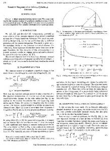
Fig. 14 shows the factory test settup for CVSR, where the ac winding current of a single phase CV VSR was directly energized by a high voltage, high power ac grid g source. The ac current could be adjusted from 0 – 1500 A rms, and the prototype DCC in Fig. 15 provided the adjustaable dc current (0 – 1000 A) to vary the CVSR reactance. The CVSR reactance curves as function of dc current for various ac currents are given in Fig. 16. It can be seen that the t 2 has been achieved at required ac reactance range of 5 to four different single-phase ac loadss, which are 250 A, 500 A, 750 A and 1000 A. However, for 1500 1 A ac current, it is still unsaturated even when the dc curreent is as large as 540 A. To achieve a 2.5 ac reactance at these five different ac current, the required dc currents are 120 A,, 180 A, 250 A, 330 A and 480 A respectively. The trend allso illustrates the growing requirement of dc current to partiallly or fully saturate the core when the ac current increases. It caan be explained that the ac flux variation induced by a lower ac current is much smaller than that of higher current. Only a small amount of dc current o the total flux into the can push the operation region of saturation area of magnetic core. An nother design consideration is the targeted ac reactance. After th hese curves reach 2 , even increasing several hundred ampeere dc current, their ac reactance only changes no more thaan 0.3 since the core has been fully saturated. Consequently, the targeted ac reactance should be decided by the knee point of the curves.
DC win nding
146.4
1000 A DCC
96
Unit: In nches Fig. 14. The setup configuration of factory test. Fig. 16. Measured CVSR reactance verse. dcc current at different ac loads.
Fig. 15. The prototype DCC providing adjustable dc currrent (0 – 1000 A) for the proposed CVSR.
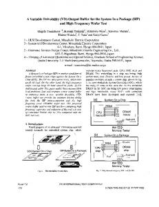
Fig. 17 shows the DCC outpu ut terminal waveforms for three different dc current scenarios when w the ac currents are all set at 500 A. Because of the small reesistance of dc winding and the low dc winding current, the duty y cycle of buck converter is relatively small in these cases (< 0.1), such that only short voltage pulses can be seen at the DCC output terminal. The a widely varying in these instantaneous dc winding currents are three scenarios, because of their varying operating saturation conditions. Fig. 17 (a) demonstratees an unsaturated condition of the magnetic core when the dc current reference is pretty CC performance when the low. Fig. 17 (b) illustrates the DC maximum amplitude of induced baack-emf is reached. Thanks to the proposed low control bandw width, the dc link voltage maintains at a constant value even when w the dc winding current ripple is relatively large. The dc component of the dc winding current is 200 A, with a peak-to-peeak current ripple of about 230 A at 120 Hz, which shows the significant impact of the
5792
induced ac back-emf as expected from the control described in the previous section. When the magnetic core is fully saturated, the induced back-emf is so small that its influence on dc winding current becomes negligible, which is shown in Fig.17 (c). DC Output Current: 20 A/div DC Link Voltage: 250 V/div DC Output Voltage: 250 V/div
prototype has been built and achieved the basic functionality of regulating dc current from 0 – 1000 A under different ac load and dc flux bias conditions. The system design process, including system configuration, operation modes, reliability considerations and control, makes DCC tolerant to surge and other over voltages conditions from both ac and dc sides. The DCC integrates self-protection functionalities. The low maintenance and minimum human intervention of DCC also meets the need for CVSR application in the power grid. The full scale factory test shows that the DCC can help to achieve approximately a 65% reduction of ac winding reactance, which verifies the effectiveness of the CVSR. ACKNOWLEDGMENT This work was supported primarily by the Advanced Research Projects Agency-Energy through Oak Ridge National Laboratory. This project made use of the Engineering Research Center Program of the National Science Foundation and Department of Energy under NSF Award Number EEC1041877. Authors would like to acknowledge the help from Bob Martin of CURENT, UTK, Dr. Aleksandar Dimitrovski, Dr. Zhi Li of Oak Ridge National Laboratory.
(a) DC Output Current: 50 A/div DC Link Voltage: 250 V/div DC Output Voltage: 250 V/div
REFERENCES [1]
[2]
[3] (b) [4]
DC Output Current: 100 A/div DC Link Voltage: 250 V/div DC Output Voltage: 250 V/div
[5]
[6] [7] [8]
[9]
(c) Fig. 17. The waveforms of dc link voltage, dc output current and voltage at 500A of ac current. (a). at dc current reference = 10 A (b). at dc current reference = 190 A (c). at dc current reference = 500 A.
Note that when the dc component is low, the ac back-emf will cause the buck converter to lose some controllability due to its lack of negative current capability, shown in Fig. 17(a). As a result, the required dc current and corresponding ac reactance would not be achievable at low dc average current (including zero current). By turning on the bottom IGBT in this case, the problem can be resolved. VII. CONCLUSIONS
[10]
[11]
[12]
[13]
This paper presents the development of the power electronics based dc controller (DCC) for CVSR. A DCC
5793
H. Johal and D. Divan, “Design Considerations for Series-Connected Distributed FACTS Converters,” IEEE Transactions on Industry Applications, vol. 43, pp. 1609-1618, 2007. D. Divan and H. Johal, “Distributed FACTS---A New Concept for Realizing Grid Power Flow Control,” IEEE Transactions on Power Electronics, vol. 22, pp. 2253-2260, 2007. L. Gyugyi, C. D. Schauder, and K. K. Sen, “Static series compensator: A solid-state approach to the series compensation of transmission lines,” IEEE Trans. Power Del., vol. 12, no. 1, pp. 406–407, Jan. 1997. A.D. Dimitrovski, “Power Flow Control Using Distributed Saturable Reactors”, U.S. Patent # US20130320940 A1, Feb. 22, 2012. A. Dimitrovski, Z. Li, and B. Ozpineci, “Applications of saturable-core reactors (SCR) in power systems,” in T&D Conference and Exposition, 2014 IEEE PES, 2014, pp. 1-5. William A. Geyger, Magnetic-amplifier Circuits. New York: McGrawHill, 1957. Robert A. Ramey, “On the Mechanics of Magnetic Amplifier Operation,” AIEE, Trans., Vol. 70, no. 2, July 1951, pp. 1214 – 1223. T. Wass, S. Hornfeldt, and S. Valdemarsson, “Magnetic circuit for a controllable reactor,” IEEE Transactions on Magnetics, vol. 42, pp. 2196-2200, 2006. D. C. Hamill, “Lumped equivalent circuits of magnetic components: the gyrator-capacitor approach,” IEEE Transactions on Power Electronics, vol. 8, pp. 97-103, 1993. D. C. Hamill, “Gyrator-capacitor modeling: a better way of understanding magnetic components,” in Applied Power Electronics Conference and Exposition, 1994. APEC '94. Conference Proceedings 1994., Ninth Annual, 1994, pp. 326-332 vol.1. D. Medini and S. Ben-Yaakov, “A current-controlled variable-inductor for high frequency resonant power circuits,” in Applied Power Electronics Conference and Exposition, 1994. APEC '94. Conference Proceedings 1994., Ninth Annual, 1994, pp. 219-225 vol.1. N. Puqi, W. Fei, and K. D. T. Ngo, “Forced-Air Cooling System Design Under Weight Constraint for High-Temperature SiC Converter,” IEEE Transactions on Power Electronics, vol. 29, pp. 1998-2007, 2014. M. Ke, A. S. Bahman, S. Beczkowski, and F. Blaabjerg, “Complete Loss and Thermal Model of Power Semiconductors Including Device Rating Information,” IEEE Transactions on Power Electronics, vol. 30, pp. 2556-2569, 2015.