on a Virtual Machine running an executable UML subset for embedded ... bytecode, which is executed on a Java Virtual Machine. (VM). Though .... after 1000 ms.
A Model-Based Approach for Executable Specifications on Reconfigurable Hardware Tim Schattkowsky, Wolfgang Mueller, Achim Rettberg University of Paderborn/C-LAB Paderborn, Germany
Abstract UML 2.0 provides a rich set of diagrams for systems documentation and specification. Many efforts have been undertaken to employ different aspects of UML for multiple domains, mainly in the area of software systems. Considering the area of electronic design automation, however, we currently see only very few approaches, which investigate UML for hardware design and hardware/software co-design. In this article, we present an approach for executable UML closing the gap from system specification to its model-based execution on reconfigurable hardware. For this purpose, we present our Abstract Execution Platform (AEP), which is based on a Virtual Machine running an executable UML subset for embedded software and reconfigurable hardware. This subset combines UML 2.0 Class, StateMachine and Sequence Diagrams for complete system specification. We describe how these binary encoded UML specifications can be directly executed and give the implementation of such a virtual machine on a Virtex II FPGA. Finally, we present evaluation results comparing the AEP implementation with C code on a C167 microcontroller.
1. Introduction We currently can identify multiple gaps in the design of embedded and electronic systems, from specification to a first implementation. In current practice, all approaches follow a platform-specific code generation. For most tools, various code generator targets are available for different microcontrollers such as C167 and different Real-Time Operating Systems (RTOSs) like OSEK [10]. There have been many efforts to investigate retargetable compilers to easily adopt them to different hardware platforms [7]. Most recently, the MDA approach (Model-Driven Architecture) [17] became well recognized in the domain of embedded software and hardware systems. MDA is based on the idea of platform-independent development
with platform-independent models (PIMs). PIMs have to be mapped to platform-specific models (PSMs), which are used for the actual implementation. In that context, the notion of Executable UML plays a significant role, as it enables a UML-based PSM to become executable. We introduce a novel approach to efficiently execute specifications on FPGAs. The specifications are defined by an UML 2.0 subset with precise behavioral semantics executing on our Abstract Execution Platform (AEP). Our UML subset covers Classes, StateMachines, and Interactions (given as Sequence Diagrams) with software exceptions, interrupts, and timeouts. We apply a virtual machine concept to implement the AEP on a FPGA. The AEP virtual machine directly executes binary encoded specifications, which resemble the object-oriented structure of the UML specification and combine efficient execution of state-transition tables with Activities, and Actions compiled to a Motorola 68K-like bytecode with object-oriented extensions. The remainder of this paper is structured as follows. The next section discusses related works. Section 3 introduces the UML subset defining syntax and semantics for AEP specifications. Section 4 presents the concept of direct execution of specifications on a virtual machine. Section 5 introduces our implementation on a FPGA before Section 6 closes with summary and conclusion.
2. Related Works Based on Starr’s approach to executable UML [15], which is mainly based on class and state diagrams, Project Technology developed XTUML [12] as an executable and translatable UML subset for embedded real-time systems in the areas of flight-critical systems, performance-critical fault-tolerant telecom systems, and resource-constrained consumer electronics. Their Nucleus Modeling tools basically integrate abstract, macro-like constructs, which are easily retargetable to the various C-dialects of different microcontroller platforms. A second approach to executable UML is xUML [19], which also includes a
complete development methodology. The concept of xUML is based on the Action Specification Language (ASL), which defines the behavioral semantics of active objects for code generation. ASL has been integrated into the OMG-adopted UML Standard for precise action semantics [16]. However, for creating an executable model, xUML still relies on a programming languagespecific code generation (e.g., for Ada, C, C++). In the area of platform independent execution, the most prominent approaches to portable code are the UCSD Pascal p-Code and the bytecode of the Java Virtual Machine [8]. The Java compiler generates low-level bytecode, which is executed on a Java Virtual Machine (VM). Though Java was originally designed for embedded systems, due to the large footprint of its runtime environment and the garbage collection memory management, the Java2 Standard Edition is not suited for small microcontrollers and real-time applications. Though, there exist Java profiles of the Java2 Micro Edition for limited devices like the CLDC (Connected Limited Device Configuration) and the CDC (Connected Device Configuration), we currently see no VM implementations for microcontrollers and no support for Real-Time Java for those platforms.. Considering execution on FPGAs, the Hardware Virtual Machine project targets at the specification of an abstract FPGA to overcome the problem of incompatible bit files. Designs for abstract FPGAs are automatically transformed into a bit file for a specific FPGA. The transformation is based on an automated creation of the design for the target FPGA from small fragments, which are then subject to place and route. Lange and Kebschull introduce the idea of a virtual machine for abstracting hardware implementations from particular FPGA types [6]. The approach is based on the execution of a binary encoded register transfer level description of the logic that is referred to as bytecode. The bytecode is composed of blocks of instructions that are scheduled into multiple equal execution units within the actual virtual machine implementation. This virtual machine implementation is specific for a particular FPGA and may vary in the number of execution units. However, their bytecode describes low level hardware designs comparable with a direct FPGA implementation. High level constructs like control structures are not supported. Our approach presents a runtime environment for FPGAs, which directly executes the binary representation of a platform independent UML specification. In contrast to other approaches, our concepts implement a completely model-based approach for the specification of real-time systems covering interrupts and timeouts. In contrast, to the Java Virtual Machine, we provide explicit separation of concerns by integrating StateMachines and Sequence Diagrams into one language. Hereby, the user has explicit
control on the use of efficiently running control-oriented StateMachine and data-oriented Sequence Diagrams. Additionally, our approach supports object-orientation at the bytecode level, where the Java compiler elaborates the object-oriented constructs before the bytecode generation. To our knowledge, our work presents the first real modelbased approach, which generates binaries from UML for FPGA runtime environments.
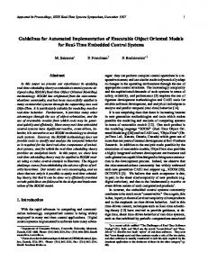
3. Executing UML Models Our approach is based on the concept of the Abstract Execution Platform (AEP). The AEP provides syntax and semantics for complete system specification based on a well-defined executable UML subset with precise execution semantics. Actual implementations of the AEP may apply inherently different techniques to implement the AEP semantics. Section 4 describes our AEP implementation given by a virtual machine on an FPGA. However, the AEP can also be implement as a complete software solution, e.g., on embedded microcontrollers. The behavioral part of the UML is based on the concepts of StateMachines, Activities, and Interactions. StateMachines invoke Activities when executing states or state transitions as Entry, Do, Exit, or Effect Activities, which in turn are composed of Actions. Transitions of StateMachines fire when an event occurs. Interactions are based on the concepts of partially ordered traces and are represented by Sequence Diagrams. Our concepts for executable UML are based on a UML 2.0 subset covering Class-, StateMachine-, and Sequence Diagrams. System specification is based on the definition of a Class Diagram with classes, their properties, and their operations. In contrast to other approaches, we consider each operation as a StateMachine and use Sequence Diagrams as an action language for describing the Activities. Note that the case of a trivial StateMachine (i.e., a single state with a single Activity) equals to the use of Sequence Diagrams for the definition of an operation. We support StateMachines with composite and simple states. Concurrent States are intentionally not supported, because concurrency is already supported through asynchronous operations that may be described by StateMachines. For events, we support timeout, interrupts, exceptions, explicit events, and the completion of the embedded Activities/Actions. Fig. 1 gives a simple controller with interrupts and timeouts as an example. Interactions are embedded as Activities and have one active object representing the currently activated instance. The Activity is described by the sequence of outgoing invocations from that active object. An example is given in Fig. 3 and will be further discussed in the next section. Asynchronous operation calls are instantiations of StateMachines. This leads to a dynamic composition of
multiple concurrent hierarchical StateMachines along the operation call hierarchy. Thus, state- and control-oriented modeling can be seamlessly combined following a fully object-oriented reactive concurrent system designs.
Forw ard
Forw ardInterrupted
exit / stopMotor() do / blink entry / startMotor(true)
entry / handleReverse() «interrupt»
after 1000 ms Completion transitions triggered by completion event
RunCompleted
after 2000 ms Backw ard exit / stopMotor() do / blink() entry / startMotor(false)
Backw ardInterrupted entry / handleReverse() «interrupt»
Fig. 1: StateMachine Example
4. The AEP Virtual Machine Our UML specifications are compiled to equivalent binary representations, which are directly executed on our Abstract Execution Platform (AEP). The AEP is realized as a virtual machine that can be implemented on different platforms, e.g., completely in software or directly in hardware on an FPGA. In their binary specifications, StateMachines are encoded as binary state-transition tables, which we denote as Executable State Machines (ESMs). Interactions defining Activities are compiled into equivalent UML bytecode.
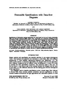
Fig. 2: AEP Virtual Machine - Architecture
The AEP virtual machine consists of the Model Execution Unit (MEU) and the Runtime Kernel (RK) as given in Fig. 2. The RK is an executable specification that on the hand is used for bootstrapping including initialization of the initial executable specification and on the other hand implements memory management, thread scheduling. The RK is executed by the MEU, which is composed of two interacting interpreters for the different parts of the binary UML representation; one for the Executable StateMachines (ESM) and another one for the Bytecode. A separate timer manages hard timeouts. The ESM Interpreter performs immediate state transitions when events occur. Currently, five pre-defined events are supported: Completion, Interrupt, Timeout, Division-by-Zero, and Memory-Overflow. When a state is entered or a transition executed, the interpreter first checks, if an Activity in form of an Interaction with bytecode is defined. If there is bytecode in the embedded Activity, the bytecode interpreter is invoked. A generated bytecode sequence typically finishes with a COMPLETE instruction, which generates a completion event. If no Activity is defined or when the final state is reached, an immediate completion event is generated. The Bytecode Interpreter executes the Bytecode in a microprocessor-like manner using an instruction pointer and a 32 bit word stack for program control. To provide a hardware-independent execution platform, the interpreter has no registers. All variables are managed on the stack. Our UML bytecode is based on a instruction set derived from the Motorola 68K family [14], which is extended for the control of the ESM interpreter and the handling of classes and their instances (cf. Table 1). Classes and interfaces are identified in our approach at runtime using unique identifiers. This allows late binding and lays the foundation for a software component architecture based on our approach like in COM [11]. Each class is a single block of binary data in memory. It essentially consists of the unique class identifier (the CLASSID), a function table for the implemented operations, an absolute pointer to the base class in memory (if any), and a reference to the linked list of implemented interfaces. Each of the interfaces, like the class itself, has a table with references to the actual method implementations. All absolute references are resolved by the RK class loader when loading a class. Because static class attributes are private in our approach, subclasses must use operations to access inherited attributes. Thus, there is no need to distinguish between local and inherited attributes, which in turn simplifies the address management. The attributes are trailing to the actual base address of the class to enable consistent access to the operation table of a class and its subclasses. Much like a C++ vtable (virtual function table), this table grows in subclasses when appending
subclass operations. It is worth noting here, that in our approach, all non-private operations are technically virtual and can be overridden in subclasses. Private operations are directly resolved by the bytecode compiler and compiled into subroutines of the bytecode. Thus, these operations are not represented in those tables. The table for each class includes three basic operations. These are the base constructor for filling the fields of an instance and two operations for initializing and finalizing the class when it is loaded or unloaded. There is no need for code relocation in our approach, since the bytecode for an operation contains only relative branches. Thus, the code is completely relative except for operation invocations. Absolute instance and class references are used for such invocations, but are obtained during runtime. Our bytecode introduces instructions to support object instantiation and destruction as well as operation invocations. The NEW instruction creates a new object allocating dynamic memory for the instance. The DESTROY instruction releases dynamically allocated instance memory. INVOKE* and FORK/JOIN execute synchronous and asynchronous operation calls using an operation identifier (the actual offset in the operation table) and the instance or interface as parameters. Synchronization is implemented by the SYNC and RELEASE instructions for obtaining and releasing a mutex semaphore on an instance. The TRYSYNC instruction is a non-blocking variant of SYNC. Three additional instructions provide explicit ESM control. The TRANS instruction performs an immediate transition to an explicitly given new state with all side effects. The EVENT instruction causes the ESM interpreter to process the event in the context of the current state hierarchy. COMPLETE causes the immediate execution of the completion transition for the current state. Finally, the CONTINUE instruction explicitly changes the execution context to the specified thread. The state of the current thread is saved on the stack before the state of the new thread is restored from the stack. This new thread will be passed to the RK scheduler implementation for immediate schedule for execution. A called operation uses the stack to create local variables and hold temporary values during nested computations. For this, the bytecode interpreter distinguishes three address spaces on the stack denoted as frames, which are created when invoking an operation (cf. Fig. 4). The Parameter Frame holds all input and output parameters. Output parameters are pushed on the stack with their default values. The Local Frame is for local variables and temporary data. Both frames have fixed sizes, which can be computed at compile time. The Pass Frame holds the designated parameters for a suboperation
call. That frame is dynamically expanded when additional parameters are pushed on the stack. The pass frame becomes the parameter frame during the invocation of that suboperation. It is extended with data for restoring the current state upon return, a reference to the parent state and, for non-static invocations, the reference to the called this instance. An additional local address space is provided for accessing local instance attributes. All instructions fetching and storing stack data refer to one of the three stack frames or this local address space. This guarantees full memory protection, but comes at the cost of a significant overhead in stack use during operation invocations as address and size of parameter and local frames have to be saved when invoking an operation.
Mnemonic Dst Src Semantics Data Movement & Stack Instructions move.[b,l,d] mem mem/im Dst ← Src push.[b,l,d] mem [-sp] ← Dst pop.[b,l,d] mem Dst ← [sp+] enter imm (Initialize local frame) Math Instructions add.[b,l,d] mem mem/im Dst ← Dst + Src sub.[b,l,d] mem mem/im Dst ← Dst - Src neg.[b,l,d] mem Dst ← 0 - Dst mul.[l,d] mem mem/im Dst ← Dst * Src div.[l,d] mem mem/im Dst ← Dst / Src mod.[l,d] mem mem/im Dst ← Dst % Src cmp.[b,l,d] mem mem/im [Flags according] Logical Instructions not.[b,l,d] mem Dst ← ~Dst and.[b,l,d] mem mem/im Dst ← Dst ∧ Src or.[b,l,d] mem mem/im Dst ← Dst ∨ Src xor.[b,l,d] mem mem/im Dst ← Dst ⊕ Src Shift Instructions asl.[b,l,d] mem mem/im Dst ← Dst > Src lsl.[b,l,d] mem mem/im Dst ← Dst > Src Control Instructions bCC disp Conditional branch bra disp Unconditional branch OO Control Instructions new mem mem/im Dst ← (instanceof Src) destroy mem (destroy instance Dst) interface mem mem Dst ← Dst as Src invoke mem Im (invoke Src on Dst) invokes mem Im (invoke static Src on Dst) invokei mem Im (interface op Src on Dst) fork mem Im (fork Src on Dst) forks mem Im (fork static) Synchronization Instructions join mem (join thread Dst) sync mem (obtain instance lock) trysync mem (lock if possible) release mem (release instance lock) ESM Control Instructions trans mem (transition to Dst) (event Dst will be event mem complete (return) Thread Control Instructions (continue Thread Dst) continue Mem
Table 1: AEP Bytecode Instruction Set
Current Instance
Attributes
this :List
First :ListNode
Last :ListNode
Parameters
Local
Result :Obj ect
Local :ListNode
Current:= getFirst()
int i:=0 loop [(i