A Design Flow for Building Automation and Control Systems Yang Yang EECS Department, UC Berkeley
[email protected]
Alessandro Pinto United Technologies Research Center
[email protected]
Alberto Sangiovanni-Vincentelli EECS Department, UC Berkeley
[email protected]
Abstract We propose a system-level design flow for building automation and control (BAC) systems. The input to the design flow is a high level description of the control algorithms given in a model-based environment such as Simulink. The input specification is translated into an intermediate format, and then automatically refined into a distributed implementation. Refinement includes optimal mapping of the functional specification on a set of computation and communication resources, and software synthesis, which generates code for each component in the mapped design while guaranteeing semantic equivalence with the original specification. Experiments with a temperature control system are presented to illustrate the flow.
1
Introduction
The building stock in the US accounts for 40% of total energy consumption and 70% of electricity consumption [18]. Limits on carbon emissions are driving new regulations that will require buildings to be energy efficient according to standards that are likely to be more stringent than the ASHRAE 90.1 [2]. The design of low energy buildings – zero energy in the ideal case – is challenging but not impossible. There are today examples of zero energy buildings [24], but they are the results of ad-hoc designs that are not easy to generalize. The design methodology used today for large buildings is top-down. Different sub-systems (e.g., mechanical and electrical) are designed in isolation by domain experts following design documents flown down after the bid process. This methodology is not suitable for low energy buildings that require interaction among architects, mechanical engineers and control engineers. Consider for instance adopting low energy solutions such as natural ventilation and ac-
Qi Zhu Intel Corporation
[email protected]
tive facade. In this case, architectural design (e.g. building orientation), the design of the mechanical equipments of the HVAC system and the design of the control algorithms cannot be done in isolation. In this new context, the design of the building automation system (i.e. the embedded processors and networks supporting the building operations, and the software running on them) is non-trivial. Control algorithms become multi-input, multi-output, hybrid and predictive, as opposed to single-input single-output controllers coordinated by simple switching conditions as today (and mainly dictated by standards). Moreover, several sub-systems such as HVAC, lighting, vertical transportation and fire and security will interact through the network to allow information sharing. In this paper we focus on a design flow for building automation systems that bridges the gap between a desirable design entry point – at a high abstraction level using model-based design tools such as Simulink [7] – and the available back-end tools able to generate low-level code. It enables the integration of models from different highlevel languages, allowing the interaction between domain experts. Further, it automatically optimizes the implementation of the control algorithms on a distributed platform by selecting computation and communication resources, and by performing code generation while meeting the specification.
2
Proposed Design Flow
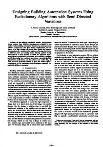
The design flow proposed in this article consists of a front-end and a back-end. The front-end is used to model the system including the control algorithms and the behavior of the environment. The back-end includes a set of tools that, given the specification of the control algorithms and a set of available computation and communication resources, automatically refines the specification into an optimal distributed implementation. The design flow is shown in Fig-
ure 1. The front-end and the back-end exchange models over an intermediate format (IF). The introduction of this intermediate layer is necessary to build a design flow which is general with respect to the user input (e.g. Simulink, Modelica [5] and LabVIEW [6]), and to the output code (e.g. C and EIKON [3]). Using an IF, pieces of the input specification expressed in different languages can be composed. This feature will hopefully foster collaboration among experts in different disciplines who could exchange models and evaluate their system taking into account the interactions with other sub-systems. The intermediate level allows targeting several implementation platforms. Building control system vendors usually provide architecture-specific languages for programming their platforms, along with tool chains for simulation, analysis, debugging and code generation. These tools can be leveraged by translating the intermediate format into the vendor specific language. Compared to providing customized design flows from each highlevel language to each architecture specific language, the intermediate format reduces the number of translators needed from a quadratic number to a linear number.
tional model to the components in the architectural model, while satisfying a set of design constraints. After mapping, code needs to be generated for final deployment. The third step of the design flow is software synthesis that starts from the mapped design and includes code generation for each processor in the distributed system, and communication interface synthesis for process communication. During code generation, we translate the functional tasks mapped onto each processor to either generic C code – if compilation tools are available for the processor – or a vendor specific language for which the code generator is usually provided. The synthesis of communication interfaces is essential to ensure the correctness of the system when the architecture platform does not directly support the semantics of the functional model. For instance, a synchronous Simulink model is not naturally supported by an asynchronous architecture that is common in building control systems. In this case, the generated communication interfaces help to ensure the synchronous functionality is correctly preserved on the asynchronous platform.
The translation process may become very involved given the expressiveness of model-based languages. Our approach to deal with the complexity of this step is to define a library of primitives at the intermediate level designed to capture a large class of building control algorithms and that can be extended by users. This library is then mirrored by equivalent libraries defined in the source languages. The set of models that can be translated into the intermediate format is the one obtained as composition of the library elements. This architecture simplifies the translation process and will be described later.
3
The back-end is responsible for mapping the functional model described in the intermediate format to the architectural model that captures the implementation platform. Specifically, the part of the functional model to be mapped is a control algorithm. The architecture platform captures computation resources (e.g. terminal control units, embedded processors and workstations), communication resources (e.g. wired buses and wireless links), sensors (e.g. temperature sensors and CCTV video cameras) and actuators (e.g. valves and switches). During mapping, the functional model is abstracted into the composition of functional tasks and messages among them. There may be constraints that come with the specification such as latency, energy and cost. The architecture platform is described in the form of a library of available architectural components that are characterized by their functionality, cost, performance, etc. The plant model is abstracted into a set of physical constraints imposed on the system. The mapping problem is cast into an optimization problem that is solved by algorithms designed to find the best mapping, with respect to a set of objective functions, from the tasks and messages in the func-
Step 1: Intermediate Format Translation
In the first step of the proposed design flow, models capturing the specification of the control algorithms and of the environment are translated into an intermediate representation. This representation is based on a language called intermediate format (IF) that should facilitate the other steps in the design flow, namely mapping and code generation. Because the type of specifications that we are interested in are in general hybrid systems [16] with multiple semantics, the IF representation may become very complex [23, 20], and thus not directly usable in the mapping and code generation steps. In the envisioned final form of our design method, IF will be manipulated and partitioned to make the mapping and code generation steps effective. In this paper that is a first step towards the ideal scenario, we restrict the intermediate format to dataflow semantics [15] which is amenable to efficient mapping and code generation. We retain the nomenclature introduced in [23] as we plan to extend this work to more general intermediate representations. In particular, each process (also called actor) is characterized by an input-output function described by a set of “equations”. When the process is scheduled to run, the equations are executed according to an order determined by an equation manager (EM) that is local to the process. The set of processes in the system is scheduled by an equation resolve manager (ERM). Processes communicate over media that, in the restricted case dealt with in this paper, are implemented as FIFOs. To enable fast translations to IF, we define a domain specific IF library for HVAC control systems in buildings, and we export the library to different specification languages.
User input
Simulink model
Simulink Building Library
Modelica model
Modelica Building Library
Legend A contains instances of B A B
Step 1 Translation
A implements B A B
Intermediate Format (IF)
A is input to B A B
Building Library Architecture Platform
Step 2 Mapping
Mapped design
Step 3 To vendor-dependent language
Step 3 Communication interface synthesis
Implementation
Vendor -dependent control algorithm description
Vendor -provided code generation
Interface code
Code for Pn
Space of data models
Repository
Process
Code for P 1
Figure 1. Design flow for building automation and control We reviewed 71 HVAC-related component models in the GPL language from Johnson Controls [8], 70 in Automated Logic EIKON language [9], 42 in Honeywell Spyder [10], and 59 in the HVAC library defined by the Lawrence Berkeley National Laboratory [26]. Based on these information, we defined a set of basic components used in HVAC control systems and the corresponding processes in the IF, including: • Mathematical functions: ADD, SUB, MUL, DIV, ABS, SQRT, MIN, MAX, SUM, AVG, INTEGRATOR, DERIVATIVE, GAIN. • Logic functions: INV, AND, OR, XOR. • Signal processing functions: SWITCH, LIMIT, SPAN, COMP, PID. • Time functions: TIME, DATE, DELAY, TIMER, OCCUPENCYSCHEDULE. • Psychrometric functions 1 : ENRH, WBTRH, DPTRH, ENW, WBTW, DPTW. As an example, the PID component in our IF library is described as follows: PID { parameter double Kp, Ki, Kd, Kc; parameter bool outMin, outMax; port double setPoint, var, out; equations{ err = setPoint - var; sum = Kp*err + Ki*int(err) + Kd*dev(err) + Kc*diff(out,sum); out = (sum>outMax)*outMax + (sum