ing automation systems, the interoperability of installations from different vendors constitutes a significant problem for planners, construction companies and ...
SENSORCOMM 2012 : The Sixth International Conference on Sensor Technologies and Applications
Generic Control Architecture for Heterogeneous Building Automation Applications Armin Veichtlbauer, Thomas Pfeiffenberger, Ulrich Schrittesser Advanced Networking Center Salzburg Research Forschungsgesellschaft m.b.H. Salzburg, Austria {firstname.lastname}@salzburgresearch.at
Abstract—In home automation systems, and even more in building automation systems, the interoperability of installations from different vendors constitutes a significant problem for planners, construction companies and users. A generic communication infrastructure on All-IP basis, which can be used by several building automation applications like lighting, heating, ventilation, air conditioning (HVAC), access control, evacuation support, etc., can help to reduce costs during the whole building lifecycle. These applications perform control tasks with distributed sensors and actuators; many of these tasks are highly safety and security relevant. During the project Robust Facility Communication (ROFCO) we explored the requirements of a generic, but robust communication infrastructure in a building automation environment, designed and implemented a prototypical solution, and conducted a validation trial at the site of our project partner Techno-Z Salzburg. Index Terms—Control Systems; Building Automation; Supervisory Control and Data Acquisition Systems; Generic Infrastructures.
I. I NTRODUCTION Home automation (HA) and building automation (BA) systems usually consist of a variety of different sensors and actuators (field level) as well as control devices (automation level), which are interconnected via several field bus technologies, like European Installationi Bus (EIB), Modbus, Local Operating Network (LON), Digital Addressable Lighting Interface (DALI), etc. Alternatively, radio or powerline communication may be used to reduce mounting costs, especially for older surroundings. The management level, if existing, supervises and controls the automation tasks; in many cases this is realised via web-based services in order to allow a remote control of the automation applications [1]. The market for HA and BA solutions has been rapidly growing in recent years; yet in most cases buildings are not equipped with an integrative solution from a system provider, but with individual solutions for different building automation applications [2]. The lack of interoperability of these heterogeneous solutions prevents the shared use of existing equipment, e.g., information from access control systems (like the number of persons in certain parts of a building) could be a valuable input for evacuation support systems in cases of danger, but is usually not accessible due to the proprietary nature of both solutions. Our approach to overcome these drawbacks was to use open protocols and generic standards at every communication
Copyright (c) IARIA, 2012.
ISBN: 978-1-61208-207-3
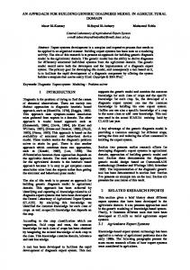
layer and at every level of the automation pyramid. Basically we intended to integrate different applications and different infrastructures via a convergence layer on All-IP basis, which we referred to as “X-Model”. Yet it was quite obvious that some additional functions have to be added to a working solution. For instance, by ensuring interoperability in the way that applications should have access to the whole network and sensor/actuator infrastructure, the danger of potential misuse arises; this implicates the necessity to define appropriate security means in order to avoid damages. Thus the main goals of the generic architecture, which we have developed during the funded project “ROFCO” [3], is to ensure dependability, i.e., robustness, reliability, availability, safety and security [4]. Based on the requirements of a distributed heterogeneous BA system we defined three layers for for our generic ROFCO architecture, as shown in Fig. 1 [5]: • An infrastructure layer, which embodies all the necessary networking functionalities for our control architecture • A middleware layer, which provides appropriate robustness, reliability, availability, safety and security means on an end-to-end basis • An application layer, which is responsible for the distributed control tasks of the applications using the ROFCO architecture The application layer comprises several control logics (e.g., implemented with Programmable logic controller (PLC) or Direct Digital Control (DDCs)) at automation level as well as supervisory tools for end users (so called “SCADA” systems) at the management level. In this paper, we concentrate on the infrastructure and middleware layers of this generic BA control architecture. We start with an overview of the scientific state-of-the-art and an assessment of existing market-ready solutions, in Section II. In Section III, we describe the communication infrastructure and the testbed we set up at the Techno-Z in Salzburg. This section is followed by Section IV, a description of the protocol functionalities we used in order to realise a robust and reliable communication system, and of the safety and security means we integrated in the prototype [6], constituting the ROFCO middleware. The subsequent section explicates the validation trials we conducted with our prototype, based on the use cases we defined for blinds and lighting control. We conclude
148
SENSORCOMM 2012 : The Sixth International Conference on Sensor Technologies and Applications
Fig. 1.
ROFCO Architectural Concept [5]
with the findings derived from the conducted system trials in Section VI and an outlook in Section VII to potential followup research topics and exploitation activities. II. R ELATED W ORK The heterogeneity of BA solutions has been identified as a potential barrier for BA technologies since about the turn of the millennium [7] [8]. Big vendors may offer integrative solutions, e.g., “Total Building Solutions” from Siemens [9] or “Raumtalk” from ABB [10], yet based on proprietary communication and control technologies. Several research teams have tried to overcome this barrier by proposing interoperability features for BA systems, e.g., via gateways between field bus technologies [7], or by providing complete BA architectures for interoperable BA applications [1] [11]. For communication infrastructures, the idea of using the IP standard is not new [8]. A fully integrated approach however requires solutions for the whole automation pyramid, i.e., on every level of the control process: setting and getting values at field level, performing a control task at automation level, and supervising this at management level. A standardised middleware for that purpose needs to provide more than just IP communication; especially a generic modelling of BA objects and variables is inevitable. For that purpose, the American Society of Heating, Refrigerating and Air-Conditioning Engineers (ASHRAE) defined the BACnet standard [12]. With BACnet, complete BA environments could be built based on one generic technology [13]; yet in reality this approach has several drawbacks: • The calculatory power required by the BACnet protocol suite is rather high, thus many field layer devices are not able to implement the BACnet stack, i.e., these devices have to be integrated via gateways. • The support of the very common IP protocol is weak, as it is not part of the native BACnet stack. A work around named BACnet-IP is provided, i.e., basically a tunneling of BACnet messages through an IP network. • State-of-the-art network management concepts like QoS (Quality of Service) are not supported with BACnet, which is especially critical with the use of safety or security relevant control applications (e.g., evacuation
Copyright (c) IARIA, 2012.
ISBN: 978-1-61208-207-3
Fig. 2.
ROFCO Network Infrastructure
support) [14], as they require very high dependability standards, especially concerning availability of communication infrastructure. The definition of the OPC-UA [15] standard, which is already commonly used for the control of industrial production [16], may help to overcome these shortages. By using OPCUA in combination with TCP as transport protocol we can integrate IP networks and all the QoS mechanisms existing for the TCP/IP protocol stack. Some academic implementations of OPC-UA for BA systems are already existing, e.g., the solutions of the TU Vienna [17]. Yet the requirements for end systems still are rather high, resulting in the necessity to provide gateways to legacy systems containing older devices with not sufficient calculatory power. There are some further research activities in the area of BA systems. These include topics as safety and security [18], control strategies and technologies [19], as well as performance issues [20]. Especially the safety and security topics are of notable interest in order to produce saleable solutions, as open systems always are always prone to outages [21] in consequence of improper use or even planned attacks. III. I NFRASTRUCTURE The goal of our work was to create a generic BA architecture which allows for easy integration of dependability, i.e., providing generic interfaces for different BA applications, including visualisation and supervisory control. For that purpose we defined an IP based network backbone (Fig. 2), which connects all legacy components via gateways. SCADA systems however, e.g., “Zenon” from our project partner Copa-Data, can be integrated natively, i.e., as a part of the ROFCO robustness domain. This is realised by providing an open software interface containing IP sockets. Due to this openness several SCADA manufacturers may share different end devices and data servers; thus our solution provides a holistic concept to integrate global dependability means, opposed to currently available island solutions.
149
SENSORCOMM 2012 : The Sixth International Conference on Sensor Technologies and Applications
Fig. 3.
ROFCO Testbed
A. Testbed Network In order to test the feasibility of our concept, we built a prototypical solution, which we tested at the site of the project partner Techno-Z Salzburg. Fig. 3 shows the network topology of the ROFCO testbed, which expanded over three buildings (3, 10, 12) at the TechnoZ. It was basically composed of two class C IP subnets: • •
Subnet I is the management subnet of the Techno-Z used in Building 10 and 12 Subnet II the control subnet from the ROFCO laboratory at Building 3
In both subnets we used switches with two redundant GBIC ports, thus connecting both subnets with redundant fiber connections between Building 3 and Building 10. A third switch in the ROFCO laboratory builds the interface to the various ROFCO servers. As part of the robustness concept these (manageable) switches are configured with the spanning tree (STP) mechanism. Due to the ROFCO security concept two Virtuel Local Area Networks (VLAN) are configured on these three main switches, i.e., the devices connected to these switches can be run in both VLANs. Both subnets are connected with respective company networks (Techno-Z and Salzburg Research) via a router/firewall
Copyright (c) IARIA, 2012.
ISBN: 978-1-61208-207-3
combination. For further security issues an internal sniffer was installed to monitor the traffic inside the control and management subnets. Both functionalities, along with an intrusion detection system, can be performed by using the “MFSecurity-Gateway” from the project partner Underground8. B. Testbed Components Each building at the Techno-Z Salzburg is equipped with different BA systems, e.g., a Somfy system to control blinds and a Sauter system to control the lighting and all HVAC components via EIB/KNX. In the following, we will describe those components which we have researched as part of the ROFCO testbed. •
Somfy Control, Building 10 To control the blinds of the Buildings 10 to 15, the Somfy blind control is separated into three zones. In zone one, a single Somfy control system at the 3rd Floor regulates the whole blinds for Building 10. At this place a controller of our project partner cTrixs was installed, which serves as gateway between the blind circuit (over relay control and digital I/Os) and the Ethernet wiring.
•
Facility Management Room, Building 12 For managing the BA systems for the Techno-Z complex,
150
SENSORCOMM 2012 : The Sixth International Conference on Sensor Technologies and Applications
a control computer is situated in the facility management room in Building 12 on the ground floor. On this computer e.g., the Sauter BA system (which includes the HVAC capabilities) or the Designa access control system are visualized. Also the central fire indicating equipment is located in this room. •
Engineering Room, Building 12 The Sauter BA system, the EIB lighting system and the central switch are located in the engineering room at the ground floor in Building 12. The entire building is wired from this switch. For the ROFCO network a port on the central switch was reserved and activated. There is also the possibility to configure VLANs on this Catalyst 2950 switch. A second cTrixs controller provides the interface to the EIB lighting in the congress room in Building 12; it is connected to the central switch and to the EIB bus to control the lights at the ground floor.
•
ROFCO Laboratory, Building 3 The laboratory is equipped with a cTrixs Application Server (CAPS) and a Zenon machine with master/backup function. On the Zenon Display the use cases we considered in ROFCO (lighting and blind control) can be visualised and controlled. The CAPS is used as a central server for the cTrixs controllers.
At the ground floor in Building 12, the lighting is not fully represented in the current building management. Thus the lighting data points and also the blinds functions in the ROFCO Showcase are implemented and visualised on the CAPS and Zenon surfaces. In Building 3, the blinds are handled by an IP-enabled cTrixs controller, but in opposition to the solution in Building 10, the connection is done directly via analog outputs and relays, and not via EIB. A Wireless Local Area Network (WLAN) bridge has been installed to transmit data to the controller. IV. M IDDLEWARE The ROFCO Middleware layer (RML) is used to establish a dependable end-to-end communication between different entities (Fig. 1). It supports the independent distribution of control information between different end systems. A. Dependability Requirements A main requirement of the ROFCO system is to use commercial off-the-shelf (COTS) hardware. As the ROFCO hardware must support high reliability and calculable availability, the mean time between failure (MTBF) and the mean time to repair (MTTR) metrics of each hardware device must be known in order to derive the overall availability of the ROFCO system. For authentication and authorisation well established mechanisms have to be used, such as ITU-T X.501 [22] or IETF RADIUS/DIAMETER [23] [24]. Encryption is a further main requirement to establish a secure connection over a distributed heterogeneous communication system. For the underlying network functionalities classical network devices like
Copyright (c) IARIA, 2012.
ISBN: 978-1-61208-207-3
CISCO switches and routers are used. Address management and routing are based on IP [25], routing metrics [26] must be supported. B. ROFCO Entities and Roles After determining the requirements for our prototype we compared potential technologies for our intended solution and decided for the use of OPC-UA as generic communication and management protocol. Using the free OPC-UA stack from the OPC foundation [27] we implemented the basic functionalities prototypically. OPC-UA can be used as a good base to create a generic control architecture, yet in order to integrate the intended dependability means, we had to define functionalities, which go beyond an ordinary OPC-UA implementation. The entities we defined for that purpose and their specific tasks in the ROFCO system are listed in the following: • Client • Server • Registrar • Mediator The Client communicates and exchanges information with the Server. To be part of the installed ROFCO system the Client and all defined parts must register at the Registrar. To communicate with a non-ROFCO entity or device the Mediator maps the information between ROFCO entities and nonROFCO entities. The Server supports the possibility to present the information in OPC-UA style. The Registrar provides interfaces for authentication and authorisation to the ROFCO system. To integrate QoS, service classes are defined for the different requirements of the supported applications. C. Registration and Authentication Process ROFCO devices, such as sensors, actuators, controllers, etc. must register to a ROFCO Registrar. This is necessary to exchange session keys and validate user certificates. Each ROFCO device sends its valid user identification to the corresponding ROFCO device. The corresponding ROFCO device can verify the received user certificate. If the ROFCO device does not trust the user it can check the certificate by sending it to the Registrar. Within the registration process the access levels of ROFCO devices are managed. In the ROFCO show case some ROFCO devices have limited access level to some resources. Fig. 4 shows a scheme of the registration process, which has to be performed by all devices taking part in the ROFCO system. D. Quality Assurance To identify potential failures in the design and the application life cycle in the whole ROFCO system a procedure called failure modes and effects analysis (FMEA) has been used. The FMEA gives an overview about which parts of the ROFCO system have the most important impacts on failure. The ROFCO system supports the dependable operation of a communication infrastructure. To detect misbehaviour of the end systems, keep alive messages are sent during normal
151
SENSORCOMM 2012 : The Sixth International Conference on Sensor Technologies and Applications
Fig. 4.
ROFCO Registration Process
defined. Like in an agile software development process, each single use case had to be validated. Based on the verbal description and the UML Use Case Diagram of each use case we defined the respective tests. Each test definition had some attributes, such as test description, pre-conditions and postcondition, as defined in [30]. The whole ROFCO system, as described above, was validated in the ROFCO validation trial. All involved stakeholders and project partners have prepared the defined use cases to validate the ROFCO system. During some pre-tests, some misconfigurations in the controller setup could be identified and fixed. The validation trial showed the interworking of a heterogeneous building automation system as expected. VI. C ONCLUSION
Fig. 5.
ROFCO Use Case Blinds Maintenance
operation. Messages sent between different devices are signed and authenticated. Anomaly detection is a further goal of the ROFCO architecture to find faulty messages and traffic in the system. With traffic monitoring this traffic can be detected and isolated from the system. V. VALIDATION To develop a dependable system it is a basic precondition to use well established and standardised methods for verification and validation. These methods are based on several different standards, e.g., IEC 61508 [28]. In this paper we concentrate on the validation steps of the ROFCO project. The validation strategy is based on pre-defined use cases. During the course of the project these use cases were adapted to needs and requirements. Thus we have achieved an iterative product life cycle process during the project lifetime in order to enhance the quality of the ROFCO architecture. The requirement engineering process and the product life cycle process are based on standards [29]. As an example for the whole validation mechanism in ROFCO, Fig. 5 shows the use case of the maintenance sequence of sun-blinds. User stories have been used to describe the use case in such a way, that all stakeholders could understand the requirements and the interaction with the ROFCO system. For requirement gathering the verbal description of the use case and the discussion with the stakeholders improved the understanding for the developers. For validating the ROFCO system different steps were
Copyright (c) IARIA, 2012.
ISBN: 978-1-61208-207-3
As a result of our validation trial we proved the feasibility of our approach, as we were able to access the control devices using different OPC-UA clients. We were able to implement getter and setter functions for the data points in different building units (lighting, blinds). Furthermore, we developed a robustness concept based on availability calculations according to IEC 61508 [28] functional safety standard and assessed the system relevant risks with an FMEA. A possible barrier for a wide adoption of our approach in future commercial solutions are the relatively high requirements on the used devices. In order to be able to proceed all the session and rights management data as well as the OPC stack the devices need a certain minimum of calculatory power; for practical reasons this can not be guaranteed in all cases. Here this can be counteracted by the use of gateways to those legacy systems, which are not able to implement a native OPC connection, yet this limits the beneficiaries of our system to a more narrow system border. However, future developments have to be observed accurately, as the progress of calculatory power in embedded devices may make this drawback obsolete in a few years. VII. F URTHER W ORK For safety and security relevant applications like evacuation support, not only principle concepts need to be shown, but solutions have to be provided which meet certification requirements. In parts such standards are existing (e.g., for certification of evacuation systems) but the whole process of installing and maintaining different applications in a building environment is not standardised as such, i.e., changing the set up of any other linked automation subsystem would enforce another accreditation for the security relevant application, as the environment of the security relevant subsystem has changed. This is a major obstacle to install interoperable systems and one of the reasons why integrated HA/BA solutions are still rare. An interesting research field is emerging through the current developments in the smart grid sector. The establishment of communities which are sharing energy resources generates many questions regarding not only security, but also privacy, billing, optimisation of resource usage, and thus controlling
152
SENSORCOMM 2012 : The Sixth International Conference on Sensor Technologies and Applications
not only single buildings but bigger unions. Especially the integration of a distributed energy control network with existing solutions in HA/BA is a considerable challenge. ACKNOWLEDGMENT The work described in this paper was conducted during the project “Robust Facility Communication” (ROFCO) funded by the Austrian Federal Ministry for Transport, Innovation and Technology (BMVIT). R EFERENCES [1] K. Charatsis, A. Kalogeras, M. Georgoudakis, J. Gialelis, and G. Papadopoulos, “Home / Building Automation Environment Architecture Enabling Interoperability, Flexibility and Reusability,” in Proceedings of the IEEE International Symposium on Industrial Electronics 2005 (ISIE 2005), vol. 4, Jun. 2005, pp. 1441–1446. [2] F. Ferreira, A. Osorio, J. Calado, and C. Pedro, “Building Automation Interoperability – A Review,” in Proceedings of the 17th International Conference on Systems, Signals and Image Processing (IWSSIP 2010), 2010, pp. 158–161. [3] Salzburg Research Forschungsgesellschaft. (2012) ROFCO – Robust Facility Communication. Accessed: 2012-06-19. [Online]. Available: http://www.salzburgresearch.at/en/projekt/rofco en/ [4] G. Panholzer, A. Veichtlbauer, P. Dorfinger, and U. Schrittesser, “Simulation of a Robust Communication Protocol for Sensor Data Acquisition,” in Proceedings of the 6th International Conference on Wireless and Mobile Communications (ICWMC 2010), Valencia, Spain, Sep. 2010, pp. 145–150. [5] A. Veichtlbauer and T. Pfeiffenberger, “Dynamic Evacuation Guidance as Safety Critical Application in Building Automation,” in Proceedings of the 6th International Conference on Critical Information Infrastructure Security (Critis 2011), Lucerne, Switzerland, Sep. 2011. [6] C. Probst, “Konzeptionierung eines Benutzermanagements f¨ur den Zugriff auf vertrauliche Daten von IP f¨ahigen Sensornetzen,” May 2010, in German. [7] J. P. Thomesse, “Fieldbuses and interoperability,” Control Engineering Practice, vol. 7, iss. 1, pp. 81–94, Jan. 1999. [8] E. Finch, “Is IP everywhere the way ahead for building automation?” Facilities, vol. 19, iss. 11/12, pp. 396–403, 2001. [9] Siemens AG. (2011) Total Building Solutions f¨ur intelligente Geb¨aude – Siemens Building Technologies. Accessed: 2012-06-19. [Online]. Available: http://www.industry.siemens.de/buildingtechnologies/de/de/ total-building-solutions/Seiten/total-building-solutions.aspx [10] ABB Asea Brown Boveri Ltd. (2012) Raumtalk – Building Automation over IP. Accessed: 2012-04-11. [Online]. Available: http://www. abb.at/cawp/deabb201/24d156e58bc98443c125720b0025238d.aspx [11] W. Granzer, W. Kastner, G. Neugschwandtner, and F. Praus, “A Modular Architecture for Building Automation Systems,” in Proceedings of the 6th IEEE International Workshop on Factory Communication Systems (WFCS ’06), Jun. 2006, pp. 99–102.
Copyright (c) IARIA, 2012.
ISBN: 978-1-61208-207-3
[12] American Society of Heating, Refrigerating and Air-Conditioning Engineers Inc., “BACnet - A Data Communication Protocol for Building Automation and Control Networks,” ANSI/ASHRAE Standard 1352004, 2004. [13] D. Snoonian, “Smart buildings,” Spectrum, IEEE, vol. 40, pp. 18–23, Aug. 2003. [14] U. Schrittesser, “Synthese von redundanten vermaschten WLAN,” Jun. 2008, in German. [15] CAS. (2010) OPC Unified Architecture. Accessed: 2012-0619. [Online]. Available: http://www.commsvr.com/UAModelDesigner/ Index.aspx [16] W. Mahnke, S.-H. Leitner, and M. Damm, OPC Unified Architecture. Springer-Verlag Berlin Heidelberg, 2009. [17] A. Fernbach, W. Granzer, and W. Kastner, “Interoperability at the Management Level of Building Automation Systems: A Case Study for BACnet and OPC UA,” in Proceedings of the 16th IEEE Conference on Emerging Technologies and Factory Automation (ETFA ’11, Sep. 2011. [18] W. Granzer, W. Kastner, G. Neugschwandtner, and F. Praus, “Security in Networked Building Automation Systems,” in Proceedings of the 6th IEEE International Workshop on Factory Communication Systems (WFCS ’06), Jun. 2006, pp. 283–292. [19] T. I. Salsbury, “A Survey of Control Technologies in the Building Automation Industry,” in Proceedings of the 16th IFAC World Congress, vol. 16, part 1, Prague, Czech Republic, Jul. 2005. [20] S. Makarechi and R. Kangari, “Research Methodology for Building Automation Performance Index,” International Journal of Facility Management, vol. 2, no. 1, 2011. [21] C. Probst and A. Veichtlbauer, “Security Features of a Generic Sensor Data Acquisition System,” in Proceedings of the 6th International Symposium on QoS and Security for Wireless and Mobile Networks (Q2SWinet 2010), Bodrum, Turkey, Oct. 2010. [22] International Telecommunication Union. (2008) X.501. Accessed: 2012-06-19. [Online]. Available: http://www.itu.int/rec/T-REC-X.501 [23] C. Rigney, A. C. Rubens, W. A. Simpson, and S. Willens, “Remote Authentication Dial In User Service (RADIUS),” IETF RFC 2865, Jun. 2000. [24] P. Calhoun, J. Loughney, E. Guttman, G. Zorn, and J. Arkko, “Diameter Base Protocol,” IETF RFC 3588, Sep. 2003. [25] J. Postel, “Internet Protocol,” IETF RFC 791, Sep. 1981. [26] R. Baumann, S. Heimlicher, M. Strasser, and A. Weibel. (2007, Feb.) A survey on routing metrics. TIK Report 262. Accessed: 2012-06-19. [Online]. Available: http://www.baumann.info/public/tik262.pdf [27] OPC Foundation. (2012) OPC – The Interoperability Standard for Industrial Automation & Other. Accessed: 2012-06-19. [Online]. Available: http://www.opcfoundation.org [28] International Electrotechnical Commission (IEC). (2012) Functional safety and IEC 61508. Accessed: 2012-06-19. [Online]. Available: http://www.iec.ch/functionalsafety [29] “Systems and software engineering - software life cycle processes,” Tech. Rep., 2008, Accessed: 2012-06-19. [Online]. Available: http://dx.doi.org/10.1109/IEEESTD.2008.4475826 [30] “IEEE standard for software test documentation,” Tech. Rep., 1998, Accessed: 2012-06-19. [Online]. Available: http://ieeexplore.ieee.org/xpls/abs all.jsp?arnumber=741968
153