The Design and Implementation of a Linescan Camera based Real-time Image Scanning System Dong Hyun Jeong1, Young Rin Kim1, Kang Moon Lee2, Kwang Won Jin2, Chang Geun Song1 Hallym University1 M.O.I. Co., Ltd.2 Abstract: In this paper, real-time image scanning system is designed using linescan camera. The system is especially designed to diagnose and analyse condition of tunnels such as crack widths using the captured images. The system consists of two major parts, the image acquisition system and image merging system. To save the scanned image data to storage media in real-time, the image acquisition system has been designed with two different control modules and management modules. The control modules are in charge of the hardware device control and the management modules handle system resources so that the scanned images are safely saved to the magnetic storage devices. The system can be mounted to various kinds of vehicles. After taking images, the image merging system is used for generating an extended image by combining saved images. Several tests were conducted in laboratory as well as in field environment. In the laboratory simulation, both systems are tested in several times and upgraded. In the field-testing, the image acquisition system is mounted to a specially designed vehicle and images of the interior surface of the tunnel is captured. The system is successfully tested in a real tunnel with a vehicle of speed 20 km/h. The captured images of the tunnel condition, including cracks, are as vivid as the view an expert could assess seeing through his/her eyes. Keywords: Linescan camera, File caching, Machine Vision.
1
Introduction As the technology of display and graphics systems have been developed, many
researchers have devised new equipments. Linescan camera is one of the newly devised equipments for the purpose of taking motion pictures in real-time. Our designed system adapts the linescan camera for taking shots of tunnel images. Until now, many tunnel experts have been going into tunnels to inspect the condition of tunnels by keeping track of crack width and growth. If they find that the crack size and width are above of the prescribed standards or the crack growth rate is faster than usual, they activate contingency plans. As far as diagnosis is concerned, experts have done their work well. However, they sometimes experienced serious injuries during inspection on their necks and eyes since they spend a lot of time inspecting the cracks in usually dark and hazardous conditions. In this paper, a highly efficient system is designed for taking tunnel images in real-time. With this system, people only need to drive the system-mounted vehicle to capture tunnel images. After the drive, they diagnose the status of tunnels at their convenience place. Also 1 2
email: [dhjeong, yrkim, cgsong]@hallym.ac.kr email:
[email protected],
[email protected] 1
the crack growth can be measured every year by accumulating data and analysing them periodically. It is a safe and efficient way compared to the conventional method of working on human perception alone in a dark and hazardous tunnel. The system consists of two sub-systems: image acquisition system and image merging system. The image acquisition system captures tunnel images and the image merging system combines the consecutive images to generate one extended image of the tunnel wall. The image acquisition system consists of control and management modules. The control modules are in charge of controlling the hardware devices and the management modules handle the system resources to get images without system lag. The image acquisition system uses magnetic disk (hard disk) instead of tape disk as a storage device for saving images. Though the tape disk accommodates large storage capacity, it is not fast enough to save images in real-time mode. But, magnetic disk gives enough amounts of storage capacity and high-speed file transfer rate. Therefore, the system uses the magnetic storage disk instead of the tape disk. The system is tested on two different experimental environments: in the laboratory and in the field. In the following section, we review previous related researches on other similar systems. A brief explanation of the implemented system is as follows. Experimental environments and results are described in the next section. Finally, our conclusion and future works will be discussed.
2
Previous work Linescan camera has been used in a lot of fields, especially in vision-based fields. Also
it is broadly used in manufacturing companies where it is used for finding errors by checking their products in real-time. Several researchers designed a special-purpose vehicle for generating 3D models. While driving the vehicle, 3D buildings are generated and images that were taken are used for making texture maps [4][6][7][8]. A few companies make tunnel image acquiring systems. Most of them use infrared cameras to get images. Even though the system has already been used for diagnosing the crack width in European countries, the infrared camera cannot give high-resolution images. Therefore, some countries cannot use the foreign image acquisition system for diagnosing tunnel conditions because of their highly strict standards. Also some researchers have designed tape disk based on the tunnel image acquisition system. But the system cannot guarantee real-time image capturing [2][3][5]. 2
3
System Architecture
3.1 Image file format Most of digitized images are saved as an encoded or compressed file format to reduce disk storage usage. There are two different compression techniques such as lossless and lossy compression. In late 1970s, research about lossless image compression techniques were begun based on statistical and dictionary methods of compression. However, such types of compression did not tend to perform well on photographic images. Therefore people tried to find more efficient methods. By the late 1980s, extensive researches had been done by taking the advantage of known limitations of the human eye resulting in lossy compression. The method shows the high performance even if it utilizes lossy compression. Currently the lossless and lossy compression methods are well designed for reducing the disk usage. Even if the compressed images are efficient for reducing storage usage, for the case of diagnosing or analysing purposed images such as medical and crack or tunnel images, the images must not have lossy information. The lossy information can cause serious problem for diagnosing the status or making a decision of safety. In our flight test, the system is designed by taking one of the lossless image compression methods. The designed system was tested in several experimental settings. During the test, we found that even though the compression algorithm reduced storage usage effectively, it affected other system modules because of a fairly expensive computation. Hence, the system has been modified without applying the compression method. The system uses RAW image file format. In contrast to BMP file format, the RAW image file format does not have any header information. In our system, the header information does not have to exist because the system already knows image width, height and the color information. The system generates a lot of high-resolution digital images during the operation. Therefore, without header information, it is possible to reduce storage usage on devices with limited storage capacity.
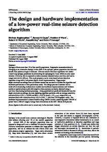
3.2 Linescan camera configuration Linescan camera consists of optical and electric systems. Figure 1 shows the camera block diagram and a used linescan camera.
3
Interface
Processed Image Data
Embedded Processing Electronics Digital Image Data
CCD Image Sensor
Analog Image Data
AD Conversion Electronics
Fig 1. Camera Architecture Block Diagram (left) and AViiVA M2 CL (right) Whenever the Optical camera (CCD image sensor) takes images, it sends the captured analogue data to the electric parts of system in order to convert to digitized format. After having been converted to digitized data, they are directly sent to PC-based image grabber board. Finally the data can be extracted using software systems from the grabber board. Both the grabber board and the linescan camera have their own attributes, which can be directly changed using serial communications. Changing the attributes is necessary while taking pictures because if the capturing speed of the linescan camera is not directly adjusted depending on the vehicle speeds, the tunnel image will be captured improperly. The used linescan camera and the grabber board’s specifications are shown below: Linescan Camera: AViiVA M2, ATMEL Corporation. Data rates: 60Mpixels/s Grabber board: X64-CL, CORECO iMAGING Corporation. Data rates: 255MB/s per input channel
The grabber board is mounted on the PCI slot of the PC. And the camera is linked to the input channel in the grabber board. To cover wider surface area of the tunnel walls, the linescan camera uses wide-angle lens.
3.3 Image Acquisition System The overall system consists of two different sub-systems: the image acquisition system and the image merging system. The image acquisition system saves the scanned digital image to a local storage device. It saves each image per frame labelled with sequence numbers. Each saved image size is 4096 by 256 pixels. The image merging system reads locally saved
4
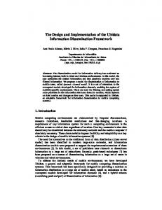
images and generates an extended image by linking those images in order to reference or diagnose crack width and/or spacing. System control
OS & Device control
Disk control
Disk space control
File Management
File copy & saving
Control module
Management module Memory Management
Memory allocation & copying
Fig 2. System architecture of image acquisition system Mainly the image acquisition system is designed with two modules such as control and management. The control module controls hardware devices such as the camera and storage devices. And the management module is in charge of memory allocation and image saving. The control module has two parts such as system and disk control. And the management module consists of two different managing parts such as file and memory management. The system control, one of the control modules, is responsible for controlling CPU preemption of each process, memory consumption and image acquisition device (grabber). If a process preempts a lot of CPU resources itself, it can affect to the overall system performance. Also if the system performance is getting worse, previously captured images can be damaged or overwritten. To prohibit the CPU preemption and protect the captured data, the system control checks the status of the system and stops capturing if necessary. The disk control handles each mounted storage devices. In fact, even if a tape storage device can give high amounts of storage capacity, it does not guarantee high-speed data transfer rate. Therefore the system uses magnetic storage devices instead of using a tape disk. Our system is designed to have four magnetic storage devices. Each has 200GB of storage capacity. While capturing process is progressing, the system generates large amount of images. Therefore, it needs a large amount of storage capacity. Usually there are four IDE computer drives in common personal computers, so it is possible to adapt four magnetic storage devices. Therefore, the system supports up to 1TB of total disk storage capacity. The disk control manages each storage device and switches to other device if there is not enough free space in a currently used device. Direct image acquisition is the most important part of the system. Whenever the linescan camera scans tunnel surfaces, the scanned images directly go to the main memory of grabber board in digitized format. To make the image acquisition system operate in real time,
5
it directly saves the scanned images located in memory to the local magnetic storage devices. The file and memory management modules control each process and make sure the digitized image is saved to storage device safely.
File Management
Memory Management
Processed Image Data
Processed Image Data Queue buffer
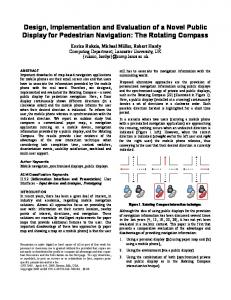
Fig 3. System management Figure 3 shows the diagram of system management subparts. Generally, the grabber board supports a mechanism of DMA (direct memory access). With the DMA, the scanned image data in grabber board can be directly copied to memory (RAM) in PC and then copied to magnetic storage disk (hard disk). But saving images to hard disk is much slower than copying between the grabber board and the RAM in the PC. To manage or compensate for the speed difference, a buffer has to exist between two devices. The buffer is designed like a linked list. Whenever the images are copied from grabber board, they are directly moved or inserted to queue buffer. The file management always monitors the incoming data in queue buffer. When data is found in the queue, it performs copy operation for saving the data to the local magnetic storage devices. And after the completion of saving procedure, image data is deleted from the queue buffer. In our first version of the system, it is designed with a circular queue buffer having ten slots. Each slot can store 4096x256-pixel images. The circular queue works well but causes some problems in several computer systems. The reason is that if the system clock speed is not fast enough to process the file I/O copy operation, the image data might be overlapped. Therefore, a dynamic linked list queue is adapted. The list can be spanned or shortened dynamically depending on the amount of image data to be processed. The file management saves the scanned image data to local storage devices. Broadly used file saving mechanisms (standard I/O operations) are adapted in our first version of system. Even if the image saving procedure does not require much processing time, when the system is tested in laboratory experimental settings, a lot of system overhead, unwanted CPU preemption, increase of queue buffer size and even system shut down occurs. To make the system more reliable, the system is modified adopting the file caching method. Figure 4 shows the system flow of file caching.
6
System Cache
Disk
Process Address Space File
Fig 4. Disk access using system cache [1] The file caching method provides the mechanism through which the system reads data file from system cache area instead of reading from the physical disk. Correspondingly, it can write data to the system cache rather than the disk. Originally caching occurs under the control of the cache manager that operates continuously while the operating system is running. Before performing the save operation, the file management creates an exact amount of slot for the file by referencing the free space of local storage disk. If there is not much free space in storage device, it switches to another physical device and creates a slot in system cache. Then, the scanned image data is written to a slot in system cache. The written data in system cache is also written to the physical disk at given intervals determined by the operating system. While saving image data to the local storage device, the file management create subdirectories and maintains not exceeding a 1000 image data per each sub-directory. If more than 1000 images are allocated to the same directory, it may seriously degrade OS performance. The system always spends a lot of time by checking whether the file with same name exists or not.
3.4 Image Merging System All the scanned tunnel image data are saved in different sub-directories. Each slice image has 4096x256 pixels. The sliced images have to be merged into a large one for diagnosing the inner surface of the tunnel. With the sliced image data, it is hard to measure the crack width and to judge the safety since a crack line might be divided and displayed in several consecutive slice images. The image merging system also uses the file caching mechanism like the image acquisition system. Even though the image merging system does not require fast I/O access, however the file caching is necessary for saving a large extended image without significant system delay. If the system uses the standard I/O operations for saving the merged image data
7
to storage device, it takes a lot of time and overhead. Therefore, to improve the speed of saving files, the system is designed adapting the file caching mechanism.
Fig 5. Image acquisition system (left) and Image merging system (right) Figure 5 shows the image acquisition system and the image merging system. Both images are taken in laboratory experimental settings. The image acquisition system shows currently scanned images and some useful information such as CPU and memory usages. Increasing CPU and memory (page file) usages can degrade system performance and cause system shut down. Therefore, the proper threshold has to be defined. If the CPU performance and memory size is above the defined threshold, the operation will be terminated automatically. And the image merging system shows the merged image on the screen.
4
Experimental Environments The image acquisition system is tested in two different settings. First the system is
tested in laboratory experimental settings.
Rotational cylinder
Computer
Fig 6. Laboratory experimental settings As shown in figure 6, the rotational cylinder with two rigid columns is designed. Exterior wall of the cylinder is covered with line drawings. The lines are used to validate whether the data is correct or not. The system has been tested in two different computers. One is 1.4Ghz, single CPU and 512MB memory. The other is 2Ghz, Dual CPUs and 1GB memory. 8
In several initial experiments, the image acquisition system has suffered from system lag occurred during image capturing. Hence, the designed architecture of the system has been modified to adapt some useful methods such as the file caching method and CPU performance and memory usage monitoring functions. Finally, the system works well even if the computer system has a low CPU clock speed. Also it never shows the system lag. After testing in laboratory experiments, the system is also tested in a real tunnel. The image acquisition system is mounted to a specially designed vehicle. The vehicle is designed like an electric motor and can be operated both on street or rail. Four computer systems with cameras are equipped to the vehicle to cover the tunnel of hemisphere-like shape seamlessly. Figure 7 shows the vehicle equipped with cameras, located on the top of the vehicle. And also shows a tunnel image. The image has 4096x1024 pixels. Several scanned images (each having 4096x256) have been merged using the image merging system.
Fig 7. Specially designed vehicle and Tunnel image (4096x1024)
5
Conclusion and Future works Diagnosing the crack width or spacing plays a major role in deciding how safe the
tunnel structure may be. The expert usually diagnoses the tunnels with visual observation only for several decades. Spending enormous amount of time in the dark, hazardous tunnels can cause physical ailments such as neck and eye injuries. Therefore, some researchers have designed several image scanning systems to enable experts to assess the condition of tunnels without physically being there. Although existing systems are efficient for taking tunnel images, it uses tape storage devices or infrared cameras. The tape storage device gives a large amount of storage capacity, but cannot support real-time file savings. Also the infrared camera cannot give high-resolution images and hence, it cannot be used in Korea and other countries because of their different standards (some countries have more strict standards). A real-time image acquisition system using linescan camera is designed for assisting the diagnosis of crack width and/or spacing on the tunnel walls. The system consists of two subsystems such as image acquisition and merging system. The image acquisition system 9
captures tunnel images in real-time. Whenever the system captures the images, it saves the data to local storage devices. Also the image merging system is designed for generating a large extended tunnel image for diagnosing the crack width and/or spacing efficiently. With the captured data, it is possible to diagnose and validate the tunnel status. The system was tested in both laboratory experimental setting and field. It is found that the system works well even if the processing power is limited. For future work, we will improve the system by adding some filtering techniques to fix unknown errors. Even if the system is successfully tested in a real tunnel with the vehicle speed of 20km/h, it is not fast enough for capturing images in real-time. Therefore, we are going to find another solution for taking tunnel images in high-speed mode.
Acknowledgement Thanks to Sabrish Babu and Dr. Larry F. Hodges for their helpful comments while improving this paper.
References 1. Microsoft Inc. File Caching, available at http://msdn.microsoft.com 2. Murata, R. and Shibasaki, R., “Detecting Signboard Information of Shops for Revising Car Navigation Database Using VLMS (VEHICLE-BORNE LASER MAPPING SYSTEM)”. Proc. ACRS 2001 - 22nd Asian Conference on Remote Sensing, Vol. 2, pp. 1512-1515, 2001. 3. Ohta, M., Sasama, H., Ukai, M. and Miyamoto, T., "Inspection System for Railway Equipment Using Continuously Scanned Images", Quality Control by Artificial Vision, pp.110-115, 1998. 4. Sasama, H., Ukai, M., Ohat, M. and Miyamoto, M., "Inspection System for Railway Facilities Using Continuously Scaned Image" Electrical Engineering in Japan, 1998. 5. Ukai, M., Miyamoto, T. and Sasama, H., "Development of Inspection System of Railway Facilities Using Continuous Scan Image", Proceedings of COMPRAIL, vol.1, pp61-70, 1996. 6. Zhao, H., and Shibasaki, R.. Reconstructing Urban 3D Model using Vehicle-borne Laser Range Scanners. Proc. of the Third Int. Conf. on 3-D Digital Imaging and Modeling, pp. 349-56, 2001. 7. Zhao, L. and Thorpe, C., Qualitative and Quantitative Car Tracking from a Range Image Sequence, Proceedings of IEEE Conference on Computer Vision and Pattern Recognition (CVPR), IEEE, pp. 496-501, 1998. 8. Zhu, C., Hirahara, K. and Ikeuchi, K., “Street-Parking Vehicle Detection Using Line Scan Camera”, Proc. Intelligent Vehicle Symposium, pp.575-580, 2003.
10