1304
IEEE JOURNAL ON SELECTED AREAS IN COMMUNICATIONS, VOL. 24, NO. 7, JULY 2006
A Deterministic Frequency-Domain Model for the Indoor Power Line Transfer Function Stefano Galli, Senior Member, IEEE, and Thomas C. Banwell, Member, IEEE
Abstract—The characterization of the transfer function of the power line (PL) channel is a nontrivial task that requires a truly interdisciplinary approach. Until recently, a common attribute and limitation of existing models for the PL channel transfer function lay in the phenomenological or statistical approach usually followed. This approach allows one to describe the channel only partially, e.g., as dominated by multipath-like effects, and prevents one from unveiling special properties of it. Multiconductor transmission line (MTL) theory was recently found by the authors to be a useful and accurate tool in modeling the PL transfer function while, at the same time, taking into account the wiring and grounding practices mandated by several regulatory bodies for commercial and residential premises. Crossing several layers of abstraction and following a bottom-up approach, complex circuit-level models originating from MTL theory can be manipulated and represented in terms of cascaded two-port networks (2PNs), thus allowing one to compute a priori and in a deterministic fashion the transfer function of any PL link. In the present contribution, we present additional analysis and data that validate the accuracy of the MTL approach and further justify its use in the PL channel context. Moreover, we also describe in detail the methodology to follow for modeling both grounded and ungrounded PL links in a unified framework. A consequence of the validity of the proposed modeling is that it can facilitate the process of standardization of the PL transfer function, an important step toward the availability of a commonly agreed upon (set of) channel transfer functions. Index Terms—Channel modeling, frequency transfer functions, mode decoupling, multiconductor transmission lines, power line (PL) communications, transmission matrices.
I. INTRODUCTION
C
URRENT home-networking applications are essentially centered on home control, simultaneous Internet access, and PC peripheral sharing. However, there is a growing consensus that these applications may only be the tip of the iceberg and that the ultimate driver for home-networking will be multimedia delivery within the home. Today, in addition to PCs, the “average” home has many other digital devices (scanners, DVD players, DBS systems, digital still and video cameras, cell phones, PDAs), and the presence of digital devices in the home will continue to grow steadily. Moreover, the likely success forecasted for high definition television (HDTV) will certainly have its impact on the flourishing of home networking. This trend will rapidly increase the necessity of sharing the
Manuscript received April 19, 2005; revised December 12, 2005 and February 24, 2006. The authors are with Telcordia Technologies, Piscataway, NJ 08854 USA (e-mail:
[email protected];
[email protected]). Digital Object Identifier 10.1109/JSAC.2006.874428
multimedia content and capabilities of these devices, thus requiring networking capabilities characterized by high bit-rate, predictable quality-of-service (QoS), and ubiquity within the home. Since home networking transcends simple data or Internet access sharing among multiple PCs, attention should be given to those technologies that will enable multimedia support within the home. Today’s wireless technology, however, is not mature enough to provide ubiquitous home-networking solutions with truly multimedia capability at a mass market price. Therefore, it is reasonable to assume that both wired and wireless solutions will coexist for some time and will support different sets of applications. From this point of view, wireless and wired should not be considered as competing technologies, but as means for supporting the many and diverse applications that will characterize the home network of the future. Moreover, it is also foreseeable that home-networking technologies and architectures will leverage synergistically the technical advantages of both wireless and wired networks. For example, a wired network can help in providing a truly ubiquitous home network by complementing the advantages that a wireless network fails to provide in the often present blind spots. Among the several wired alternatives, there is today renewed and growing interest in the prospects of reusing in-building power line (PL) cables to provide a broadband local area network (LAN) within the home or office (see [1]–[4] and references therein). The major advantage offered by PL-based home networks is the availability of an existing and ubiquitous infrastructure of cables and wall outlets so that new cable installation is averted. In terms of performance, today PL modems can support multimedia applications with QoS at bit rates of up to 200 Mb/s (HomePlug A/V, UPA), an important aspect since overall complexity is moving toward the edge network and, therefore, the in-home LAN becomes a factor in the end-to-end QoS of applications. Another appealing advantage of PL-based home networking is that it supports a plethora of networked devices (virtually, every line-powered device) reinforcing today’s rationale that access lines will no longer terminate on a single device. Besides interference issues, a major problem facing the widespread adoption of PL-based modems is the wide variability of indoor wiring and grounding practices (both for business and residential premises), not only across continents, but also within countries. This variability makes modem design a very challenging task so that the performance of PL-LANs may be expected to vary widely from home-to-home. An additional problem for modem design is that adequate models for the PL channel have not yet been standardized so there is no widely accepted model similar to the mobile radio channel models or
0733-8716/$20.00 © 2006 IEEE
GALLI AND BANWELL: A DETERMINISTIC FREQUENCY-DOMAIN MODEL FOR THE INDOOR PL TRANSFER FUNCTION
the digital subscriber line (DSL) ones. As noted by Biglieri [5], optimization of a transmission scheme can only be accomplished on the basis of an accurate channel model. The difficulty of reaching a consensus on the channel model is not only due to the above-mentioned wide variability of environments, but also to the fact that adequate understanding of common PL channels has only recently been attained. In fact, a common attribute (and limitation) of the available models for the PL environment is the method of representation. Until recently, the PL channel has been mainly treated from a mere phenomenological or statistical point of view. These approaches share a common deficiency in that they are only able to describe partially the underlying physics of PL signal propagation and, therefore, do not reveal general properties or fundamental embedded determinism of the PL channel. Now that standardization activities for PL communications have started within IEEE and ETSI, it is necessary to work toward the definition of both a commonly agreed upon channel model and a set of standardized transfer functions. With this in mind, it is therefore necessary to achieve two goals: 1) find flexible, accurate and easy to use modeling tools that are able to take into account the wide variability of the mains distribution grid and the various wiring and grounding practices utilized in the indoor environment without the necessity of preliminary measurements and 2) establish a set of common topologies that can be considered as representative of the majority of topologies that can be found in the field. The present work is directed toward solving the first problem for the indoor case. The second problem is left for future investigation. Several novel results are reported in this paper. First, we demonstrate significant drawbacks of the multipath model that have not been adequately addressed in the literature, i.e., the problems of computational complexity and model order determination that arise as the number of discontinuities grows. We also provide additional experimental results which further validate the accuracy of our modeling approach based on multiconductor transmission line (MTL) theory that was first presented in [9] and [10], and then refined in [1] and [2]. The reported experiments provide additional proof of the following: • the limitation and inaccuracy of previous modeling efforts when grounded wiring is present in indoor links; • the soundness of the MTL approach in modeling grounded PL links; • the difficulty of isolating some MTL parameters from time-domain reflectometry (TDR) measurements, difficulties that we propose to bypass by resorting to signal flow theory. Finally, we also provide the necessary tools to treat with a single formalism both ungrounded and grounded PL links. In particular, we here raise the level of abstraction of our modeling and address the problem of modeling a generic indoor PL link, whereas only a specific circuit was analyzed and modeled in our previous work (see [2, Figs. 2 and 4]). This paper is organized as follows. We start with an overview of the main wiring and grounding practices around the world in Section II, pointing out the wide variability of practices and the recent harmonization process. Section III is devoted to the description of the principal modeling approaches available
1305
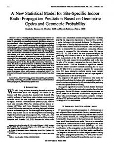
Fig. 1. Cross section of typical three and four conductor cables found in residential PL networks. The table lists typical parameters for the differential and pair-modes that arise in our MTL modeling.
today, and advantages and drawbacks are pointed out. The recent models found by the authors and based on MTL theory are summarized in Section IV, where several new experimental results that validate the model are also presented and demonstrate the power of signal flow theory for model reduction. Following a bottom-up approach, the circuit level models originating from MTL theory are recast into a more convenient communications channel model reminiscent of the classical twisted-pair analysis in Section V. Concluding remarks are drawn in Section VI. II. WIRING AND GROUNDING PRACTICES AROUND THE WORLD There are three common configurations for delivering power from the local distribution transformer: single-phase, two/splitphase, and three-phase. In a single-phase configuration, a hot and a return (neutral) wire are fed to the premises main panel. Sometimes a separate ground (earth) wire is also added. This configuration is typical of small residential buildings. The twophase configuration is not common in Europe, but is typical in the U.S. in the so called split-phase configuration. In a typical U.S. home, three wires are brought to the premises panel from a center-tapped step-down transformer. 120 V devices with low to moderate power requirements ( 1500 W) are typically connected across one transformer winding or the other. Larger devices (electric stoves, central air conditioning units, electric dryers, etc.) are wired across the entire transformer, receiving 240 V. Three-phase configurations (two hot wires plus one return) are common in Europe, but not in the U.S., and neighboring homes may be served from different phases. The threewire system that the user sees is typically derived from three phase distribution, which uses a four-wire or five-wire system. In the five-wire system, there are three hot wires, one neutral wire, and one grounding wire. Residential power cables are comprised of two or three conductors in addition to the ubiquitous earth ground. These include “hot” (black), “return” (white), safety ground and “runner” (red) wires, all confined by an outer jacket that maintains close conductor spacing. Most common cables are unshielded cables (NEMA type NM). Cross-sectional views of the two most common unshielded residential PL cable types, 2/ground and 3/ground, are shown in Fig. 1 together with some
1306
IEEE JOURNAL ON SELECTED AREAS IN COMMUNICATIONS, VOL. 24, NO. 7, JULY 2006
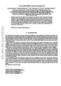
Fig. 2. (a) Typical indoor topology with ground bonding; for details on the topology, see [1, Fig. 7]. (b) Simulated transfer function obtained on the basis of a two-conductor transmission line model. (c) Actual measured transfer function of the topology in (a) (from X to Y).
important cable parameters directly measured using TDR. Note that PL cables differ from traditional twisted-pair cables in that the mutual capacitance of the black and white signal pF/m is significantly smaller than the conductors mutual capacitance between the signal wires and the central or –120 pF/m. ground conductor Tree or star configurations, i.e., a single cable feeds all the wall outlets in a room only, are almost universally used. In Europe, both two-wire (ungrounded) and three-wire (grounded) outlets can be found. Interestingly, if a three-phase supply is used, separate rooms in the same apartment may be on different phases. The U.K. has its exceptions and may use special ring configurations: a single cable runs all the way around part of a house interconnecting all of the wall outlets, and a typical house will have three or four such rings. There are also some cases, especially in old buildings, where only two wires run around the house (neutral and ground share the same wire). While the “white” return wires and safety grounds are isolated throughout all distal network branches, many national and international regulatory bodies today mandate that the return (white) and ground cables be connected together or “bonded” (e.g., short) at the service panel via a low resistance shunt [1], [2]. There is substantial mode coupling created by the elec-
, which has been largely ignored in pretrical path through vious models of indoor PL links. We have conducted experiments which show that ground bonding has a dramatic effect on the PL channel transfer function. Early experiments were reported in a previous publication (see [2, Fig. 5]). We report here another experiment where we considered the topology in Fig. 2(a), which includes ground bonding at the main panel. Fig. 2(b) shows the simulated voltage transfer function from X to Y that the traditional two-wire transmission line model would predict for the topology in Fig. 2(a), i.e., a model that excludes the effects of common grounding practices. As is clearly shown by Fig. 2(b), the actual measured transfer function is very different from the model prediction. Although this experiment clearly demonstrates that bonding creates significant effects that cannot be described by a two-conductor transmission line model that omits the effects of mode coupling, the modeling of grounding practices has always been neglected and it has been taken into account for the first time only recently [1], [2], [10]. As described above, wiring and grounding practices come in many flavors, and this makes modem design much more challenging. However, international harmonization has been underway for the past 25 years, and many regulatory bodies,
GALLI AND BANWELL: A DETERMINISTIC FREQUENCY-DOMAIN MODEL FOR THE INDOOR PL TRANSFER FUNCTION
such as the U.S. National Electric Code (NEC), have revised a harmonized set of practices. In particular, the following practices are now mandatory in most parts of the world. • Typical outlets have three wires: hot, neutral, and ground: GFI protection is also required in many cases. • Classes of appliances are fed by separate overcurrent protected circuits. • Neutral and ground are separate wires within the home, but are bonded at the main panel. Although complex network topologies can indeed exist, the above mentioned regulations greatly simplify the analysis of signal transmission over receptacle circuits by limiting the main effects of mode coupling at the breaker box. III. POWER LINE CHANNEL MODELS Ascertaining the transfer function of the PL channel is a nontrivial task since it depends on several (often unknown) variables: the topology of the network and cable parameters; wiring and grounding practices; and the impedance of the attached appliances. A related problem is how to correlate prominent features of an observed transfer function with physical origins via root cause analysis or dominant path identification. There are basically two main approaches to modeling: time-domain and frequency-domain. A. Time-Domain: The Multipath Model In the time-domain approach, the PL channel is described as if it were predominately affected by multipath effects. The multipath nature of the PL channel arises from the presence of several branches and impedance mismatches that cause multiple reflections. According to this model, the transfer function can be expressed as follows [7]:
(1) where is a complex number that depends on the topology of is the attenuation coefficient which takes into acthe link, count both skin effect and dielectric loss, is the delay assoare the path lengths, and is the ciated with the th path, number of nonnegligible paths. Although this approach has been proven to describe to some extent signal propagation along PL cables, [6]–[8], the multipath model presents several disadvantages. This modeling is based on parameters, including , that can be estimated only after the actual channel transfer function has been measured. Lacking knowledge of port impedances, these models do not readily partition into simpler circuits. Resonant effects due to parasitic capacitances and inductances, and the particular wiring and grounding practices cannot be explicitly included in the model, but only “phenomenologically” observed through the initial measurement. Finally, especially for the indoor case, there is a high computational cost in estimating the delay, amplitude, and phase associated with each of the many paths re(it is a time-domain model, therefore, all the possible flections from the unmatched terminations along the line must be accounted for individually). This is a major drawback for modeling indoor links, where the overall short distances make
1307
Fig. 3. Link configuration for the determination of the paths generated in correspondence of a bridged tap located in A and followed by a discontinuity in C.
it necessary to include many more signal paths because there are many unterminated branches and, moreover, the reflected echoes experience much lower attenuation than in the outdoor case given the shorter length of indoor wires. This last problem has often been underestimated, but constitutes a major drawback for any time-domain model. 1) Generation of Paths Under the Time-Domain Model: The generation of multiple paths in a PL link is due to the fact that each discontinuity or impedance mismatch generates both a reflected and a transmitted signal, so that a part of the signal travels back and forth on the line, bouncing between discontinuities several times before being substantially attenuated enough to be negligible. Obviously, the more the echoes travel on the line the more accentuated will be the multipath effects. Let us now analyze the echoes generated on the PL link shown in Fig. 3 that has a single bridged tap placed along the line at A followed by a second discontinuity at C. Referring to Fig. 3, all discontinuities are described by their complex reflection coefficients, and we assume that transmitter X and receiver Y are matched to the nominal line impedance. As will be shown, even this simple configuration gives rise to numerous echo paths that should be computed individually in a time-domain model. Let us start analyzing the case when only the bridged tap at A is present, and ignore the discontinuity at C; therefore, the . This is a typical distance between A and Y is denoted as configuration analyzed in several published papers [7], [8], [16], [17]. For this configuration, the signal follows a first direct path , and a virtually infinite number of secondary paths arising from the signal bouncing between A and B times, , i.e., , etc. The complex weights , and the path lengths are given by the following expressions:
(2.a)
(2.b) Let us now complicate slightly the situation by adding a generic discontinuity at C following the bridged tap at A (see Fig. 3). The kind of discontinuity at C need not be specified since its behavior is entirely described by the reflection coef. In this case, there are three types of secondary ficient paths arriving at Y: 1) those arising from bounces between A and B; 2) those arising from bounces between A and C;
1308
IEEE JOURNAL ON SELECTED AREAS IN COMMUNICATIONS, VOL. 24, NO. 7, JULY 2006
3) Those arising from bounces between A and B and bounces between A and C. The echo paths and the reflection coefficients pertaining to the above mentioned types of echoes are listed next
(3.a)
(3.b)
(3.c)
(3.d) As shown, by adding just one simple discontinuity the number and type of secondary paths drastically increases. The complexity of individually accounting for all of them can soon get out of hand for typical indoor topologies that can be found in the field and that are characterized by many levels of branching. Moreover, the value of in (1) is unknown because it is not possible to know a priori how many secondary paths are nonnegligible with respect to the direct path. Without a clear lower threshold for , there is a problem of estimating the model order for the multipath model. B. Frequency-Domain: Two-Conductor Transmission Line Models There have been attempts to model the PL channel as a two-conductor transmission line (TL) (see [13]–[16], and references therein) using either transmission or scattering matrices. In those contributions, however, the proposed models led to an incomplete circuit representation that was not capable of fully explaining the physics of signal propagation over PL cables. In particular, these analyses neglected three major points: 1) the presence of a third conductor, which makes the problem one of MTL theory; 2) the effects of particular wiring and grounding practices; and 3) estimation of common mode currents related to electromagnetic compatibility. The major advantage of a frequency-domain model is that its computational complexity is nearly independent of the topology complexity and the number of mismatched branch terminations. In fact, a frequency-domain model contains the composite of all the signals reflected by the discontinuities (multipath) over the measured frequency range, whereas in a time-domain model, it would be necessary to generate all the different paths individually. On the other hand, the major drawback of a frequency-domain approach based on transmission line theory is that everything about the link must be known a priori: the topology, the cable types and their characteristics, and the terminating impedances on every branch: imperfect knowledge about these quantities can impair accuracy of the channel model if they constitute part of the dominant path at a given frequency. The necessity
of this detailed level of knowledge is the price to pay to avoid preliminary measurements, as the multipath model requires. C. Frequency-Domain: Multiconductor Transmission Line Models A more accurate approach to channel modeling based on MTL was originally proposed in [10] for the indoor PL channel, and in [11] and [12] for the outdoor case. This approach can be considered as a natural extension of the two-conductor modeling to include the presence of additional wires. Therefore, this approach has advantages and drawbacks similar to those mentioned in the previous section: complexity nearly independent of topology; and necessity of complete physical knowledge of the link. However, the appealing feature of these models is that they are able to describe the PL channel more accurately than the models that ignore the presence of the ground wire. Building on a successful model for signal propagation in multipair category 5 UTP links utilizing MTL modal decomposition [18], the approach first proposed in [10], and further developed in [1] and [2], is the only available work that takes into account important grounding practices imposed by many regulatory bodies. An important result reported in [1] and [2] is that it is indeed possible to compute a priori and in a deterministic fashion the transfer function of both grounded and ungrounded PL links by using transmission matrices only. This result is due to the fact that the circuit models for the two dominant propagating modes1 along the wires are coupled by a modal transformer at the bonding point, and this coupling is amenable to transmission matrix representation, as well as the two circuit models. As a consequence, it is then possible to model the indoor PL channel in terms of cascaded conventional two-port networks (2PNs) strongly coupled through a modal transformer. Therefore, once the equivalent 2PN representation is obtained, it is possible to represent the whole PL link by means of transmission matrices exclusively. This allows us to compute analytically and a priori the transfer function of any indoor PL link, and also allows us to treat with the same formalism both grounded and ungrounded topologies, thus taking into account the most important wiring and grounding practices found in the field. IV. MEASUREMENTS AND MTL MODEL VALIDATION Due to space limitations, only a limited set of experimental results were reported in [1] to validate the MTL analysis. In this section, we report additional expressions for the matrix reflection coefficients that were not reported in [1, Sec. III.A], and a new set of experimental results carried out to validate the proposed MTL analysis. A. Basic Relationships of Reflection Coefficients Let the voltages (currents) on the three PL wires be , , and , respectively. A three-conductor cable supports six propagating modes (TEM approximation), three spatial modes (differential, pair and common modes) each for two directions of propagation. Let 1The first circuit accounts for differential-mode propagation, while the second circuit (labeled as the “companion model”) accounts for the excitation and propagation of the pair-mode, which is the second dominant mode and arises prominently with certain grounding practices.
GALLI AND BANWELL: A DETERMINISTIC FREQUENCY-DOMAIN MODEL FOR THE INDOOR PL TRANSFER FUNCTION
1309
Fig. 4. Physical model used in our experiments composed of a TDR head driving two sections of 14/2 NM cable connected in series. Programmable shunt impedances are placed at the cable’s junction.
represent the differential, pair-mode and common-mode currents, respectively, for waves propagating in a forward direction.2 The corresponding propagating voltages and are reof characteristic lated to these currents by a diagonal matrix impedances
for this example is given ground. The conductance matrix in [1, eq. (16)] and can be easily derived by visual inspection , , and of Fig. 4, where the location of resistances is indicated. The differential shunt and bonding provide two distinct cases of interest. Let us consider again the case where the excitation consists of a purely differential incident . wave is present, substitution When only the differential shunt with into (6) gives the following of relationships:
(4) (7.a) Following the developments in [1, Sec. III], it is easy to find that of a semi-infithe matrix reflection coefficient nite cable excited by a purely differential incident wave and terminated in an arbitrary linear network described by , assumes the following form: (5) and are defined in [1, eqs. (3) where the modal matrices and (4)]. Similarly, a cable interrupted by a shunt conductance between the three conductors and earth return can be described by a termination having conductance matrix . Substitution of into (5) yields
(7.b) Normal bonding is modeled by , in which case the differential-mode reflection coefficient obtained into (6) gives by substituting
(8.a)
(6) In the present work, we have examined mode coupling proplaced between hot and reduced by a differential shunt , and the fault turn wire, bonding through a shunt resistance condition created by a shunt resistance between hot and 2Subscripts
1 and 2 denote the sections of the cable before and after a discontinuity, respectively. Superscripts and denote forward and backward traveling waves. Finally, bold letters denote vectors and matrices.
(8.b)
(8.c) (8.d)
1310
IEEE JOURNAL ON SELECTED AREAS IN COMMUNICATIONS, VOL. 24, NO. 7, JULY 2006
The bonding impedance creates a negative differential-mode voltage reflection, while the pair-mode signal is ultimately not inverted since the ground wire potential is pulled “down.” The fault condition with black wire connected to ground yields
(9.a)
(9.b)
(9.c)
Fig. 5. Measured TDR traces of differential and pair-mode excitation for three different shunt types: differential, bonding, and fault.
and . The terminal voltages associated with the excitation signal satisfy
(9.d) These expressions manifest fundamental consequences of mode transformation and will be exploited for the experimental verification.
(11.a)
B. Experimental Validation Using Signal Flow Analysis
(11.b)
A physical model was constructed for validating the MTL cable model and evaluating the effects of simple cable discontinuities found in PL networks. This is shown in Fig. 4 and consists of a differential TDR head driving two 7.6 m sections of 14/2 NM cable connected in series. At the cable junction, the wires are shunted by three programmable resistors: a differenis placed between hot and return wire, a bonding tial shunt is placed between return and ground wire, and resistance resistance which emulates a fault condition is placed between hot and ground. The TDR head includes a difference amplifier and a differential pulse generator having a differential V and single-ended output open circuit voltage impedances . The ground wire is terminated at an . The end cable is oscilloscope with input resistance . differentially terminated by resistor For a semi-infinite cable driven by a voltage source through an impedance , the conductor voltages and currents . Assuming satisfy the boundary condition , the modal voltages a quiescent initial condition with in this situation satisfy
(10) is matched to the cable When the source impedance impedance, i.e., , one observes: and . is diagonal with elements For the circuit in Fig. 4, matrix , and disposed along the main diagonal, respectively,
The second term in (11.a) containing is generally small (80 mV compared 9600 mV), and consecompared with provides a good estimate for . Parameter can quently, using (11.b) since overall be deduced from the measured they exhibit a weak dependence on uncertainty in the estimated . value of TDR measurements were performed with different values of test impedances. Incident and reflected waves from the shunts could be resolved using an excitation pulse of 30 ns duration. Typical monitored waveforms are shown in Fig. 5 for the three cases with all shunts open (top: excitation/imbalance), (middle: differential), and (bottom: bonding), or (bottom: fault). In the absence of shunt-induced perturbations, the differential signal (top: excitation) shows a clean response. Using (11.a), corresponds the differential signal amplitude to . The measured pair-mode signal (top: imbalance) corresponding ground wire excitation reveals complex structure consistent with spatial variation in . The amplitude suggests assuming a nominal value of in (11.b). While (8.a) and (9.a) afford a complete solution of (6), it should be safe to neglect the efsince is small compared with fects of . The remaining waveforms in Fig. 5 show reflections created by the shunts. The incident wave is not affected by the shunts and was suppressed by subtracting the respective unperturbed waveform, creating the initial flat segments. Application of a differential shunt produces an inverted differential wave
GALLI AND BANWELL: A DETERMINISTIC FREQUENCY-DOMAIN MODEL FOR THE INDOOR PL TRANSFER FUNCTION
1311
Fig. 6. Signal flow diagram applicable to dominant path analysis and TDR measurements that permits simple parameter extraction without de-embedding or explicit deconvolution of multiple mode conversions.
(middle) with slight high-frequency roll-off evident. The corresponding pair-mode voltage in this case represents differential-to-pair mode-conversion of the reflected differential wave at the TDR head. The bonding and fault conditions both produce inverted differential reflections: 1.49 V for the bonding, and 1.77 V for the fault. For comparison, (8.b) predicts an amplitude of 1.51 V for the bonding, although (9.b) predicts an amplitude of 2.62 V for the fault. In the bottom traces, the pair-mode voltages induced by bonding and fault conditions have different polarities and slightly different amplitudes as expected, although the voltage values predicted by (8.c) and (9.c) are approximately 30% higher. The apparent discrepancy is attributed to additional mode conversion of the reflected waves at the TDR head. As pointed out in [1, Sec. III], the reciprocal of all the scalar reflection coefficients found exhibit a simple linear dependence on the independent parameters , , and (see [1, eqs. (18.a)–(18.c)]). This suggests that the response to variations in or can be used to extract cable parameters by simple linear regression. However, the qualitative results in Fig. 5 reveal that the desired signals are significantly contaminated by multiple occurrences of mode coupling. Signal flow theory [20] can be used to extract some of the desired information provided by impedance perturbation experiments without resorting to explicit deconvolution. Many elements in a power distribution network appear as shunts across the channel. Fig. 6 presents a signal flow diagram applicable to a wide range of measurements with input stimulus X, a test port U, and measured response Y. For TDR measurements, X and Y correspond to signals at same physical port. Input signal X creates an internal voltage AX. The as a circuit beyond test port V appears to shunt resistance . voltage source AX in series with an internal impedance includes all feedback loops, including multiple Impedance reflections. A current flows through the . If X and I are treated as independent signals, the obshunt ; served output signal Y can be represented as consequently, the overall transfer function is given by
(12)
Fig. 7. SPICE simulation results confirming the measurements in Fig. 5.
and where . It can be seen that is contained within a dominant and . For the path when TDR measurements shown in Fig. 5, , and baseline for subtraction using the response gives
(13) can be extracted from a linear Equation (13) shows that plot of versus as the ratio of the intercept and slope. Equations (7.b) and (8.b) represent special cases of . For a differential shunt, the intercept(13) for which , while measurements of slope ratio gives a bonding or fault shunt yields or , respectively. Simultaneous comparison of results for bonding and fault models gives two useful relationships
(14.a) (14.b) which enable simple extraction of and from measurements, respectively, without resorting to complicated de-embedding. A SPICE model [19] was constructed for the circuit in Fig. 4 using the cable model described by [1, eqs. (3) and (4)] with the parameters extracted from the measurements reported in [1, Fig. 5]. Fig. 7 shows SPICE simulation results for the shunt conditions used in preparing Fig. 5. Except for reflections caused by spatial variation noted previously, the waveforms produced by the SPICE simulation in Fig. 7 match the amplitudes shown in
1312
IEEE JOURNAL ON SELECTED AREAS IN COMMUNICATIONS, VOL. 24, NO. 7, JULY 2006
Fig. 5 within 5%. Taken together, this set of experiments demonstrated that two dominant modes are present and mode coupling is associated with impedance conversion. They validate the model by arriving at consistent results. Signal flow theory was introduced to reconcile discrepancies between the experimental results here reported and the relationships reported in [1, eqs. (18.a)–(18.c)], which we attribute to multiple occurrences of mode coupling.
A general result of TL theory is that every uniform TL can be modeled as a 2PN, thus allowing us to replace a distributed parameter circuit with a single lumped network. In TL theory, a common way to represent a 2PN is to use the transmission matrix , also known as the ABCD matrix. The relationship between current and voltage (in the frequency-domain) at the two ports of a 2PN is given by the following expression3:
(15)
V. DETERMINISTIC MODELING BASED ON TWO-PORT NETWORKS (2PNS) The circuit models described in [1] permits accurate analysis using SPICE circuit simulation. The full SPICE model depends on primary parameters such as characteristic impedance and propagation delay that exhibit small variations from cable to cable and can be considered known (see Fig. 1), and on secondorder parameters such as the cable uniformity parameters and defined in [1, eqs. (3) and (4)]. While the second-order parameters have a measurable effect on differential signal propagation, they primarily affect mode excitation relevant to electromagnetic compatibility. Few papers address the challenge of physical models for PL electromagnetic compatibility (see, for example, [21]). Parameter describes shielding by the ground conductor. In since simulating the full model in SPICE, we assumed this parameter primarily affects EMC performance (emissions and susceptibility), and we are here focusing on the channel transfer function. Parameter describes pair-mode asymmetry between the hot and return wires, with respect to the ground conductor. The average value of parameter was estimated to be 0.23 on the basis of measurements performed over three wire cables (see Section IV-B here, and [1, Sec. III-B]). The closeness of the measured TDR traces and the simulated ones (compare Figs. 5 and 7), justify the correctness of the above considerations so that there is actually no need of having full knowledge of the geometry and relative position of all the cables along the PL link in computing the channel response. However, this may not be valid for EMC analysis (see, for example, [21]). As described in [2], we crossed several layers of abstraction starting from the lower level circuit models to arrive finally to the model based on 2PNs and ABCD matrices. In order to disentangle ourselves from the necessity of the preliminary measurement of , we assumed the existence of symmetry between hot and return with respect to the ground cable along the whole PL link. In practice, cables do not maintain such symmetry and they may be twisted in some locations or even flip position with respect to each other. An MTL approach is probably still able to describe this by taking into consideration the interaction between differential- and pair-modes, but the level of precise knowledge of the geometry of the PL cables across the whole PL link becomes an unbearable burden. Although the symmetry assumption may not be true in practice, the results in [2] have shown that the simulated transfer function is very close to the measured one. Therefore, the 2PN modeling given in [2], and generalized in this section to model a generic PL link, does not require preliminary measurements and this does not reflect into poor accuracy in predicting the transfer function.
where the ABCD coefficients are generally complex functions of frequency, and fully characterize the electrical properties of a 2PN. The ABCD parameters allow us to calculate two important quantities: the transfer function as the ratio of the voltage on the load to the source voltage, and the input impedance of the network [9]
(16) In the case of a two-conductor TL, the ABCD coefficients and the corresponding transmission matrix take on the following expression:
(17) are the length, the propagation constant, and where , , and the characteristic impedance of the cable, respectively. These quantities can be either estimated from measurements as done in [1] and [13], or computed using analytical tools [11], [12], and [16]. In general, a TL is made of several sections and each section may consist of different cable segments of different lengths. An important property of the transmission matrix is that it easily allows us to handle tandem connections of 2PNs since the overall ABCD matrix of the end-to-end circuit is obtained by multiplying the ABCD matrices of the single portions of the netof the work. Therefore, the overall transmission matrix sections connecting nodes end-to-end circuit consisting of X and Y is given by the following relationship:
(18) where
is the transmission matrix of the th section.
of notation, hereinafter the explicit dependency on frequency of A, = 1; 2) has been omitted. For more details on 2PN modeling see [2] and references therein. 3For ease
B , C , D , Z , , Z , Z , V , and I (x
GALLI AND BANWELL: A DETERMINISTIC FREQUENCY-DOMAIN MODEL FOR THE INDOOR PL TRANSFER FUNCTION
1313
Fig. 10. The PL link in Fig. 8(a) for the grounded case showing the presence of the companion model representing the effects of bonding in the main panel.
Fig. 8. (a) Modems in X and Y are located at the opposite sides of the service panel. (b) Modems in X and Y are located on the same side of the service panel.
bridged tap located at the main panel. This case will be addressed in detail in the next section. A. Modeling Grounded and Bonded Indoor Topologies Let us consider a generic topology of a PL link between two modems located at nodes X and Y. We have two possible cases: X and Y are on the opposite sides of the main panel breaker box, as depicted in Fig. 8(a); X and Y are on the same side with respect to the main panel breaker box, as depicted in Fig. 8(b). 1) First Case: Modems on Different Sides of the Main Panel: Let us start with the case in Fig. 8(a), and its equivalent representation shown in Fig. 10. The overall transmission matrix (18) for the channel from node X to Y is
Fig. 9. The PL link in Fig. 8(a) for the ungrounded case.
The appealing feature of the MTL approach proposed in [1] is that transmission matrices are able to describe both the case where the indoor wiring consists of only two wires (single or split phase with ungrounded outlets; return and ground sharing common wire), and the case where three wires are present (hot, return, and ground) with bonding at the main panel as mandated by the U.S. NEC. In the first (ungrounded) case, every transmission matrix represents a section of the two-wire topology or a common series or shunt impedance along the wires; this case does not require the companion circuit model and represents the conventional case also addressed in [13]–[16]. In this case, the overall transmission matrix of the PL link is as follows (see the corresponding Fig. 9):
(19) In the second (grounded) case, one of the transmission matrices in (18) models the bonding at the main panel, as proposed in [1] and [2]. In particular, the companion model needs to be taken into account and the topology of the link equivalent to Fig. 8(a) when grounding is present is shown in Fig. 10. As Fig. 10 clearly shows, the companion model appears as a
(20) The transmission matrix representing the mains feed into the home wiring is the matrix representing a bridged tap onto the main cable (hot return), terminated on impedance , which represents the (usually low) impedance seen looking into the low-voltage transformer
(21) , , , and are the ABCD coefficients reprewhere senting the mains feed cable. The panel where ground bonding is located can be expressed as a shunt impedance across hot and return, and its transmission matrix has the following expression:
(22) is the input impedance seen where the impedance looking into the 2:1 modal transformer followed by the companion circuit model describing pair-mode propagation (see
1314
IEEE JOURNAL ON SELECTED AREAS IN COMMUNICATIONS, VOL. 24, NO. 7, JULY 2006
terest, we can now write the expression of the transfer function (16) of the PL link between X and Y
(25)
Fig. 11. Structure of the topology of the companion model describing pair-mode excitation and propagation due to the bonding. The input impedance looking into the networks are shown.
[2, Sec. III]). The companion circuit model is easy to devise since it has the same topology as the actual PL link (differential circuit model), with the exception of the feed line entering the low-voltage transformer which does not have a pair-mode element since the return provides grounding [2]. Therefore, the is given by the input impedance of the impedance network depicted in Fig. 11 that is represented by the following “companion circuit” transmission matrix:
where is the output impedance of the modem in X and is the input impedance of the modem in Y. Note that, as proved in [2], if , i.e., the transfer function is symmetric. 2) Second Case: Modems on Same Side of the Main Panel: Let us now turn to the case in Fig. 8(b). In this case, everything to the right of the receiver Y must be treated as a bridged tap just before node Y. Therefore, the overall transmission matrix (18) for the channel from node X to Y is now
(26) where the transmission matrix
has the following form:
(27) represents the input impedance of the circuit on the and right of Y, as shown in Fig. 8(b). This impedance can be calculated as follows:
(28)
(23.a)
is the load impedance attached to . The ABCD cowhere efficients in the previous equation can be computed as follows:
(23.b)
is the transmission matrix of the modal transwhere former and has the expression in Fig. 11 for a generic value of bonding resistance (see also [2, eq. (15)]). is the bonding resistance and , are the input impedances of the two circuits depicted in Fig. 11. In (23.a) and (23.b), we have considered that either the left or the right circuits in Fig. 11 can be seen as a bridged tap over the other. Finally, the input impedance is as follows:
(24) where is the load impedance attached to either [if the left circuit is the bridged tap, and (23.a) is used], or to [if the right circuit is the bridged tap, and (23.b) is used]. After calculating the ABCD parameters of in (20) at all frequencies of in-
(29)
VI. CONCLUSION A novel PL transfer function modeling approach was recently proposed and experimentally validated [1], [2], [9], [10]. This approach, based on MTL theory and modal decomposition, allows us to treat with the same formalism both grounded and ungrounded topologies and, therefore, to take into account the most important wiring and grounding practices that can be found in the field. Several layers of abstraction must be crossed, starting from complex circuit models derived on the basis of MTL theory, and finally arriving at an equivalent model expressed in terms of cascaded 2PNs. This approach, allowing us to make the PL channel amenable of description via transmission matrices, is reminiscent of the classical modeling
GALLI AND BANWELL: A DETERMINISTIC FREQUENCY-DOMAIN MODEL FOR THE INDOOR PL TRANSFER FUNCTION
of twisted pairs and is more useful from a communications point of view than the MTL-based circuit models. As a consequence, we can now compute deterministically and a priori the transfer function of any indoor PL link by including wiring and grounding practices. The proposed deterministic model can be used in conjunction with the definition of a set of commonly agreed upon PL topologies to be used for channel standardization. In fact, the major drawback of transmission line theory modeling, i.e., the necessity of the knowledge of the whole topology, becomes a moot point since all this information would be available from the moment the ensemble of standardized topologies is set. We also believe that the same methodology could be adopted for characterizing the case of in-vehicle wiring. In this case, wiring and practices are well documented during the design phase so that all the information required by transmission line modeling is easily available [22]. The availability of an accurate channel model allows us to move toward the definition of standardized channel models. Now that standardization activities for PL communications have started within IEEE and ETSI, it is necessary to work toward the definition of both a commonly agreed upon channel model and a set of standardized transfer functions. The next step is, therefore, to create a set of topologies (and practices) that can be considered as representative of the majority of topologies that can be found in the field. In fact, given the wide variability of topologies and practices, it is necessary to devise a set of topologies with their associated transfer functions so that coding and modulation schemes can be tested against them and compared objectively and with repeatability of results, something that only a commonly agreed upon model will allow. In addition, the proposed deterministic model can also be the basis for the generation of a set of statistically relevant random transfer functions following, for example, the approach proposed in [14]. While several groups are pursuing methods to deduce relevant statistical behavior from ensembles of physical models, we believe that our approach allows one to preserve inherent determinism as much as possible, including correlations between differential and companion (pair-mode) models. It is likely that several PLC elements, such as the service feed or the ground bonding at the main panel, will be associated with regular features of the transfer function: the ability to correlate these elements with their effect on the transfer function will be helpful to generating good statistical models. As a final remark, we wish to point out that the results found by the authors indicate that, if properly modeled, the PL channel transfer function exhibits more determinism than commonly believed. This determinism should be exploited for robust modem design and system optimization. For example, the symmetry of the PL channel (proven and experimentally validated in [2] and [9]) opens the door to information theoretic considerations on optimal transmission when the channel is known at the transmitter. For example, treating known intersymbol interference (ISI) as interference known as the transmitter allows us to use more effectively precoding schemes such as Tomlinson–Harashima or, more in general, dirty paper coding. Moreover, as reported in [2], it is possible to isolate reflections and resonant modes on the basis of specific features of the PL topology. This property of superposition of resonant
1315
modes allows us to assess more effectively the similarities (correlation) between the PL transfer functions before and after devices are plugged in or out, and this knowledge can be embedded into the adaptive equalizer of a PL modem.
REFERENCES [1] T. Banwell and S. Galli, “A novel approach to accurate modeling of the indoor power line channel—Part I: Circuit analysis and companion model,” IEEE Trans. Power Del., vol. 20, no. 2, pp. 655–663, Apr. 2005. [2] S. Galli and T. Banwell, “A novel approach to accurate modeling of the indoor power line channel—Part II: Transfer function and channel properties,” IEEE Trans. Power Del., vol. 20, no. 3, pp. 1869–1878, Jul. 2005. [3] S. Galli, A. Scaglione, and K. Dostert, “Broadband is power: Internet access through the power line network,” IEEE Commun. Mag., vol. 31, no. 5, pp. 82–83, May 2003, Guest Editorial. [4] H. Latchman and L. Yonge, “Power line local area networking,” IEEE Commun. Mag., vol. 31, no. 4, pp. 32–33, Apr. 2003, Guest Editorial. [5] E. Biglieri, “Coding and modulation for a horrible channel,” IEEE Commun. Mag., vol. 31, no. 5, pp. 92–98, May 2003. [6] H. Philipps, “Modeling of power line communications channels,” in Proc. IEEE Int. Symp. Power Line Commun. Appl., Lancaster, U.K., Apr. 1999, pp. 483–485. [7] M. Zimmermann and K. Dostert, “A multipath model for the power line channel,” IEEE Trans. Commun., vol. 50, no. 4, pp. 553–559, Apr. 2002. [8] J. Barnes, “A physical multi-path model for power distribution network propagation,” in Proc. IEEE Int. Symp. Power Line Commun. Appl., Tokyo, Mar. 1998, pp. 76–89. [9] T. Banwell and S. Galli, “On the symmetry of the power line channel,” in Proc. IEEE Int. Conf. Power Line Commun. Appl., Malmo, Sweden, Apr. 4–6, 2001. [10] ——, “A new approach to the modeling of the transfer function of the power line channel,” in Proc. IEEE Int. Conf. Power Line Commun. Appl., Malmo, Sweden, Apr. 4–6, 2001. [11] T. Sartenaer and P. Delogne, “Power cables modeling for broadband communications,” in Proc. IEEE Int. Conf. Power Line Commun. Appl., Malmo, Sweden, Apr. 4–6, 2001. [12] T. Calliacoudas and F. Issa, “Multiconductor transmission lines and cables solver, an efficient simulation tool for PLC networks development,” in Proc. IEEE Int. Conf. Power Line Commun. Appl., Athens, Greece, Mar. 27–29, 2002. [13] T. Esmailian, F. R. Kschischang, and P. G. Gulak, “In in-building power line channel simulator,” in Proc. IEEE Int. Conf. Power Line Commun. Appl., Athens, Greece, Mar. 27–29, 2002. [14] ——, “In-building power lines as high-speed communication channels: Channel characterization and a test-channel ensemble,” Int. J. Commun. Syst., vol. 16, pp. 381–400, 2003. [15] O. G. Hooijen, “On the relation between network-topology and power line signal attenuation,” in Proc. IEEE Int. Conf. Power Line Commun. Appl., Tokyo, Japan, Mar. 24–26, 1998, pp. 45–56. [16] H. Meng, S. Chen, Y. L. Guan, C. L. Law, P. L. So, E. Gunawan, and T. Lie, “Modeling of transfer characteristics for the broadband power line communication channel,” IEEE Trans. Power Del., vol. 19, no. 3, pp. 1057–1064, Jul. 2004. [17] H. He, S. Cheng, Y. Zhang, and J. Nguimbis, “Analysis of reflection of signal transmitted in low-voltage powerline with complex wavelet,” IEEE Trans. Power Del., vol. 19, no. 1, pp. 86–91, Jan. 2004. [18] C. R. Paul, Analysis of Multiconductor Lines. New York: Wiley, 1994. [19] ——, “A SPICE model for multiconductor transmission lines excited by an incident electromagnetic field,” IEEE Trans. Electromagn. Compat., vol. 36, no. 4, pp. 342–354, Nov. 1994. [20] J. Choma, Jr., “Signal flow analysis of feedback circuits,” IEEE Trans. Circuits Syst., vol. 37, pp. 455–463, Apr. 1990. [21] T. Banwell, “Accurate indoor residential PLC model suitable for channel and EMC estimation,” in Proc. IEEE Workshop Signal Process. Advances Wireless Commun., New York, Jun. 6–8, 2005, pp. 985–990. [22] S. Galli, T. Banwell, and D. Waring, “Power line based LAN on board the NASA space shuttle,” in IEEE Veh. Technol. Conf., Milan, Italy, May 17–19, 2004, pp. 970–974.
1316
IEEE JOURNAL ON SELECTED AREAS IN COMMUNICATIONS, VOL. 24, NO. 7, JULY 2006
Stefano Galli (S’95–M’98–SM’05) received the M.S. and Ph.D. degrees in electrical engineering from the University of Rome “La Sapienza,” Rome, Italy, in 1994 and 1998, respectively. After completing the Ph.D. degree, he continued as a Teaching Assistant in Signal Theory at the Info-Com Department, University of Rome. In October 1998, he joined Bellcore (now Telcordia Technologies), Piscataway, NJ, in the Broadband Networking Research Department, where he is now a Senior Scientist. He is a reviewer for several IEEE journals and conferences, has published around 80 papers, and holds several international issued and pending patents. His main research efforts are devoted to various aspects of xDSL systems, wireless/wired home networks, personal wireless communications, power line communications, and optical CDMA. His research interests also include detection and estimation, communications theory, and signal processing. Dr. Galli is currently serving as Chair of the IEEE Communications Society Technical Committee on “Power Line Communications.” He also served as a Co-Guest Editor for the Feature Topic “Broadband is Power: Internet Access Through the Power Line Network” in the IEEE Communications Magazine, May 2003. He often serves as Technical Program Committee member in IEEE conferences, has served as the General Co-Chair of the IEEE Workshop on Signal Processing Advances in Wireless Communications (SPAWC’05), and is currently serving as the Vice-Chair of the General Symposium of the IEEE International Conference on Communications (ICC’06), and as the Co-Chair of the General Symposium of the IEEE Global Communications Conference (Globecom’06). He is also serving as an Associate Editor for the IEEE SIGNAL PPROCESSING LETTERS and Area Editor for Signal Processing for Communications.
Thomas C. Banwell (M’90) received the B.S. degree in chemical physics from Harvey Mudd College, Claremont, CA, in 1978, the M.S. degree in electrical engineering and the Ph.D. degree in applied physics from the California Institute of Technology, Pasadena, in 1980 and 1986, respectively, and the MD degree from UMDNJ-New Jersey Medical School, Newark, in 1997, and did an Internship in Internal Medicine. He has been a member of Technical Staff at Telcordia Technologies, Morristown, NJ, since 1986, pursuing problems related to performance limitations in low power/high-speed electronic circuits that arise in public telecommunications network access and data processing applications and variable bit rate optical transmission systems. He has authored or coauthored more than 70 technical papers and has seven patents. His interests in circuit theory have expanded to include modeling physiological processes such as uterine contraction.