A Distributed, Heterogeneous Control System for the ALICE TPC Electronics J. Alme, M. Richter, D. Larsen, D. R¨ohrich, K. Ullaland Department of Physics and Technology, University of Bergen, Norway
[email protected],
[email protected]
K. Røed Faculty of Engineering, Bergen University College, Norway
S. Bablok, R. Keidel, Ch. Kofler Center for Technology Transfer and Telecommunications, University of Applied Science Worms, Germany
T. Krawutschke Institute of Communication Engineering, University of Applied Sciences Cologne, Germany
T. Alt, D. Gottschalk, H. H¨obbel, V. Kiworra, V. Lindenstruth, M. R. Stockmeier Kirchhoff Institute of Physics, University of Heidelberg, Germany
U. Frankenfeld GSI, Gesellschaft f¨ur Schwerionenforschung, Darmstadt, Germany
R. Campagnolo, C. Engster, C. Gonzalez Gutierrez, A. Junique, B. Mota, L. Musa CERN, European Organization for Nuclear Research, Geneva, Switzerland
Abstract The ALICE detector is a dedicated heavy-ion detector currently built at the Large Hadron Collider (LHC) at CERN. The detector consists of several sub-detectors each of them forming a highly complex device. The Detector Control System (DCS) covers the task of controlling, configuring and monitoring of the detector system. Since the experiment will be running in a radiation environment, fault tolerance, error correction and system stability in general are major concerns. A system consisting of independently running layers has been designed, the functionality layers are running on a large number of nodes and sub-nodes. An autonomous single-board computer, the DCS board, has been developed which allows one to run the operating system Linux in an embedded environment and to perform tasks related to the hardware devices. Further custom hardware devices have been developed covering specific tasks and serving as sub-nodes. These devices together with standard computers in higher control layers form a distributed control system. This article will focus on the concept and architecture of the DCS for the Front-end electronics of the TimeProjection Chamber (TPC) and present results and experiences from system integration tests.
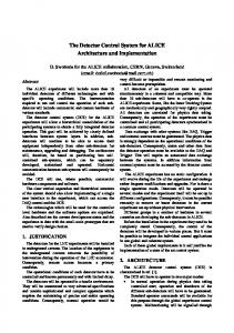
Figure 1. The ALICE detector
1 Introduction ALICE is one of four experiments at the LHC at CERN. It is designed to investigate collisions of lead nuclei and protons which are accelerated by the LHC. The ALICE experiment is outlined in [1]. LHC and the ALICE detector are currently under development and are scheduled to be commissioned in 2007. To be able to differentiate all the particles resulting from the freeze-out of a nuclear collision, huge detectors need to
Proceedings of the 2005 International Conference on Parallel Processing Workshops (ICPPW’05)
1530-2016/05 $20.00 © 2005 IEEE
be built. Figure 1 shows an overview of the ALICE detector. Surrounding the detector is a huge magnet, and inside this magnet many of the sub-detectors are found. The main sub-detectors of the central arm are the ITS (Inner Tracking System), TPC (Time Projection Chamber), TRD (Transition Radiation Detector), TOF (Time of Flight), PHOS (PHOton Spectrometer) and HMPID (High Momentum Particle Identification Detector). In addition to this there are different smaller detector systems, e.g. for trigging. All the mentioned sub-detectors have configurable variables all the way down to the hardware level, and the DCS has to continuously measure parameters. The TPC detector itself has a configuration consisting of approximately 4500 Front-End Cards communicating with 216 Readout Control Units. In each Front-End Card there are 128 channels that provide data and these channels must be individually configured. Adding this together gives close to 600 000 channels that must be individually configured in the TPC detector alone. The ALICE detector works in a radiation environment. In such an environment errors in the Front-end electronics will occur, that may lead to a malfunctioning of the system. It is of high importance to detect and repair these errors as soon as possible, to prevent permanent damage and errors in the data-stream. Physical shielding of the sensitive parts cannot be implemented, as this will effect the particle measurements. The limited accessibility of the ALICE detector is also an important aspect. Hardware errors that may have occurred cannot be repaired without dismantling the whole detector. This article will focus on one of the embedded computer systems used for controlling the TPC, PHOS and TRD detector Front-end electronics. The setup of the TPC and PHOS control systems are practically identical, while the TRD has a slightly different setup. The control system for the TPC detector will be investigated in-depth, while experiences from the TRD detector and the PHOS detector will also be discussed because of the similarities.
tem (DCS). Detailed information on the components and architecture can be found in [2]. The various components not concerning the TPC Front-end electronics will not be investigated further. Supervisory Layer
PCs with a Commercial Controlling Software
Control Layer
PCs with Communication Software
Field Layer
Embedded Computer
Embedded Computer
Embedded Computer
Embedded Computer
sub-node
sub-node
sub-node
sub-node
TPC Front-end electronics
TPC Front-end electronics
TPC Front-end electronics
TPC Front-end electronics
Figure 2. A sketch of the Detector Control System in ALICE for the TPC sub-detector. A sketch of the DCS for the TPC Front-end electronics is given in figure 2 showing the principles of the architectural layout. It is a distributed computer system that is divided into three layers, Supervisory Layer, Control Layer and Field Layer. The Supervisory Layer is the top-level with the operator’s user-interface. The Control Layer is a communication layer, and the Field Layer is where the different nodes are found. All the nodes in the system work in parallel, feeding the operator with useful information concerning the status of the system, or responding to commands given at the top-level. It is important to notice that the control system is detached from the data-flow. The data is transported from the Front-end electronics to Data Acquisition (DAQ) through an optical link. The main task of the control system is to avoid occurring system errors interrupting the data-flow.
3 The Distributed Control System 3.1 Tasks of the Detector Control System
2 Overall Architecture To be able to handle such a huge and complex system, a sophisticated control system is needed. The system needs to be able to run under harsh conditions, in which it has to work from the day it is installed. Because of the limited accessibility, it also needs to be easily reconfigurable and it must be possible to detect error conditions at an early stage and notify the operator. It also needs to be able to automatically act upon certain severe error conditions in order to prevent permanent damage to the hardware. Furthermore the cooling system, the ventilation system, the magnetic fields, etc have to be controlled. In general for the ALICE project these tasks are covered by the Detector Control Sys-
The DCS investigated in this article is responsible for configuring, monitoring and controlling the Front-end electronics of sub-detector systems. The control system is designed to automatically act upon different conditions that may occur in the equipment, e.g. shutting down a FrontEnd Card in the TPC system, if the voltage level exceeds a given threshold. The configuration task includes uploading configuration data to certain FPGAs on the Front-End Cards. This data is stored in the Configuration Database and includes physical location of the equipment, hardware addresses and different operational modes. This information covers both hardware and software. The tasks of the control system will be distributed over many PCs and embedded computing devices forming a het-
Proceedings of the 2005 International Conference on Parallel Processing Workshops (ICPPW’05)
1530-2016/05 $20.00 © 2005 IEEE
erogeneous system. This ensures a scalable design that easily can be adapted in case of changes in the complete system. Such architecture is also needed because of the scale of the control system, and to allow independent operation of the different parts involved.
board. Specialized tasks which are adapted to the underlying hardware run on the sub-nodes while the more complex tasks are running on the node itself. The DCS board contains components that make it capable to run a light-weight version of Linux. More details are given in chapter 4
3.2 Hardware architecture The hardware architecture is described by three layers. From top to bottom this is (see figure 2): The Supervisory Layer The Supervisory Layer consists of a number of PCs and provides user interfaces to the operator. It communicates with the Configuration Database and connects to disk servers. It also communicates with external systems for the LHC itself. The Control Layer The Supervisory Layer communicates with the Control Layer mainly through a LAN network. This layer consists of PCs, PLCs (Programmable Logic Cells) and PLC like devices. The Control Layer collects and processes information from the Field Level, as well as sending commands and information from the Supervisory Layer to the Field Layer. The Field Layer The Field Layer consists of all field-devices, sensors, actuators and so on. The DCS board with its sub-nodes is located in this layer. Sharing of devices between different sub-systems is avoided whenever it’s possible, so that independent operation is ensured. This is also an important issue in development and commissioning of the system, so that each subsystem can be debugged and tested separately from other parts of the system. This technique is called partitioning and is a widely used feature in the design of ALICE.
3.3 Software architecture The three functional layers of the DCS are represented also in the software architecture. This will be discussed in chapter 5.
3.4 The TPC Front-end electronics sub-system The TPC and PHOS detectors use a specific hardware device, the Readout Control Unit (RCU), to control a set of Front-End Cards (FECs). An RCU consists of the RCU motherboard, from now on referred to as RCU board, and the DCS board embedded computer. The design of the RCU board is based on an FPGA with firmware update possibility and enough space to host other tasks in addition to the readout. The DCS uses the RCU board as a sub-node to the DCS
Figure 3. Read Out Control Unit motherboard v3.0, with a DCS board v1.16, an SIU board and two Front-End Cards attached. Figure 3 shows a picture of a prototype of the system components. In the picture the RCU board is shown with the DCS board and a Source Interface Unit (SIU) board connected. The backplanes can be seen coming out from the back of the card, and two Front-End Cards (FECs) ([3]) are connected to this. Up to 25 FECs can be connected. The event-data is converted from an analog to a digital signal in the FECs, then handled by the RCU and shipped out through an optical link that is sited on the SIU card. The SIU card and the data readout chain are only mentioned for completeness in this article. The DCS boards are independent nodes in a distributed computer system. They are configured to work in parallel, performing sophisticated error-handling and other tasks related to the control system. In addition a DCS board is able to reconfigure its neighboring boards via a JTAG connection in case of malfunction. Registers and memory on the sub-nodes are accessible from the Linux operating system on the DCS board, either directly or indirectly. For that purpose the sub-nodes define memory mapped interfaces which can be accessed from the node via device drivers. More on this topic and an example for the TPC sub-system is given in chapter 5.5. 3.4.1 DCS board embedded computer The DCS board is used in multiple detectors of the ALICE experiment and flexibility has always been a major concern. The core of the system is an Altera EPXA1, containing a 32bit ARM processor with cache and MMU (Memory Man-
Proceedings of the 2005 International Conference on Parallel Processing Workshops (ICPPW’05)
1530-2016/05 $20.00 © 2005 IEEE
agement Unit). Among other features there are 100k gates of PLD (Programmable Logic Device) available. The PLD in combination with the Linux operating system is the chief cause for the flexibility that will be examined in detail in chapter 4. In addition to the FPGA, the board hosts a radiation tolerant 8 MB Flash ROM, 32 MB SDRAM, an Ethernet interface, an ADC (Analog-Digital Converter) for voltage and temperature monitoring, a JTAG connector, as well as dedicated data-lines to the RCU board connector. All these components make the DCS board a custom-made, fullyfunctional computer. 3.4.2 RCU board stability measures The functionality of both the DCS board and the RCU motherboard is based on FPGAs which can experience errors at some point due to the radiation environment. These errors are not of a permanent nature, and will be corrected by reloading the firmware into the configuration memory of the FPGA. The firmware files are stored in radiation tolerant Flash memory. Reloading the configuration and rebooting causes downtime of the specific node. Since the data-path is independent of the status of the DCS board, occasional downtime of the DCS board node is irrelevant. Altera FPGA w/ ARM cpu
Bank 0 Bank 1 Bank 2 Bank 3
FLASH mem w/ Linux
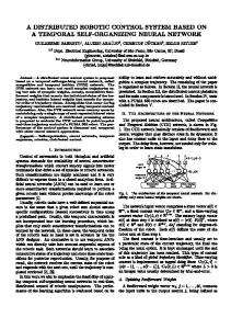
in the Flash memory. This setup makes it possible to remove errors in configuration memory of the FPGA before they affect the behavior of the system. Both the Flash memory and the Configuration Memory of the FPGA is also made available for the DCS board computer, making firmware upgrade possible, or to do more sophisticated error-handling.
4 Linux on DCS board embedded computer The Linux system is one of the main reasons for the flexibility of the DCS-node. It provides a powerful and extendable tool to configure the system to behave as needed in a given situation. The use of device drivers to communicate with different parts of the hardware introduces an abstraction layer which decouples software from hardware. This technique also eases the maintenance of the system. Updated firmware modules and device drivers with new functionality can at any time be inserted in the system. This makes it an organic system that can easily be suited to meet future demands, even if the whole detector system will be physical unavailable. This chapter will focus on the Linux operating system on the DCS boards.
4.1 Armboot After power-up and before startup of the kernel the ARM CPU starts executing at address 0 of the flash memory, at which the bootloader (armboot) is located. The bootloader initiates the boot sequence and fulfills three major duties: Configure the PLD (see chapter 4.3)
DCS-board RCU-board
Xilinx FPGA
Radiation hard CPLD
Bank 0
Copy the kernel command line to memory
Bank 1 Bank 2 Bank 3
Copy the compressed kernel image to memory.
FLASH
Figure 4. Reconfiguration scheme for the Xilinx FPGA on the RCU board.
This simple approach is not satisfying for the FPGA on the RCU board, as it will interrupt the data-flow. To overcome this problem automatic checking and refreshing of the firmware has been implemented. The scheme is sketched in figure 4. It is based on an FPGA which allows one to refresh the firmware without interrupting the operation. In the current system a Xilinx Virtex-II Pro device [4] has been chosen. In addition there are a CPLD (Complex Programmable Logic Device) and a Flash Memory on the RCU motherboard, that both are radiation tolerant. The custom-made design in the CPLD can continuously refresh the configuration memory, or if needed, read back the configuration memory and verify it against the original binary-files stored
Armboot ends itself by handing over control to the kernel image which extracts to main memory.
4.2 Kernel startup and device drivers The first actions the kernel takes after self-extraction are starting the caches, the MMU, initializing the stack and setup of the interrupt descriptor table. These are platform and processor specific setups which are unique for the EPXA1 on the DCS board. Also the paging is prepared with the setup of the global descriptor table and the page table. After this the kernel continues with startup, which is independent of the processor architecture it runs on, except for the device drivers which are initialized at the end. In normal operation the kernel is only activated when an (hardware) interrupt occurs or a system call is issued by a user program. In the terms of abstraction, access to most of the hardware is made available by the device drivers via files residing in the /dev directory. Similar to a regular file on a disk or another file-system, a hardware file can be opened,
Proceedings of the 2005 International Conference on Parallel Processing Workshops (ICPPW’05)
1530-2016/05 $20.00 © 2005 IEEE
closed, read or written. One has to keep in mind that there are rules how to use a specific hardware introduced by the device driver author. The access to a lot of drivers for the hardware on the DCS board, are used as dynamically loadable kernel modules.
4.3 The PLD Much of the hardware presented in the beginning is connected to the PLD of the EPXA1, the central chip. This is in effect a new layer between device driver and hardware. A common application is the protocol machine. Outside the central chip a simple driver/receiver (e.g. a PHY for Ethernet) added and the PLD is configured with the complex hardware necessary for the communication protocol (e.g. the Ethernet Medium Access Controller - MAC). A module that implements memory-mapped communication with other firmware modules on the FPGAs on the DCS and RCU boards is also present. With the Altera tools for the EPXA1 a programming file is created for the device. As stated above the boot-loader armboot loads this configuration into the PLD after system power-up. This has to be done after every power cycle because of the SRAM based technology inside the PLD. This process can also be done later on, when the system is running to reconfigure the PLD for another task or to reload the actual configuration for safety reasons. The cooperation of reconfiguration and loadable kernel modules is the key-feature for the flexibility of the DCS board. With minor changes it is adaptable to several detector sub-systems and other tasks.
4.4 The root file system Three quarters (3MB) of the Flash memory are reserved for the root file system formatted in the JFFS2 (Journaling Flash File System 2) type. JFFS2 is writable, fail safe against power-loss, compresses data, takes care of wearleveling and is often chosen for embedded systems. It contains at least the init program which is started by the kernel after the setup. The regular programs for operating and administrating a UNIX system are provided by BusyBox1 which is remarkably small in size (approx. 0.3 MB). This is achieved by reducing functionality of some standard utilities and by combining all functionality into a single executable and sharing functions. Some programs are from other sources, like the well known openSSH-daemon or written by the developers for the detector specific hardware on the board. But another advantage of choosing Linux as operating system becomes evident: with a minimum effort standard software is available. The main difference regarding compilation is the use 1 www.busybox.net
of a cross compiler. Because of the limitations of the system the software has to be cross compiled on a host system, normally a regular linux PC. The first process, init, starts the daemons like inetd and executes the rc-script from where the network is set up, pseudo terminals for the remote login via telnet or ssh are created. The web-server can generate dynamic web-sites or be used for user interaction. The syslogd logs the system and kernel messages to a ram-disk or a remote server. The crond checks the consistency of the flash and does other repetitive tasks.
5 Architecture of the communication software 5.1 Overview Figure 5 shows an overview of the architecture of the system. A SCADA (Supervisory Control And Data Acquisition) system builds the top, through which the operator can access and monitor data points related to the hardware devices. A commercial controlling software, PVSS (Prozess- Visualisierungs- und Steuerungs- System by ETM2 ), has been chosen for the ALICE experiment. The DCS is not restricted to this specific controlling software but can feature any SCADA system. The PVSS connects to the InterComLayer, a specific communication software acting as the Control Layer and connecting the hardware devices in the Field Layer to the controlling system in the Supervisory Layer. The system uses the communication framework DIM (Distributed Information Management)3, which is based on the client-server principles. Several abstraction layers have been introduced: PVSS and InterComLayer communicate through a specific interface, the Front-End-Device (FED, common among different sub-detectors within the ALICE experiment). The InterComLayer implements a server which the PVSS can subscribe to as a client. Each hardware device implements a Front-EndElectronics-Server (FeeServer), which the InterComLayer subscribes to as a client. The InterComLayer connects to several FeeServers (in the case of the TPC: 216 FeeServers) and pools data before distributing it to the SCADA system. Vice versa the InterComLayer distributes configuration data to the FeeServers. In addition it implements an interface to the Configuration Database containing all specific configuration data for the hardware devices. 2 ETM
Proceedings of the 2005 International Conference on Parallel Processing Workshops (ICPPW’05)
1530-2016/05 $20.00 © 2005 IEEE
professional control GmbH, www.etm.at
3 http://www.cern.ch/dim
under the operating system Linux close to the hardware (see chapter 4). A FeeServer abstracts the underlying Frontend electronics to a certain degree and covers the following tasks: 1. Interfacing hardware data sources and publishing data 2. Receiving of commands for configuration and controlling the Front-end electronics 3. Self-test and Watchdogs (consistency check and setting of parameters)
Figure 5. Schematic view of the DCS for the ALICE TPC
5.2 Communication protocol Communication between all layers is based on the DIM protocol. DIM is an open source communication framework developed at CERN. It provides a network-transparent inter-process communication for distributed and heterogeneous environments. DIM implements a client-server relation with two major functionalities. Services: The DIM server publishes so called services and provides data through a service. Any DIM client can subscribe to services and monitor their data. The DIM clients get notified about current values via a callback from the DIM server. Commands: A DIM server can accept commands from DIM clients. Server and client have to agree on the format of the command. A dedicated DIM name-server takes control over all the running clients, servers and their services available in the system. Each server registers at startup all its services and command channels. For a client the location of a server is transparent. It asks the DIM name-server which server provides a specific service and retrieves the access information. The process then connects directly to the corresponding server. The DIM name-server concept eases a recovery process of the system after update and restart of servers or clients at any time. It enables also fast migration from one machine to another and distributed tasks. Whenever one of the processes (a server or even the name server) in the system crashes or dies all processes connected to it will be notified and will reconnect as soon as it comes back to life.
5.3 The Front-End-Electronics-Server The DCS as described in this article is based on so called Front-End-Electronics-Servers (FeeServers). They are running in an embedded environment on the DCS board nodes
5.3.1 The FeeServer core The core of the FeeServer is device-independent. It provides general communication functionality, remote control and update of the whole FeeServer application. Some features are related to the configuration of the data publishing. The core can be used for different devices, i.e. different detectors of the ALICE experiment. The device-dependent actions are adapted for each specific device and are executed in separated threads. This makes a controlled execution possible. Special precautions have been taken to detect and correct bit flips due to radiation and magnetic field influences. 5.3.2 The ControlEngine (CE) The ControlEngine implements the device dependent functionality of the FeeServer. An abstract interface between FeeServer and CE is defined, the ControlEngine implements interface methods for initializing, cleaning up and command execution as well as device data access and update. The access of the specific hardware is done via Linux device drivers. This makes the functionality of the CE independent from the hardware/firmware version.
5.4 InterComLayer The InterComLayer takes the task of the Control Layer (see chapter 3.2). It runs independently from the other system layers on a separate machine outside of the radiation area. It provides three interfaces (see also figure 5): Front-End-Electronics Client (DIM client) to connect to the Field Layer Front-End-Device Server (DIM server) to connect to the Supervisory Layer Interface to the Configuration Database, using a database client The InterComLayer connects to all FeeServers of one sub-detector, which are running on the DCS board nodes. The FEE interface consists of a command channel, a corresponding acknowledge channel, a message channel and
Proceedings of the 2005 International Conference on Parallel Processing Workshops (ICPPW’05)
1530-2016/05 $20.00 © 2005 IEEE
several service channels. These services are referred to be values of interest like temperature, voltage, currents, etc. of the Front-end electronics. In order to reduce network traffic the FeeServer can apply thresholds for data value changes, so called dead-bands. As described in chapter 5.2 the DIM framework and the DIM name server concept provide an easy connection procedure between the FeeServers and the InterComLayer. After the connection is established, the InterComLayer subscribes to the services of the FeeServers and controls their message channels. Filtering of messages according to the log-level is performed on each layer to reduce network traffic. The service channels of the FeeServers are pooled together and re-published to the supervisory level. By this means the source of the services is transparent to the SCADA system on top. The InterComLayer is an abstraction layer, which disconnects Supervisory and Field Level. In order to transport configuration data to the Front-end electronics, the InterComLayer has an interface to the configuration database. Neither database nor InterComLayer know about the format of the data. The data will be handled as so called BLOBs (Binary Large OBjects). The database contains entries of configuration packages. For each specific configuration of the Front-end electronics it creates a descriptor which refers to the required configuration packages. The Supervisory Layer sends a request to load a certain configuration to the InterComLayer, which then fetches the corresponding BLOB from the configuration database and transports it through the command channel to the FeeServers. In addition the InterComLayer provides functionality for maintenance and control of the FeeServers. Servers can be updated, restarted and their controlling properties can be adjusted to any requirements.
5.5 Readout Control Unit (RCU) As outlined in chapter 3.4 the TPC and PHOS detector sub-systems use the RCU board as a sub-node to the DCS board. These sub-nodes host basic controlling functionality for a set of FECs. This approach has several advantages. The workload is distributed over a couple of nodes. Furthermore an RCU and FECs can work in a stand-alone system for system prototypes and development. An even bigger concern is system stability. Since the whole Field Layer of the DCS, i.e. FECs, RCUs and DCS boards, is exposed to radiation a redundant system is necessary. As mentioned in chapter 3.4.2 the RCU is designed to be radiation tolerant and is therefore suited for crucial tasks, one is the Local Slow Control (LSC) described below. The DCS board runs complex system failure analysis to control both its own work and the sub-node. So far two DCS modules are running on the sub-node Altro Bus Interface module
This module provides access to the FECs through a memory mapped interface. It implements simple access sequences. The DCS board exploits these methods to read and write data from/to registers and memory on the FECs. The Altro Bus Interface module is widely used by the DCS during configuration of the Front-end electronics. Local Slow Control - LSC The LSC module monitors the health status of the FECs by controlling critical values like currents, voltages and temperatures. In case of an abnormal behavior the FEC is removed from the data readout and turned off to avoid damage of the system. By this means the alarm is handled as close as possible to the source and the response time is minimized. The message channel of the DCS is used to signalize the alarm/error upwards and the operator will be informed. During normal operation the LSC provides access to monitoring data. The Control Engine of the FeeServer reads the values periodically and updates the services if the change exceeds a certain threshold.
6 Experiences and results Several small scale control systems consisting of the DCS board and applicable sub-nodes has already been used as stand alone systems in major tests, these include setups used for the TPC detector, the PHOS detector, as well as the TRD detector. The tests are called beam-tests, because an actual particle beam from one of the accelerators at CERN is used to create the radiation environment. The modularity of the design makes it possible to test the complete readout chain of data, only using a subset of the complete Control System. At the time of the TPC- and PHOS-test the communication protocol between the Field Layer (DCS boards) and the Control Layer was still under development. This made it necessary to control the system using only direct login on the Linux of the DCS board.
6.1 TPC Beam-test At the TPC beam-test, two DCS boards and two RCU boards were used, with more than 40 TPC Front End Cards connected. The system was running and collecting data for more than a week without experiencing any major problems. The DCS board was mostly used to configure the system in this setup, as the firmware and software that deal with monitoring the system where under development. This configuration was done by running basic access tools and command-line scripts in Linux.
Proceedings of the 2005 International Conference on Parallel Processing Workshops (ICPPW’05)
1530-2016/05 $20.00 © 2005 IEEE
6.2 PHOS Beam-test
7 Summary and conclusion
At the PHOS beam-test, one DCS board and one RCU board where used, with two PHOS Front-End Cards connected. The test lasted close to a week, in which the system was fully operational. Again the DCS board was mostly used to configure the system. There is a high voltage section on the Front-end electronics and tuning the bias voltage was important for the experiment. This was done by using command line scripts that communicate directly to the registers in the firmware. This was not an easy task for the control room operators, so a macro was made in Labview to ease the job. This macro was quickly made, because of the well-known interface the Linux system provides.
This article has presented the Detector Control System for the TPC Front-end electronics of the ALICE experiment. The DCS board embedded computer is a fundamental part in the distributed controlling system which allows running complex controlling software under the operating system Linux. Tasks can be processed in parallel on the DCS board and the connected custom hardware devices serving as sub-nodes.
6.3 TRD Beam-test The Front-end electronics communication chain of the control system has been tested during the TRD sub-system test in October 2004. For that purpose, a stack of 6 TRD layers was mounted and placed into the beam line in an experiment hall at CERN. The distributed control system consisted of 9 DCS board nodes with embedded computers, the device specific readout boards as sub-nodes and two PCs running the InterComLayer and the PVSS respectively. Each TRD layer contained one readout board with an attached DCS board node. In addition, the top most and lowest readout board was connected to a second DCS board for testing purposes. One more was used to control the whole readout-chain. All 9 DCS board nodes ran continuously during the 2 weeks of the test-beam. The FeeServer on each DCS board computer monitored up to seven independent values, which were read from an ADC placed on the DCS boards. All these values were collected by the InterComLayer and delivered further up to PVSS. Control- and configuring commands were sent as broadcasts from this SCADA system as well. The actual control data was read from small sized configuration files by the InterComLayer and distributed to the FeeServers on the DCS boards.
Several advantages of this sub-system have been pointed out: Distributed and module-based design with welldefined interfaces increases structure and testability. Parallel systems increase bandwidth and reduce workload on each node. The system is independent of physical intervention. This is of high importance as the system is unaccessible when it is in operative mode. Linux operating systems on the embedded computers provides flexibility and well known interfaces. Software and Firmware that is easily reconfigurable, using the Linux operating system. Low-level devices with intelligent error-handling decrease the possibility for permanent failures. The ALICE detector is to be commissioned in 2007 along with the other experiments using the Large Hadron Collider. The system is still under development. The modularity of the system makes it possible to test and review each sub-system on it’s own independently of the complete setup, and several tests have been performed with satisfying results.
References [1] ALICE Collaboration CERN/LHCC/1995-71.
6.4 Irradiation test of electronics
[2] ALICE Collaboration; Technical Design Report: Trigger, DAQ, HLT, DCS; CERN/LHCC/2003-062.
Since the system is supposed to work in a radioactive environment, each and every component that is on the circuitboards need to be tested for radiation hardness. Several tests have been performed at the Cyclotron at the University of Oslo, and at the Svedberg Laboratory in Uppsala in Sweden. These tests have been very valuable, giving information that has influenced the design of the DCS/RCU sub-system, as mentioned in chapter 3.4.2. More detailed information on the irradiation tests is found in [5].
[3] L. Musa et al The ALICE TPC Front End Electronics, Proc. of the IEEE Nuclear Science Symposium, Portland, October 2003 [4] Virtex-II Pro and Virtex-II Pro X User Guide, Xilinx UG012 (v3.0), August 2004 [5] K. Røed; Irradiation Tests of ALTERA SRAM-based FPGAs, Master thesis, University of Bergen, May 2004
Proceedings of the 2005 International Conference on Parallel Processing Workshops (ICPPW’05)
1530-2016/05 $20.00 © 2005 IEEE