acquisition and direct control run on so-called process control computers under the VxWorks [4] real-time operating system. Most of the system components are.
A DISTRIBUTED MONITORING AND CONTROL SYSTEM J.M.Nogiec, E.Desavouret, D.Orris, J.Pachnik, S.Sharonov, J.Sim, J.C.Tompkins, K.Trombly-Freytag Fermi National Accelerator Laboratory*, P.O.Box 500, Batavia, IL 60510 Abstract A monitoring and control system designed and implemented by Fermilab's Development and Test Department is presented. The system consists of a set of configurable communicating distributed objects. It includes graphical user interfaces, archivers, a data acquisition subsystem, and direct control components. The system is open and its functionality can be altered by: a) selecting modules that plug into an event-based software bus, b) developing new modules with help of the existing APIs to access system resources, and c) modifying system configuration data. This paper presents the system architecture, discusses its unique features, and describes applications of the system to control tests of superconducting accelerator magnets.
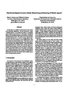
As a result, a failure of any single computer will not bring the whole system down. From the hardware point of view the DMCS is a multi-platform system consisting of a set of distributed computers connected via a local area network. Functionally, the system follows the traditional, hierarchical approach: graphical user interfaces and data analysis applications run under Unix while data acquisition and direct control run on so-called process control computers under the VxWorks [4] real-time operating system. Most of the system components are available on both platforms and there are plans to extend this functionality into the Windows-NT environment. The system accesses various hardware modules via the VME and GPIB instrumentation buses and transparently integrates PLC-based I/O systems.
1 INTRODUCTION
3 MODEL OF PROCESS UNDER CONTROL
The challenge the system designers faced was to produce an integrated system to serve as both a general-purpose monitoring and control system and a measurement tool. It means that the requirements traditionally imposed on the monitoring and control systems were accompanied by an additional requirement: to measure a multitude of intrinsically different process variables with varying accuracy, speed, and dynamic range. The system is required to monitor and control the environment while performing special tests and measurements. At the same time the R&D environment calls for a system that is flexible, reconfigurable, extendible, and scalable. In response to these requirements an open software platform for building multi-user distributed control and monitoring as well as test and measurement systems has been developed.
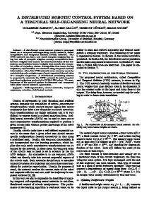
The state of the process under control is monitored and altered through manipulations on a set of process variables (PVs). Some process variables (input process variables) reflect directly measured process parameters, whereas other contain control values used to regulate the process (output process variables). Still other process variables called software process variables may contain system control parameters, internal system variables, statistics, long-term trends, etc. All PVs have calculations assigned to them. Each input and output PV is additionally associated with a data acquisition channel, signal conditioning device, and a sensor.
2 SYSTEM ORGANIZATION The Distributed Monitoring and Control System (DMCS) is a configurable set of communicating distributed objects. The following components constitute the core of the system: memory resident real-time data base, scan system with on-line processing capabilities, event and message communication subsystem, data archival subsystem, off-line analysis tools, and various user interfaces. The system is decentralized and, unlike in many other systems, no single computer assumes a central role.
4 SYSTEM OPERATION PRINCIPLES The system configuration is described using the Data Base Definition Language (DBDL). Currently, the system description includes four classes of objects: scans, process variables, devices, and calculations. DBDL enables the user to define all of the objects present in the system. The result configuration is loaded to the process control computers for interpretation. All objects are kept in the memory resident real-time data bases (RTDB) located in each of the process control computers.
Operated by the Universities Research Association under contract with the U.S. Department of Energy
0-7803-4376-X/98/$10.00 1998 IEEE
3713
4.1 Real-time Data Base
5 INTERACTIVE CONTROL
RTDB is a fast memory-resident object-oriented data base. It provides transparent access to local and remote objects via names, indices, and object attributes. It also contains a caching mechanism for remote objects and a locking mechanism to control access to the objects. 4.2 Scan System Monitoring, control, and data saving features of the DMCS are implemented through an elaborate scanning system offering coherent, device-independent I/O and powerful synchronization capabilities. The scan system links the real-time data base with the process under control by uniformly accessing devices and pseudodevices and passing the data to and from the RTDB. Advanced features of the scan system include time-driven and event-driven data acquisition and control, PV-based or device-based scanning lists, data saving scans, and PID control scans. All scans and their attributes are userconfigurable and can be monitored and manipulated in real-time. 4.4 Communication and Synchronization Scans, servers, and control clients communicate and synchronize through exchange of messages and events. The DMCS offers transparent system-wide eventbased communication and synchronization. Events are exchanged using a concept of a software bus where objects can communicate with each other without having direct knowledge of each other. In this scheme any active object (e.g., data acquisition scan) that wants to receive events, registers its interest in specific types of events. Events are multicast to all interested parties in a local computer as well as in remote computers. The mechanism of events is a primary way of synchronizing actions of all system active components- essentially all data acquisition scans and special measurement-type programs. The DMCS also provides uniform message-oriented data access based on a client-server model of cooperative computing. 4.5 Continuous control Continuous control is provided by the system through closed loop control using a PID algorithm. The PID algorithm is implemented as a calculation attached to a controlled process variable. The calculation is triggered whenever a new value of the process variable is requested, which happens periodically with a period defined for the appropriate scan. The system includes a dedicated user interface to tune and examine PID loops. Since implementing another control algorithm is as simple as adding a new calculation to the system the authors plan on supplementing the PID algorithm with a set of fuzzy logic control algorithms.
Modern data monitoring and control systems require sophisticated graphical user interfaces. Since X Windows and Motif are currently the dominant technologies for visualization on Unix workstations, they are the basis for the user-system dialog implementation. However, due to the advent of Java-enabled systems and the growing amount of Windows NT systems we are forced to consider a multi-platform user interface for future releases of the system. The DMCS provides users with several readily available universal user interfaces as well as with a set of tools to enable rapid development of animated process schematics and ad hoc user interfaces. The universal tools enable selecting and displaying values and attributes of any set of process variables, either graphically or numerically. Specialized user interfaces are developed with the help of graphical user interface builders, which significantly accelerates the development process. Examples of specialized user interfaces developed with these tools are fast data logging control panels, power control and monitoring user interfaces [3], quench detection, and magnet protection control panels. 6 BATCH CONTROL Special tests, non-standard operation sequences, and required system actions can be performed with the help of scripts. The scripts can be executed from any authorized Unix workstation. A set of programs has been specially created to facilitate the script development that enable event signaling, remote real-time data base accesses and inserts, remote invocation of VxWorks-resident functions, and current control. These programs constitute a powerful toolset to control the system in a batch mode. 7 DATA MANAGEMENT AND ANALYSIS In order to satisfy the real-time, as well as data archival and retrieval requirements, the DMCS adopts a hierarchical storage model. The model includes lightweight in-memory data bases to satisfy real-time requirements (RTDB), file system based intermediate storage, a commercial data base for day-to-day data management, and optical storage for long term data archival. At the current phase of system development the last two levels of the storage system are still under construction. Data collected by the DAQ subsystem is processed in real time before entering the RTDB. Therefore, all process variables can be monitored in real-time without any data processing on the client side. Archived data can be subjected to off-line processing and analysis.
3714
7.1 Chunk Format Standard The Chunk Format Standard, or CFS, is a hierarchical multi-object file format for storing diverse scientific data. The main requirement addressed in the design of CFS is the extensibility for future enhancements and capability to store any data. CFS enables easy merging of data by simply appending one CFS file at the end of another. Current implementation of the Chunk Format Standard includes both the Unix (SunOS) and VxWorks platforms. 7.2 On-line data processing The software system provides for real-time conversion of measured input voltages to engineering units, by applying calibrations and performing calculations. This on-line processing includes a mechanism similar to triggers found in relational data bases: Calculations of some quantities can in turn trigger automatic re-calculation of other quantities. This mechanism constitutes a powerful tool for implementing any algorithm and processing hierarchy while maintaining access to all required partial results. 7.3 Off-line data analysis Archived data can be interactively analyzed and visualized with the help of a universal data analysis program. This program can be used for plotting waveforms of individual data channels as well as for performing simple mathematical operations on single or combined waveforms prior to visualization. The user can extend the processing capabilities of this tool by adding any custom algorithms that later can be selected and applied interactively. Specialized data analysis and report generating tools that access data through the use of an appropriate API can be also constructed. A program to generate a quench summary for each accelerator magnet quench event is one of the examples of such tools. 8 APPLICATIONS OF THE SYSTEM
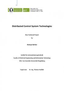
includes the following: an SSC 15 meter magnet test stand modified to perform 1.8K quench tests of a low beta quadrupole magnet, a standard Tevatron magnet test stand used to re-test Tevatron dipole magnets at 4.6K, and another Tevatron magnet test stand modified to include corrector magnets as part of a special cryogenic accelerator magnet heat leak study. In all three applications the parameters being measured were cryogenic temperatures, pressures, helium flow, helium vapor pressure, magnet current, and Idot. In addition, the low beta quad measurements also included strain gauges. 8.2 Vertical Magnet Test Facility The vertical magnet test facility [2] is another application of the DMCS system. This four meter vertical dewar is capable of testing superconducting magnets over a temperature range of 1.8K to 4.6K and can power these magnets up to 18kA. Helium valves are regulated through a feedback loop to control liquid helium level and temperature. In addition, a fast high voltage data logging system (quench characterization), a magnet quench detection and magnet quench protection system, and a power supply control and hardware interlock system are integrated to provide complete magnet power control and data acquisition. CONCLUSIONS Despite the fact that the full version of the DMCS is not yet available, the system has been already successfully applied to control and monitor several installations. The authors' experience from running the systems based on DMCS confirmed that the openness and flexibility of the design pays off when confronted with constantly changing R&D environment and tight schedules. ACKNOWLEDGMENTS The authors would like to thank all the users of the system for their valuable remarks, especially M.Lamm, T.Peterson, J.DiMarco, and M.Tartaglia.
The DMCS system has been successfully applied for monitoring and controlling the Horizontal and Vertical Magnet Test Facilities in the Fermilab Technical Division. The system is also expected to be used to control the Magnet Test Facility cryogenic plant.
[1]
8.1 Horizontal Magnet Test Facility
[3]
The DMCS was incorporated in the horizontal magnet test facility as an early application. This test facility
[4]
REFERENCES
[2]
3715
‘An Open Distributed Monitoring and Control System’, J.M.Nogiec et al. Proc. of the International Conference on Computing in High Energy Physics CHEP'97, April 1997, Berlin ‘A New Facility to Test Superconducting Accelerator Magnets in Superfluid Helium’, M.J.Lamm et al. Proc. of the 1997 Particle Accelerator Conference, Vancouver, Canada ‘An Embedded Power Supply Controller’, S.Sharonov, J.M.Nogiec, Proc. of the 1997 Particle Accelerator Conference, Vancouver, Canada ‘VxWorks Programmer's Guide 5.2’, Wind River Systems, Inc., 1995