A DSP-Based Vector Control of Five-Phase Synchronous Reluctance Motor Hamid A. Toliyat
Ruhe Shi
Huangsheng Xu
IEEE, , Senior Member
IEEE, Student Member
IEEE Student Member
Electrical Machines and Power Electronics Laboratory Department of Electrical Engineering Texas A&M University College Station, TX 77843-3128 Phone: (979) 862-3034 Fax: (979) 845-6259 E-mail:
[email protected] Abstract- In this paper, the mathematical model of a five-phase Synchronous Reluctance Motor (SynRel) is given. The well known winding function method is used to derive the winding inductances in order to develop the dynamic equations of SynRel in the natural frame of reference (a-b-c-d-e). The fivephase transformation from the stationary (a-b-c-d-e) reference frame to a rotating (d-q-D-Q-n) reference frame is developed to remove the angular dependency of the inductances. Later, voltage equations for the five-phase SynRel in synchronous rotating reference frame are developed. Based on the developed voltage equations, the equivalent circuits in the synchronous reference frame are also presented to better understand the operation of the motor drive. The torque in terms of currents is then obtained using the magnetic co-energy method. Indirect rotor flux field-oriented control is then developed for the fivephase SynRel motor followed by simulation results using Matlab/Simulink. The control block diagram of the proposed indirect vector control is also given in this paper. A five-phase SynRel motor plus the five phase current regulated space vector PWM (SVPWM) inverter are designed and fabricated in the laboratory. The control method is implemented the floatingpoint digital signal processor board TMS320C32 to verify the validity of the developed control strategy.
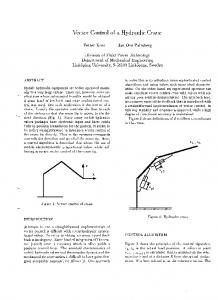
of several solid states devices form one leg of the drive. Therefore, the requirement of n separate drive units in a multi-phase system is not oppressive for large drives since many of the necessary components are presented in the contemporary designs. In general, synchronous reluctance motors can broadly be classified into axially laminated and radially laminated synchronous motors. These motors have the same stator construction as the multi-phase induction motors. The synchronous reluctance motor has recently attracted the efforts of researchers and is gaining more and more interest as a possible alternative for ac induction motor drives [1417]. Compared with the doubly salient structure of the switched reluctance motor, SynRel motor is structurally simpler with only rotor being salient while the stator is typically wound in an identical manner to an induction machine. It has also been shown that the torque density depends highly on this saliency ratio. Figure 1 shows a simple five-phase SynRel motor. a
Keywords: Five-phase synchronous reluctance motor, indirect rotor flux field-orientation, five-phase space vector PWM, digital signal processing. INTRODUCTION
ga
I.
-d
-c
qe
e
High phase number drives possess several advantages over conventional three phase drives such as: reducing the amplitude and increasing the frequency of torque pulsations, reducing the rotor harmonic currents, reducing the current per phase without increasing the voltage per phase, lowering the dc link current harmonics and higher reliability [1-9]. By increasing the number of phases it is also possible to increase the torque per rms ampere for the same volume machine [1013]. The high phase order drive is likely to remain limited to specialized applications where high reliability is demanded such as electric/hybrid vehicles, aerospace applications, ship propulsion and high power applications where a combination
b θ
qs,Ref
gb
-e
-b
d
c -a ds
Fig. 1
de
Five-phase SynRel motor with two-pole concentrated windings.
1 0-7803-6404-X/00/$10.00 (C) 2000
There are generally three types of rotor used in SynRel motors. They are segmental, flux barrier, and axially laminated structure. A SynRel motor has rugged simple structure, low manufacturing cost, possibility of high torque per unit volume, and the absence of rotor windings resulting in simple control schemes and decreased losses. Therefore, this kind of motor is an attractive candidate for numerous industrial and automotive applications [17]. II. SYSTEM EQUATIONS AND TRANSFORMATION The idealized structural representation of a five-phase two-pole reluctance motor is shown as Figure 1. It is assumed that iron saturation can be neglected and that only fundamental air gap flux is taken into account. In general, the equations which describe the electrical behavior of this machine in matrix form are expressed as follows: Stator voltage equation: V s = R s I s + pλ s where p = d
dt
(1)
I s = [i as
ibs
Vs = [v as
vbs
λ bs
ics v cs
λ cs
i ds
ies ] ,
v ds
λ ds
2π 5
cos
4π 5 2π cos 5
4π 5 4π cos 5 2π cos 5
cos
1 2π 5 4π cos 5 4π cos 5 cos
cos
1 2π 5 4π cos 5 cos
1 2π 5
cos
2π 5 4π cos 5 4π cos 5 2π cos 5 cos
1
+
4π 2π 2π 4π ) cos 2(θ − ) cos 2(θ + ) cos 2(θ − ) 5 5 5 5 2 2π 4π cos 2(θ − π ) cos 2(θ + ) cos 2(θ − ) cos 2θ 5 5 5 2π 4 4π cos 2(θ + ) cos 2(θ − π ) cos 2θ cos 2(θ + ) 5 5 5 4π 4 2π cos 2(θ − ) cos 2θ cos 2(θ + π ) cos 2(θ − ) 5 5 5 4π 2π 2 cos 2θ cos 2(θ + ) cos 2(θ − ) cos 2(θ + π ) 5 5 5
cos 2θ 4π cos 2(θ + ) 5 bπ 2π * cos 2(θ − k ) 2 5 2π cos 2(θ + ) 5 4π cos 2(θ − 5 )
cos 2(θ +
(3) where, L!s is the stator leakage inductance and θ is the rotor position with respect to the reference axis. The parameters “a” and “b” are the air gap coefficients, which are given by a=
and
λ s = [λ as
1 2π cos 5 4π L (θ ) = ka π cos 5 4π cos 5 2π cos 5
t
1 1 1 ( ) + 2 g a gb
, b=
2 1 1 ( ) − π g a gb
(4)
The inductance coefficient is given by
v es ]t ,
k=
λ es ] . t
Stator flux linkage equation:
λ s = Lss I s Also Rs=rsI, where I is a 5 by 5 identity matrix and rs is the stator resistance of each coil, assuming that all stator coils are similar. The inductance matrix Lss is a symmetric 5 by 5 matrix given by Laa Lab Lac Lad Lae L ab Lbb Lbc Lbd Lbe (2) L ss = Lac Lbc Lcc Lcd Lce L L L L L bd cd dd de ad Lae Lbe Lce Lde Lee Using the well-known winding function method [18], the above winding inductance matrix can be summarized as follow: L ss = L!s I − L (θ ) where L(θ) is a 5 by 5 symmetric inductance matrix. It is a function of the rotor position θ given by (3). It also consists of two parts. The first part is constant and the second part is
4 µ 0 r!N 2
π2
with r being the stator inner radius, ! the effective stator stack length, and N the number of stator windings in series. It is clear that the inductance matrix Lss varies with the rotor position because of the salient structure of the rotor. In order to remove this dependency, a transformation matrix, T(θ),from stationery (a-b-c-d-e) reference frame to a rotating (d-q-D-Q-n) reference frame is proposed to simplify the windings inductance matrix. That is,
FqdQDn = T (θ ) Fabcde where, F can be either Vs or Is. The proposed transformation matrix T(θ) is given by the following 5 by 5 matrix: cos θ sin θ 2 T (θ ) = 1 5 0 1 2
2π ) 5 2π sin( θ − ) 5 2π cos 5 2π sin 5 1
4π ) 5 4π sin( θ − ) 5 4π cos 5 4π sin 5 1
4π ) 5 4π sin( θ + ) 5 4π cos 5 4π − sin 5 1
cos( θ −
cos( θ −
cos( θ +
2
2
2
rotor position dependent.
2 0-7803-6404-X/00/$10.00 (C) 2000
2π ) 5 2π sin( θ + ) 5 2π cos 5 2π sin − 5 1 2
cos( θ +
(5)
It is easy to prove that this transformation matrix has the following pseudo-orthogonal property as T
−1
5 (θ ) = T (θ ) . 2
The transformation presented in (5) can be applied to the five-phase voltage equation given by (1). The voltage equations in terms of flux linkages in synchronous rotating (d-q-D-Q-n) reference frame are given by d λ qs V qs = r s i qs + ωλ ds + dt d λ ds V ds = r s i ds − ωλ qs + dt d λ Qs (6) V Qs = r s i Qs + dt d λ Ds V Ds = r s i Ds + dt d λ ns V ns = r s i ns + dt
are all zero sequence equivalents circuits and do not contribute to torque production. The equivalent circuits responsible for establishing torque and the magnetizing flux in the machine are the q-axis and d-axis equivalent circuits. Using the transformation presented by (5), we have been able to successfully remove the dependency of the inductances on the rotor position. It is also clear from Figure 2 that there is no coupling between the q-axis and d-axis equivalent circuits. Therefore, developing the control algorithm to control this five-phase SynRel should not be very complicated. These equivalents circuits are used to develop the rotor flux fieldoriented control for the salient pole five-phase SynRel motor. rs
L ls
-
+
+
iqs
V qs
iQs
L mq
q-axis equivalent circuit ωλ qs
rs
-
+
Q-axis equivalent circuit
L ls
L ls
[ i qdQDs = [i qs
λ ds
(7)
i ds
λQs iQs
λ Ds
i Ds
iDs
L md
D-axis equivalent circuit
rs
]
λ ns ,
+
]
i ns t .
L qdQDs
n-axis equivalent circuit
Fig. 2
Equivalent circuits of the five-phase SynRel in the synchronous reference frame.
III. ELECTROMAGNETIC TORQUE
0 0 0 Lls 0
0 0 0 0 Lls
(8)
Finally, the q-axis and d-axis self and mutual inductances are given by,
Lqs = Lls + Lmq , Lds = Lls + Lmd , Lmq =
ins
-
where, the inductance matrix in the newly defined synchronously rotating reference frame is given by,
0 0 Lls 0 0
L ls
V ns
LqdQDs = T (θ ) Lss T (θ ) −1
0 L ds 0 0 0
V Ds -
t
Now, by using the proposed transformation matrix T(θ) the winding inductance matrix can be simplified as
L qs 0 = 0 0 0
rs +
ids
d-axis equivalent circuit
λ qdQDs = λ qs
V Qs
-
V ds
where,
rs
L ls
+
The stator flux linkage equation in matrix form is given by
λqdQDs = LqdQDs iqdQDs
ωλ ds
+
5 b 5 b Kπ (a − ) , Lmd = Kπ (a + ) . 2 2 2 2
Based on (6) the equivalent circuits for the five-phase SynRel machine can be described as shown in Figure 2. Notice that the Q-axis, D-axis, and n-axis equivalent circuits
The reluctance torque is created by the alignment of the minimum reluctance path of the rotor with the rotating magnetizing MMF, which is only produced by the stator currents. Namely, when stator windings are supplied with a set of five-phase balanced currents a synchronously rotating air-gap flux is produced. As the rotor rotates in synchronism with the stator air-gap flux, electromagnetic torque is developed in order to align the minimum magnetic reluctance path of the rotor with the rotating air-gap flux. However, if the motor is loaded the rotor begins to lag the rotating air-gap flux thus producing the misalignment of the minimum reluctance path and the rotating air-gap flux. Therefore, the developed electromagnetic torque will increase in order to minimize the reluctance of the magnetic path. When the electromagnetic torque is equal and opposite to the load toque on the rotor, the rotor will again rotate at synchronous speed. The mechanical equation of motion depends on the characteristics of the load, which may differ widely from one application to another. It is assumed, for simplicity, that the load torque consists only of an inertial torque and a constant load torque. The mechanical motion equation can be simply expressed as
3 0-7803-6404-X/00/$10.00 (C) 2000
J
dω rm = Tem − TL − T f dt
(9)
where ωrm is the rotor angular speed, J the rotor inertia, Tf the friction torque, TL the load torque and Tem the electromegnetic torque produced by the machine. The electromagnetic torque can be found using the magnetic co-energy method,
times so that the actual voltage vector follows the reference vector. The conduction times for the first and second non-zero vectors, and also the zero vectors are given by: Vref sin( k * 36 " − α )
ta =
V sin 144 "
Ts
(12)
Imaginery
Tem
∂Wco P ∂L 5 = = [T (θ ) I S ]t T (θ ) SS T (θ ) −1[T (θ ) I S ] (10) 4 2 ∂θ r ∂θ r
(00011)
which finally can be simplified as
(00111)
P5 P 5 Lds − Lqs ( Lmd − Lmq )ids iqs = Tem = λds iqs 2 2 2 2 Lds
(10011)
(10111)
(11)
(01011) (00010)
(10010)
(00101)
Here, we can easily see the effect of rotor saliency on the developed torque. The higher the saliency ratio Ld/Lq, the highr the elctromagnetic torque will be. In other words, in order to increase the torque density and the effiency of SynRel the saliency ratio Ld/Lq has to be high, and also (LdLq) needs to be high. However, there is a physical limit to this ratio with such structure since the maximum value of Ld is the synchronous inductance and the minimum value of Lq is the stator leakage inductance.
(10001)
(00001)
(11011)
(10101)
(01111) (10110)
(01001) (10000)
(00110)
(11001) qs,Real
(11010)
(01010)
(11101)
(00100) (01101)
(01110)
(10100) (01000)
(11110)
(01100)
(11000)
(11100) ds
Fig. 3
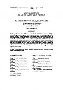
Thirty non-zero switching vectors for five-phase reluctance motor.
IV. ROTOR FLUX FIELD ORIENTATED CONTROL USINF SPACE VECTOR PWM STRATEGY
V4
In five-phase voltage source PWM inverters there are totally thirty non-zero switching vectors, compared with six non-zero vectors available in three-phase PWM inverters. Moreover, there also exist two zero switching vectors. The non-zero vectors are shown in Figure 3. It is assumed that the reference axis is the same as a-phase axis and q-axis, and that q-axis leads d-axis by 90°. The coordinates attached to these vectors correspond to the switching states of the upper phase inverter switches with "1" representing a switch being on and a "0" showing a switch being off, from phase A to phase E respectively. All these thirty vectors are located as the vertexes on three decagons. The only difference among the three decagons is the length of the sides. The ratio of the amplitudes is 1:1.618:1.6182, from the smallest one to the largest one, respectively. However, it is easy to see that only one switching is needed from one vector to either of the two nearby vectors for the largest decagon, as shown in Fig. 4. In this case, minimum switching loss and maximum switching frequency can be achieved at the same time. For simplicity the ten largest vectors are chosen to regulate the motor currents. These vectors are the basis for implementing the space vector pulse width modulation (SVPWM) used in the simulation study. For every switching time interval Ts, two non-zero vectors adjacent to the reference vector Vref and two zero-vectors are selected. These vectors will be used with their specific conduction
V3 (10011)
(00011)
V5
V2
(10001)
(00111)
tb/Ts Vref
α
V6 (00110)
(11001)
ta/Ts
V1
qs
(11000) V7
V10
(01110)
(11100) (01100) V8
V9
ds
Fig. 4
Ten switching vectors for SVPWM of five-phase machines.
tb =
Vref sin(α − (k − 1) * 36 " ) V sin 144 "
t 0 = Ts − t a − t b
Ts
(13) (14)
where, k is the sector number that the reference vector is located in. The valid range for k is from 1 to 10 as these ten vectors divide the dq plane into ten sectors. The angle α is
4 0-7803-6404-X/00/$10.00 (C) 2000
defined as voltage vector angle with respect to the reference axis in the synchronously rotating reference frame. Its value can be between 0 and 2π radians. From (6-8) the q-axis and d-axis voltage equations at steady state can be obtained from di qs V qs = rs i qs + ωλ ds + Lqs (15) dt V ds = rs i ds − ωλ qs + Lds
di ds dt
(16)
The electromagnetic torque in terms of stator q-axis and d-axis fluxes using (11) is given by Tem =
P5 (λds iqs − λqs ids ) 2 2
(17)
Now, using a rotor flux field-oriented control strategy, λ qs = 0 , and (17) can be simplified to iqs =
Tem kT λds
kT =
P5 . 2 2
(18)
corresponding to the commanded speed reference. Figure (8f) is the developed electromagnetic torque, which clearly follows the q-axis current. Figure (8-g) shows the stator phase “a” current in the stationery reference frame. Figure (8h) is the stator phase “a” terminal voltage with stator line-toline voltage depicted in Figure (8-i). Satisfactory results are obtained for every mode of operation. The prototype motor, which was fabricated in the laboratory is a five-phase, 7.5 hp, 4-pole SynRel motor as shown in Figure 5. It has 40 stator slots, four poles with stator phases being 72° apart. A five-phase current regulated PWM inverter was also fabricated in the laboratory. The basic power circuit topology is shown in Figure 6. There are totally 10 IGBTs plus corresponding gate drives needed to fabricate this inverter. The overall control algorithm was implemented on the TMS320C32 digital signal processor board for implementing the control algorithm [20]. A hysteresis current regulator was used to generate the commanded motor currents. Figure 9 shows the motor phase “a”, “b”, and “c” currents and the phase “a” terminal voltage.
where,
From (15-16) and (18) an indirect rotor flux field-oriented vector control is developed to control the SynRel motor as shown in Figure 7. The control system consists of the fivephase transformation given by (5) and a five-phase current regulated PWM. In the control block diagram, there is one speed regulator whose input is the speed error and output is the reference torque. Using (18) the q-axis reference current can be calculated. Also, in this block diagram there are two other current regulators whose inputs are d-axis and q-axis currents errors respectively. From (15-16) their outputs are daxis and q-axis reference voltages accordingly. By using the proposed transformation from synchronous rotating reference frame to stationery reference frame the specific switching pattern can be selected to trigger the ten IGBTs of the fivephase inverter. V. SIMULATON AND EXPERIMENTAL RESULTS
Fig. 5
A+
L
The control algorithm presented in the previous section plus the five-phase SynRel motor including the five-phase current regulated space vector PWM have been simulated in Mathlab/Simulink environment [19]. Figure 8 illustrates the simulation results for run-up and speed reversal under full load and also a load removal. Figure (8-a) shows the d-axis current, which is kept constant at 5A to develop the rated voltage in the machine. Figure (8-b) displays the load torque, which is constant for 900 milliseconds and then drops to zero. Figure (8-c) illustrates the shaft reference speed from start-up to rated speed, and then a speed reversal under full load. Figure (8-d) is the actual rotor speed, which follows exactly the commanded speed. Figure (8-e) illustrates the q-axis current
Five-phase SynRel motor. B+
C+
D+
E+
C
A−
B−
C−
D−
2 1
Fig. 6
5 0-7803-6404-X/00/$10.00 (C) 2000
E−
3
5-Phase SynRel Motor
Five-phase PWM inverter.
4 5
λ*ds
1 Lls + Lmd
+ *e ds
i
i
ω r* +
PI
+ -
PI
Vds*e
ωr λ
e qs
e ds
iqs*e + 1 KT λeds
Te*
ωr
+ + ω r λeds
iqse
Five Phase PWM Inverter
to abcde PI
-
dqDQn e
Five Phase Synchronous Machine
Vqs*e
θr Lqs
∫
θr
iqse
i
e ds
i as
abcde to
i bs
i cs i ds
dqDQn e
i es
Lds
Fig. 7
Speed Sensor
ωr
Block diagram for indirect rotor flux field-oriented control of five-phase SynRel Motor.
10
ieds
5 0 40
Tl
ω ref ωr i eqs
20 0 2000 0 -2000 2000 0 -2000 20 0 -20 50
Te
0 -50 20
i as v as v ab
0 -20 500 0 -500 500 0 -500
0
0.1
0.2
0.3
0.4
0.5 Time (sec.)
0.6
0.7
0.8
0.9
1
Fig. 8 Top to bottom: (a) Stator d-axis current in synchronously rotating reference frame (A),(b) Load torque (Nm), (c) Reference shaft speed (rpm), (d) Motor shaft actual speed (rpm),(e) Stator q-axis current in synchronously rotating reference frame (A),(f) Develpoed electromagnetic torque (Nm),(g) Stator phase "a" current (A), (h) Stator phase voltage (V), (i) Stator line-to-line voltag (V).
6 0-7803-6404-X/00/$10.00 (C) 2000
[4]
[5]
[6]
[7]
[8]
[9]
[10]
[11] Figure 9. Top to bottom, a) Phase C current (2A/div), b) Phase D current (2A/div), c) Phase E current (2A/div), d) Phase E voltage (20V/div).
VI.
[12]
CONCLUSIONS
In this paper, the d-q-D-Q-n model of a five-phase SynRel motor is described. A five-phase transformation for simplifying the machine equations in the a-b-c-d-e frame of reference and transforming them into d-q-D-Q-n space is proposed. The final equations in the newly defined d-q-DQ-n space plus the respective equivalent circuits are shown. This simplified model is used to develop the rotor flux fieldoriented control of five-phase synchronous reluctance motors. Simulation results are shown to support the developed theoretical field-oriented model. Furthermore, the validity of the overall control system has been partially proved in the laboratory by fabricating a five-phase SynRel motor and a five-current regulated PWM inverter. The control algorithm based on a TMS320C32 digital signal processor has been developed. Further experimental tests are underway at our laboratory to fine tune the controllers, and the results will be presented in a subsequent paper.
[13]
[14]
[15]
[16]
[17]
[18]
[19]
ACKNOWLEDGMENT This material is based in part upon work supported by the Texas Advanced Research Program under Grant No. 000512-0079-1999, and Office of Naval Research under Grant No. N00014-98-1-0717.
[20]
M. A. Abbas, R. Christen, and T.M. Jahns, "Six-Phase Voltage Source Inverter Driven Induction Motor," IEEE Trans. Ind. App., vol. IA-20, No. 5, Sep./Oct. 1984, pp. 1251-1259. E.A. Klingshirn, "High Phase Order Induction Motors-Part I and II," IEEE Trans. Power App. Sys., vol. PAS-102, No. 1, Jan 1983, pp. 4759. E. Klingshirn, " Harmonic Filters for Six-Phase and Other Multiphase Motors on Voltage Source Inverters," IEEE Trans. Ind. App. vol. IA21, No. 4, May/June 1985. P. Ferraris, M. Lazzari, and F. Profumo, "Phase Number of InverterFed Induction Motors : Effects on the dc Link Harmonics Contents," First European Conference on Power Electronics and Applications, 1618 October, 1985, pp. 3.95-3.102. H. Weh, and U. Schroder, "Static Inverter Concepts for Multiphase Machines with Square-wave Current Field Distributions," First European Conference on Power Electronics and Applications, Brussels, 16-18 October, 1985, pp. 1.147-1.152. K.N. Pavithran, R. Parimelalagan, and M.R. Krishnamurthy, "Studies on Inverter-Fed Five-Phase Induction Motor Drive," IEEE Power Elec., vol. 3, No. 2, Apr. 1988, pp. 224-235. J. Dente, “Induction Motor-Current Source Inverter Systems with Phase Number Greater Than 3,” First European Conference on Power Electronics and Applications, 16-18 October, 1985, pp. 3.143-3.147. H.A. Toliyat, T.A. Lipo, and J.C. White, "Analysis of a Concentrated Winding Induction Machine for Adjustable Speed Drive Applicationspart II (Motor Design and Performance)," IEEE Transactions on Energy Conversion, vol. 6, No. 4, pp. 685-692, Dec. 1991. H.A. Toliyat, L.Y. Xue, and T.A. Lipo, "A Five Phase Reluctance Motor with High Specific Torque," IEEE Transactions on Industry Applications, vol. 28, No. 3, pp. 659-667, May/June 1992. P.J. McCleer, J.M. Bailey, J.S. Lawler, and B. Banerjee, "Five Phase Trapeziodal Back EMF PM Synchronous Machines and Drives," Fourth European Conference on Power Electronics and Applications, Italy, 1991 , pp. 4.128-4.133. L. Xu and B. Wang, "Comparison Study of Rotor Structures for FivePhase Synchronous Reluctance Machines", Proceedings of the 1999 IAS Annual Meeting, pp. 1-8. L. Xu, X. Xu, T.A. Lipo, and D.W. Novotny, "Vector Control of a Synchronous Reluctance Motor Including Saturation and Iron Loss", IEEE Trans. on Industry Applications, Vol. 27, No. 5, pp. 977-985, 1991. H.A. Toliyat, "Analysis and Simulation of Five-Phase Variable -Speed Induction Motor Drives Under Asymmetrical Connections", IEEE Trans. of Power Electronics, Vol. 13, No. 4, pp. 748-756. A. Vagati, "The Synchronous Reluctance Solution: A New Alternative in A.C. Drives", IEEE Industrial Electronics, Control and Instrumentation, Vol. 1, pp. 1-13, 1994. N.A. Al-Nuaim, and H.A. Toliyat, “A Novel Method for Modeling Dynamic Air-Gap Eccentricity in Synchronous Machines Based on Modified Winding Function Theory,” IEEE Transactions on Energy Conversion, Vol. 13, No. 2, June 1998, pp. 156-162. C. Ong, Dynamic Simulation of Electrical Machinery Using Matlab/Simulink, Prentice Hall 1997. User’s Guide – TMS320 Floating-Point DSP Assembly Language Tools, TI Inc.
REFERENCES [1] [2]
[3]
E.E. Ward, and H. Harer, "Preliminary Investigation of an Inverter-Fed 5-Phase Induction Motor," Proc. IEE, vol. 116, No. 6, 1969, 980-984. T.M. Jahns, "Improved Reliability in Solid-State ac Drives by Means of Multiple Independent Phase-Drive Units," IEEE Trans. Ind. App., vol. IA-16, May/June 1980, pp. 321-331. P. Ferraris, and M. Lazzari, "Phase Numbers and Their Related Effects on the Characteristics of inverter Fed Induction Motor Drives," in Conf. Rec. 1983 IEEE Ind. Appl. Soc. Ann. Mtg., pp. 494-502.
7 0-7803-6404-X/00/$10.00 (C) 2000