Yicha ZHANG*, Ramy HARIKâ , Wout DE BACKERâ , Alain BERNARD*. *IRCCyN, Ecole Centrale de Nantes, Nantes, France. â University of South Carolina, ...
Solid SolidFreeform FreeformFabrication Fabrication2016: 2016:Proceedings Proceedingsof ofthe the27th 27thAnnual AnnualInternational International Solid Freeform Fabrication Symposium – An Additive Manufacturing Conference Reviewed Paper
A FACET CLUSTER-BASED METHOD FOR ALTERNATIVE BUILD ORIENTATION GENERATION IN ADDITIVE MANUFACTURING Yicha ZHANG*, Ramy HARIK†, Wout DE BACKER†, Alain BERNARD* *IRCCyN, Ecole Centrale de Nantes, Nantes, France †University of South Carolina, Columbia, South Carolina, USA Abstract Build orientation determination is an important pre-processing step in Additive Manufacturing. To identify an optimal build orientation, there are two main tasks, generating a set of alternative orientations and evaluating these alternatives with pre-set criteria. To solve the first task, currently there are two categories of methods, exhaustive computing and continuous surface decomposition. However, for exhaustive computing methods, the infinite original alternative orientation space is an obstacle, especially when considering multiple objectives. While the other type of methods have difficulty on surface separation and shape boundary recognition when facing complex CAD models. To tackle of these obstacles, this paper introduces a new method applying a statistical tool to form facet clusters for decomposing an STL model in a discrete way. The formed facet clusters can be used to efficiently generate meaningful alternative build orientations and can also be used to predict surface quality distribution over a part model for further process planning or design iteration. Introduction Additive Manufacturing (AM) has become a popular processing technology recently in many application domains [1]. Using a layer-by-layer additive building way, it can deal with parts with extremely complex geometries and internal structures. This brings it a great advantage for processing high-value and highcustomized parts [2]. Meanwhile, the design freedom has been increased due to the decreased processing constrains on geometry [2-4]. As a digital manufacturing, AM is totally data-driven, which makes it seem that inputting a digitized CAD model can result to a final prototype or component in a fully automated way by only pushing a start bottom in the AM machine. However, except geometric constraints, in order to obtain a good production quality, there are still many other constraints that should be considered. For example, the intrinsic ‘step-effect’ and the anisotropic material properties, caused by layered building, need to be analyzed when designing or manufacturing. In the processing AM chain, there is a critical step to transfer a CAD data model into a processing data model which can be directly used by AM machines. This critical step is pre-processing, also called process planning [5, 6]. Among diverse process planning tasks, build orientation optimization is the most important one since it determines along which direction the materials will be added. This will affect the later slicing, scanning or tool-path generation results as well as the final production results, including build time, cost and quality. Mathematically, the build orientation determination problem can be defined as: for a given object, CAD model, in its original orientation (design orientation), to find a transformation matrix, T, such that after applying the transformation to the model, the build direction lines up along vertical axis (Z, material adding orientation). To determine the matrix, there are two main tasks: generating alternative build orientations from the infinite original solutions space and evaluating the generated alternatives with preset preference and criteria. The final optimal build orientation selected from the alternative build orientation set can be used to calculate the transformation matrix for the original model. In real AM production practice, usually the AM machine setup and user or designer preferences are not changed or limited to some standard options but only the AM operators are shifted. Users only need to determine an optimal build orientation for a part model by using their own knowledge. However, a same given part model to be manufactured by the same AM machine, different operators may determine different optimal build orientations respectively. This would cause production stability problem, which means the production results would be different. This production stability problem would further prevent the industrialization of AM. The main reason why different optimal build 23
orientations are generated by different operators would be that the alternative build orientation sets generated respectively by different operators are different. If a method can generate a relatively stable alternative orientation set, which contain the optimal orientation implicitly, different operators can identify the same optimal build orientation by using the same preset setup, preference and evaluation criteria as input of decision making. As a result, the production result would be stable. Therefore, the purpose of this paper is to introduce such kind of method for generating a stable alternative orientation set to solve the first task of build orientation optimization and also facilitate the other task. The method is to decompose a CAD model represented in STL format into a set of facet clusters in a discrete way, which is different to currently used feature-based method using continuous decomposition manner. The obtained facet clusters will be used to generate alternative build orientation for the original non-decomposed original CAD model. To form reasonable facet clusters, a statistical non-supervised learning scheme is adopted. With the proposed method, both simple and complex CAD models can be decomposed quickly into facet clusters, which will be demonstrated by examples later in this paper. Before introducing the proposed method, the next section of this paper reviews current solutions in literature and shows the necessity of applying the proposed method. Related Works In literature, there are plenty of proposed solutions for build orientation optimization problem since the beginning of AM. Some authors had already conducted comprehensive reviews on orientation optimization study [7, 8]. Hence, this section will not present another comprehensive review work of those methods but mainly discuss about the existing solutions for the first task, generating alternative build orientation set. Theoretically, an STL CAD model can be rotated freely within a build envelope of an AM machine if it can be fitted. Hence, the unlimited continuous rotation degrees around two axes except the build axis, Z, result to an infinite alternative build orientation set. However, the infinite orientation set cannot be directly used for the later evaluation task due to the computation cost. To solve this problem, researchers tried different methods to extract a finite alternative build orientation set or a reduced infinite orientation set from the theoretically infinite one. The simplest way is to specify a small list of alternative build orientations by rotating the original part model with an interval. In the literature, some researchers applied this method to generate alternative build orientations for layout and orientation optimization [9-11]. However, this cannot guarantee the optimality since the big interval would cause the missing of potential optimal candidates. Hence, to avoid missing the potential optimal orientation, some researchers tried to specify the orientations in a small interval or even in a continuous way by using a continuous control parameter. Hur et al. [12] developed an exhaustive computation method for orientation optimization with the minimum build height as an optimization objective. Alternative build orientations were generated by rotating the part model about two axis with a given rotation interval of 5 degrees. In [13], a statistical method, response surface methodology, was proposed to deal with the build style of SLA. In this method, build orientation was regarded as a continuous parameter controlled by a user-defined ‘Z-height’ range to be optimized. Therefore, the orientation generation manner in their method is also a user specification. However, due to the infinite and continuous orientation space theoretically, reducing interval or specifying a limited continuous orientation range can neither guarantee the global optimality. To deal with this problem, intensive work had been conducted to apply advanced computation method for single- or multipleobjective optimization for identifying the global orientation. The application of genetic algorithm is a representative [14-22]. In these works, alternative orientations were generated by using diverse genetic operators in a stochastic searching way and a fitness function, derived from orientation evaluation criteria, was designed for selection. For single-objective optimization, this kind of method can identify the optimal build orientation with an acceptable computation cost. But, for multi-objective optimization, the exhaustive computing is not efficient [8, 21]. As stated by Padhye and Deb [21], a possible route to arrive at the optimal orientation without carrying out exhaustive computation is to analyze the features of a solid object. Therefore, using surface shape or features of the part model to generate alternative build orientations is another group of methods. In the beginning, part model’s convex hull was used to generate alternative build orientations. The planar surface or facet on the part model which are in the common plane with the part model’s convex hull is used as a base, of which the perpendicular orientation is identified as an alternative build orientation. A couple of representative works can be found in [23-26]. These methods can extract meaningful planar surfaces on a part model to generate a set of practical alternative build orientations. However, other concave surfaces may 24
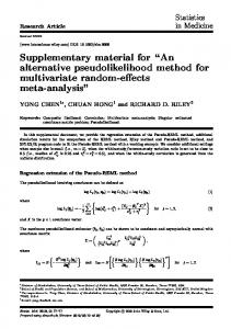
also imply some potential practical or even optimal build orientations. To avoid missing these possibilities, some researchers focused on using the original part model to generate alternative build orientations. In [27-29], the planar surfaces on the part model were directly used to generate vertical directions as alternative build orientations. An extreme example was reported by [30], where each triangular facet of an STL model was used to generate an alternative build orientation along the facet’s normal direction. These methods can generate more alternative build orientations, especially the method of using facet normal. However, for part models with nonplanar surfaces or meaningful shape features, these methods would encounter problem to identify additional orientation candidates implied by these surfaces or features. As stated by Zhang and Bernard [8], in real practice, not all the surface shapes of a part model were treated equally but more attention would be paid to some local critical shape features, which implies the importance to analyze the shape features of part model in process planning. Hence, since the beginning, many researchers have investigated the using of shape features to generate alternative build orientations for optimization in AM. Frank and Fadel [31] defined 9 types of geometric features and associate a feature axis, which was used to indicate an alternative build orientation, for each defined type. In [32, 33], key geometric features or typical surface features of an STL model were used with associated rules to generate alternative build orientations for generating optimal orientations. Featurebased methods can generate meaningful alternative build orientations so as to capture the design intention [8, 34]. However, in feature-based methods, the definition of surface feature or key surface features is not very clear to be practical. In addition, in these researches, each surface feature can only generate a fixed alternative orientation, which cannot meet the requirements of different AM processes. Since the constraints on a same shape feature may be different when using different AM processes for production. This requires a shape feature can generate different alternative orientations in different processing contexts. To tackle of these drawbacks, Zhang et al. [8, 35-38] proposed to defined specific shape features for AM as AM features to solve the process planning and design problems. User-defined AM features can generate a set of finite alternative build orientations by using the shape boundary and facet normal information as well as user preference. However, the main difficulty of feature-based methods is feature recognition due to the insufficient topological information of STL part models, especially for part models with complex geometries. In general, the discussed methods above can be summarized as two main groups: one is exhaustive computing and the other is continuous surface decomposition. Exhaustive computing methods means the generation of alternative orientations is similar to Enumeration method. For this group of methods, if the number of generated alternatives is small, the optimality of result cannot be guaranteed since a large section of the original solution space would not be explored. But, if the number of generated alternatives is large, the later computation of orientation evaluation would be ineffective, especially when facing multi-objective optimization. In addition, for this kind of method, much computation is spent on evaluating meaningless alternatives. Continuous surface decomposition means to decompose an STL model into a set of surface fragments (facets, planar surfaces or special shape features), which are composed of a set of adjacent flat facet triangles. This group of method uses decomposed surface fragments and associated rules to generate alternative build orientations. In this way, meaningful alternative build orientation can be generated and further computation of orientation evaluation can be saved. However, as discussed above, how to decompose an STL model in a continuous way to form meaningful predefined shape features is difficult. Current feature recognition methods can only recognize simple shape features due to the lack of topological information in STL files [39]. Hence, the decomposition method should be improved. The purpose of this paper is to introduce a new decomposition method to fraction an STL model in a discontinuous way so as to help generate alternative build orientations. The next section of this paper presents the new method. Facet Clustering Method Currently, STL format is still the most widely-used in AM as a de-facto standard though some new formats, e.g. 3MF, have been developed. Hence, the proposed new decomposition method is based on this format. By using STL format, a 3D CAD model can be represented by a set of numbered triangular faces with normal and color information. A facet in ASCII STL format can be described by Figure 1 below. 25
Figure 1, representation of a facet in ASCII STL According to the planar characteristic of triangular facet in an STL model, it could be imaged that the best way to fabricate a single facet with AM processes is to align the facet’s normal direction along build orientation (‘Z’ direction) or make it perpendicular to the build orientation to avoid the stair-step effect caused by layered manufacturing. If the facet is placed in an inclined direction to the build orientation, the stair-step effect would appear. Stepping further, when fabricating a full part model in STL format, to reduce the total impact of stairstep effect on the surface roughness or shape accuracy, it is better to orientate the part model in a direction under which the number of inclined facets is the smallest. Traditionally, a full STL model would be decomposed into a set of adjacent triangles to represent predefined shape features or pre-identified key surfaces. Then, a couple of orientation rules would be associated to these decomposed surface fragments to generate potential optimal build orientations to benefit these fragments. Finally, these generated orientations are used as alternative build orientations for the original full STL model. As discussed above, one difficulty for the continuous decomposition method is the low efficiency of feature recognition due to the insufficient geometric information of STL file. Another ignorance of these methods is that they only considered to separate the STL model in a continuous way but never tried to analyze different disconnected surfaces which may have similar characteristics on the same model in a discrete way. In an STL model, different disconnected surfaces may have parallel or coaxial characteristic, which makes these surfaces have a similar production results (Figure 2).
Figure 2, disconnected parallel and coaxial surface shapes In Figure 2, if applying traditional continuous decomposition, the two pairs of surfaces would result to four independent surface features, two cylindrical and two planar surface features. However, they would generate similar alternative build orientations for the part model. This will produce duplicate alternative orientations to waste more computation in the orientation evaluation stage. But, if the disconnected parallel planes or coaxial cylindrical surfaces are grouped as one surface feature, the duplicate alternative orientation for the part model would be reduced. Actually, in real practice, the build orientation would have similar impact on the grouped surface features. Therefore, in this paper, facet cluster is proposed to describe this kind of disconnected surface feature group. And then applying orientation rules to the facet cluster for generating potential optimal build orientations to benefit the cluster as did for traditional continuous surface features in [8, 31]. However, how to cluster facets in a reasonable way? This is the core question for this paper. To answer this question, there are 26
two tasks to do: one is the formation of a facet cluster by using limited geometric information of an STL model and the other is the identification of a suitable number of clusters for the STL model. To form a facet cluster, the normal information of the facet is used. In this paper, according to the characteristics of layered manufacturing, an assumption is made that the build orientation would have similar impact on those facets, which have similar normal directions, of an STL model. Based on this point, facets which have similar normal directions should be clustered as one group for production quality analysis. Here, similarity between a pair of facets is measured by the angle between their two normal directions. To compute the similarity among triangular facets of an STL model, a classical statistical clustering method, K-means, is adopted. K-means is an unsupervised learning algorithm that solves the well-known clustering problem [40, 41]. The clustering procedure follows a simple and easy way to classify a given data set through a certain number of pre-determined clusters (assume k clusters). The main idea is to search for k centers from the given data set, one for each cluster. These centers should be placed in a cunning way because of different location causes different result. So, the optimal choice is to place the centers as much as possible far away from each other. The next step is to take each point belonging to a given data set and associate it to the nearest center. When no point is pending, the first step is completed and an early group age is done. At this point there is a need to re-calculate k new centroids as barycenter of the clusters resulting from the previous step. After obtaining these k new centroids, a new binding has to be done between the same data set points and the nearest new center. A loop has been generated. As a result of this loop, the k centers change their location step by step until no more changes could be done or in other words centers do not move any more. In this way, the given data set is divided into k stable sub-clusters. Mathematically, given a set of data points (x 1 , x 2 , …, x n ), where each data point is a d-dimensional real vector, K-means clustering aims to partition the n data points into k (≤ n) clusters C = {C 1 , C 2 , …, C k } so as to minimize the within-cluster sum of squares (sum of distance functions of each point in the cluster to the K center). Hence, the algorithm aims at minimizing an objective function known as squared error function, 𝐽𝐽(𝐶𝐶) = ∑𝑘𝑘𝑗𝑗=1 ∑𝑥𝑥𝑖𝑖 ∈𝐶𝐶𝑗𝑗�𝑥𝑥𝑖𝑖 − 𝜇𝜇𝑗𝑗 �
2
(1)
where x i is the ith data point of the jth cluster, C j ; µj is the mean of jth cluster. The main steps of the direct Kmeans algorithm can be summarized as: (1). Select an initial partition with K clusters; (2). Generate a new partition by assigning each pattern to its closest cluster center; (3). Compute new cluster centers; (4). Repeat steps 2 and 3 until cluster membership stabilizes. With this algorithm, all of the selected facets of an STL model can be clustered when using their facet normal vectors as given data points. For example, in Figure 2, the facets on the pair of parallel planar surfaces will be put into a same cluster and some of the facets on the pair of coaxial cylindrical surfaces will also be grouped into another same facet cluster due to similar facet normal vectors. This will cause that disconnected facets will be clustered into a same cluster. Hence, when applying the K-means algorithm, there is no need to do feature recognition but just analyze the characteristics of facet normal vectors. Certainly, by analyzing the adjacent relationship and curvature of clustered facets, traditional shape features can also be formed and recognized by separating facet clusters or combining clusters that have connected facets. But as discussed above, for the layered manufacturing, it is better to consider facet groups with similar normal directions since they have similar production results. And when using these clusters to generate alternative build orientations, it is more efficient for the reduced duplicates. For example, in Figure 2, if applying traditional feature-recognition method to recognize the pair of cylindrical features, two planar surfaces features will be identified. The two features will generate similar alternative build orientations. But, when using clustering method, the two features will be regarded as one cluster, which will generate a set of reduced alternative orientations. 27
Though the adopted clustering method is simple for understanding, fast and robust, the main disadvantage is that it requires apriori specification. This includes three user-specified parameters: number of clusters, k, cluster initialization (usually randomly choosing k of the sample data points), and distance metric for error measurement (usually using Euclidean distance). Among these parameters, the most critical choice is k [41]. In mathematics, this is usually a NP-hard problem. But in the application problem for discretely decomposing an STL model in this paper, it depends. There are two conditions: key surface areas of an STL model are already specified and no preference is given. In the first condition, designers or process planning engineers already know which area of an STL model is critical. Hence, some of the facets of these key areas can be selected as cluster centers and the number of key areas is the number of clusters, k. In this way, the facets of key areas with other facets of other part of an STL model will be clustered together. The formed clusters can be used to generate alternative build orientations with associated generation rules. However, in the second condition, especially for STL models with complex freeform surfaces, designers or planning engineers usually don’t know or feel difficult to indicate the kea areas or give preference. There is a need to find an optimal number of clusters, k, to better decompose an STL model. As said above, in this case this is often NP-hard. Hence, advanced computation algorithm is required. In this paper, to solve the problem of k-value specification, another statistical method, Elbow Method [42], is adopted. This method is an observation of the relationship between the value of the squared error function above and the number of clusters. Theoretically, if the k equals the number of given data points, the error would be zero, which means each point is a cluster. In this way, the clustering is meaningless. Hence, this method is dedicated to find the ‘elbow’ (optimal number of clusters), where the value of the squared error function drops the most dramatically and after that the value changes slowly. Figure 3 (a) shows the ‘elbow’, the circled point where k =2. However, for some data sets, there is no clear ‘elbow’ (Figure 3 (b)).
Figure 3, typical relationships between the error function value and the number of clusters To deal with this situation and obtain a better observation, a ‘gap statistic’ [43] method is used. This is an indirect observation to analyze the information contained in the formula given as below: 𝐺𝐺𝐺𝐺𝐺𝐺𝑛𝑛 (𝑘𝑘) = 𝐸𝐸𝑛𝑛∗ {𝐽𝐽𝑘𝑘 } − 𝑙𝑙𝑙𝑙𝑙𝑙(𝐽𝐽𝑘𝑘 ),
(2)
The optimal number of clusters, k*, is the smallest k such that 𝐺𝐺𝐺𝐺𝐺𝐺(𝑘𝑘) ≥ 𝐺𝐺𝐺𝐺𝐺𝐺(𝑘𝑘 + 1) − 𝑆𝑆𝑘𝑘+1 . More details about the indirect observation method can be found in [43]. By using the introduced two statistical methods above, a full or incomplete STL model can be decomposed in a discrete way to form both connected and disconnected facet clusters with or without apriori specification (specifying the key areas of an STL model) for generating meaningful alternative orientations. In this paper, for simplicity, a central normal-based orientation generation rule is used. This means that the central point of each facet cluster is adopted as the normal vector of a build orientation for the facet cluster and then used as an alternative build orientation for the original full STL model. Actually, for specific application contexts to suite different characteristics of AM processes, different orientation generation rules can be set for facet clusters as did by traditional feature-based method in literature. Therefore, in general, the proposed statistical method can be described in three main steps: 28
(1). Determine the optimal number of facet clusters, k*. For this step, apriori specification or statistical analysis with Elbow Method can be used; (2). Decompose an STL model with the use of K-means clustering method; (3). Associate orientation generation rule for each obtained facet cluster. In this paper, central normal vector of each cluster is directly used as the direction of an alternative build orientation for the original STL model. The following section will present several examples to demonstrate the proposed discrete decomposition method and show how to use it to generate alternative build orientations. Demonstration Example In this section, five STL models (Figure 4) are used to test the proposed statistical decomposition method for alternative build orientation generation. To be generic, an assumption is made that apriori specification is not available. Certainly, if preferences of designers or process planners are known, the clustering process would be much easier. But, in current practice, the preferences are usually hard to express or conveyed to process planner in the orientation determination work since some of them depend on the owners’ implicit knowledge. Assigning preferences would make the facet clustering process not stable. Hence, it is better to use a standard process, the proposed three steps above. At first, Part 1 in Figure 4 is used as an illustrative example to explain the full solving process. Then, for the left examples, only the obtained results are presented since the solving processes are the same.
Figure 4, STL part models for demonstration To generate alternative build orientations for Part 1, the first step is to identify the optimal number of clusters of facets to be formed to decompose the STL model. As proposed in this paper, the Elbow Method is adopted to analyze the ‘percentage of variance explained’ as a function of the number of clusters. The value of ‘percentage of variance explained’ is another way to represent the error function value as presented above. After computation with the input of all of the normal vectors of the facets of the STL file, the ‘elbow’, k*, optimal number of clusters, for Part 1 can be observed in Figure 5.
29
Figure 5, optimal number of facet clusters (the circled one) for Part 1 Then, the next step is to applying K-means clustering algorithm to form facet clusters. Inputting the normal vectors of all of the facets and the optimal number of clusters, k*, the clustering result, including facet clusters and central normal vector of each cluster, for Part 1 can be obtained as outputs. As shown in Figure 6 below, 5 facet clusters are formed and colored. Table 1 presents the central normal vectors of facet clusters.
Figure 6, facet clusters of Part 1 (each cluster is marked with one color) Table 1, central normal vectors of facet clusters Central Normal Vector x y z n o1 0 0 1.0000 n o2 0 0 -1.0000 n o3 -0.5000 0.8660 0 n o4 1.0000 0 0 n o5 -0.5000 -0.8660 0 The last step is to use these obtained facet clusters to generate alternative build orientations for the STL model. As said before, for simplicity, only one generation rule is set for facet clusters in this paper. The rule is that the central normal vector of a facet cluster is set as the build orientation for benefiting the facet cluster and it is used as an alternative build orientation for the STL model. Hence, for Part 1 in the example, 5 alternative build orientations can be generated by using the five obtained central normal vectors. Figure 7 shows the generated alternative build orientations for Part 1. Therefore, the first task of build orientation optimization problem in AM is solved. These alternative build orientations can be used for the later evaluation. Certainly, more orientation generation rules can be set for facet clusters according to specific application contexts. However, production knowledge is required for setting generation rules. Here, in this paper, the central normal 30
based generation rule is just used as a part of feasibility study for the proposed method. More generation rules and case studies will be investigated for some typical AM processes in the near future.
Figure 7, alternative build orientations (arrow direction) for Part 1 Similarly, for other part models, the generation procedures are the same. Part 2 and Part 3 are decomposed into 6 and 4 optimal clusters respectively (Figure 8).
Figure 8, facet clusters of Part 2 and Part 3 (each cluster is marked with one color) As shown in Figure 8, a cylindrical and a conic surface features are decomposed into several facet clusters. This is different with traditional feature recognition methods which would treat the whole cylindrical and conic surfaces as a complete feature respectively. However, as said before, these connected facet clusters can also be combined into full traditional surface features by analyzing the adjacent relationship and curvature information. But, as proposed in this paper, there is no need to do this since these facet clusters will generate alternative build orientation set that will cover the set generated by using combined full surface features. The main reason and logic is that if a build orientation which is beneficial to a full surface feature then it will also be beneficial to the segments of the full surface model. Though the proposed method can reduce large number of meaningless alternative build orientations, it also generates duplicates when encountering models with symmetric characteristic as shown by Part 2 and Part 3. Hence, if needed, the generated alternative build orientation set can also be refined. Perhaps, for simple part models, the efficiency of the proposed method is not so obvious. But for complex part models, this method will exhibit advantages as shown by the computation results of Part 4 and 31
Part 5. Figure 9 presents the facet clusters of Part 4. This part model is decomposed into 15 facet clusters. Some clusters contain disconnected facets.
Figure 9, facet clusters of Part 4 (each cluster is marked with one color) As shown in Figure 9, a set of parallel surfaces are clustered into a same facet cluster. Then, a comment central normal vector can be used to generate a comment build orientation which is beneficial for the facet cluster. However, if applying traditional feature recognition methods, these facet clusters which have parallel planar surfaces will be treated as many independent planar features and used to generate many duplicate build orientations. This will cause expensive computation cost for feature recognition, alternative orientation refining, etc. It can also be observed that the disconnected coaxial cylindrical surface segments of the part model are also grouped into comment facet clusters respectively. Further, when facing part models with free form surfaces, process planners usually have difficulty to determine a set of finite alternative build orientations for evaluation since traditional methods (e.g. feature based methods) are not applicable since no obvious base plane or planar faces can be identified. But the proposed method can quickly generate optimal facet clusters to help process planners analyzing and generating a set of finite meaningful alternative build orientations. The computation result for Part 5 shows this advantage.
32
Figure 10, facet clusters of Part 5 (each cluster is marked with one color) As depicted in Figure 10, Part 5 with free form surface is decomposed into 31 facet clusters with disconnected facets. Hence, 31 alternative build orientations can be generated for this part by using the central normal vectors of the facet clusters. Conclusion & Future Work In this paper, to solve the first task of build orientation optimization problem, alternative build orientation generation, with efficiency in AM, a facet clustering method is proposed. Using statistical clustering method, STL models can be decomposed into both connected and disconnected facet clusters that have similar production or design characteristics. These facet clusters can be used to generate alternative build orientations with associated generation rule. However, as a proof-of-concept study, this paper has not yet investigated the more orientation generation rules for real case study in concrete application context. Future work will be conducted to extract a set of practical orientation generation rule for some typical AM processes so as to make the proposed facet cluster based orientation generation method have industrialization chance. In addition, designers or process planners can also use the formed facet clusters to analyze the production quality distribution, e.g. surface roughness. For multi-axis AM systems, this method can help to determine the deposition sequence (orientation sequence), slicing, tool-path generation etc., which is the one of the main aims of the authors to develop the proposed method for supporting their following research work. References [1]. Wohlers, T. (2016). Wohlers report 2016. Wohlers Associates, Inc. [2]. Thompson, M. K., Moroni, G., Vaneker, T., Fadel, G., Campbell, R. I., Gibson, I. & Martina, F. (2016). Design for Additive Manufacturing: Trends, opportunities, considerations, and constraints. CIRP Annals-Manufacturing Technology. [3]. Zhang, Y., Bernard, A., Gupta, R. K., & Harik, R. (2014). Evaluating the design for additive manufacturing: a process planning perspective. Procedia CIRP, 21, 144-150. [4]. Kumke, M., Watschke, H., & Vietor, T. (2016). A new methodological framework for design for additive manufacturing. Virtual and Physical Prototyping, 11(1), 3-19. [5]. Zhang, Y. & Bernard, A., (2014a). AM Feature and Knowledge Based Process Planning for Additive Manufacturing in Multiple Parts Production Context, In Proceedings of 25th Annual International Solid Freeform Fabrication Symposium, pp. 1259–1276. [6]. Zhang, Y., & Bernard, A. (2014b). An integrated decision-making model for multi-attributes decision-making (MADM) problems in additive manufacturing process planning. Rapid Prototyping Journal, 20(5), 377-389. [7]. Pandey, P. M., Reddy, N. V., & Dhande, S. G. (2007). Part deposition orientation studies in layered manufacturing. Journal of materials processing technology,185(1), 125-131. [8]. Zhang, Y., Bernard, A., Gupta, R. K., Gupta, R. K., & Harik, R. (2016). Feature based building orientation optimization for additive manufacturing. Rapid Prototyping Journal, 22(2), 358-376. [9]. Wodziak, J. R., Fadel, G. M., & Kirschman, C. (1994, June). A genetic algorithm for optimizing multiple part placement to reduce build time. In Proceedings of the Fifth International Conference on Rapid Prototyping (pp. 201-210). Dayton, OH: University of Dayton. [10]. Hur, S. M., Choi, K. H., Lee, S. H., & Chang, P. K. (2001). Determination of fabricating orientation and packing in SLS process. Journal of Materials Processing Technology, 112(2), 236-243. [11]. Hur, J., & Lee, K. (1998). The development of a CAD environment to determine the preferred build-up direction for layered manufacturing. The International Journal of Advanced Manufacturing Technology, 14(4), 247-254. [12]. Hur, S. M., Choi, K. H., Lee, S. H., & Chang, P. K. (2001). Determination of fabricating orientation and packing in SLS process. Journal of Materials Processing Technology, 112(2), 236-243. [13]. McClurkin, J. E., & Rosen, D. W. (1998). Computer-aided build style decision support for stereolithography. Rapid Prototyping Journal, 4(1), 4-13. 33
[14]. Masood, S. H., Rattanawong, W., & Iovenitti, P. (2000). Part build orientations based on volumetric error in fused deposition modelling. The International Journal of Advanced Manufacturing Technology, 16(3), 162-168. [15]. Masood, S. H., Rattanawong, W., & Iovenitti, P. (2003). A generic algorithm for a best part orientation system for complex parts in rapid prototyping. Journal of materials processing technology, 139(1), 110-116. [16]. Pandey, P. M., Thrimurthulu, K., & Reddy*, N. V. (2004). Optimal part deposition orientation in FDM by using a multicriteria genetic algorithm. International Journal of Production Research, 42(19), 4069-4089. [17]. Kim, H. C., & Lee, S. H. (2005). Reduction of post-processing for stereolithography systems by fabrication-direction optimization. Computer-Aided Design, 37(7), 711-725. [18]. Zhao, J. B., (2005, December). Determination of optimal build orientation based on satisfactory degree theory for RPT. In Ninth International Conference on Computer Aided Design and Computer Graphics (CAD-CG'05) (pp. 6-pp). IEEE. [19]. Ahn, D., Kim, H., & Lee, S. (2007). Fabrication direction optimization to minimize post-machining in layered manufacturing. International Journal of Machine Tools and Manufacture, 47(3), 593-606. [20]. Canellidis, V., Giannatsis, J., & Dedoussis, V. (2009). Genetic-algorithm-based multi-objective optimization of the build orientation in stereolithography. The International Journal of Advanced Manufacturing Technology, 45(7-8), 714-730. [21]. Padhye, N., & Deb, K. (2011). Multi-objective optimisation and multi-criteria decision making in SLS using evolutionary approaches. Rapid Prototyping Journal, 17(6), 458-478. [22]. Armillotta, A., Cavallaro, M., & Minnella, S. (2013, September). A tool for computer-aided orientation selection in additive manufacturing processes. In High Value Manufacturing: Advanced Research in Virtual and Rapid Prototyping: Proceedings of the 6th International Conference on Advanced Research in Virtual and Rapid Prototyping, Leiria, Portugal, 1-5 October, 2013 (p. 469). CRC Press. [23]. Allen, S., & Dutta, D. (1995). Determination and evaluation of support structures in layered manufacturing. Journal of Design and Manufacturing, 5, 153-162. [24]. Alexander, P., Allen, S., & Dutta, D. (1998). Part orientation and build cost determination in layered manufacturing. Computer-Aided Design, 30(5), 343-356. [25]. Lan, P. T., Chou, S. Y., Chen, L. L., & Gemmill, D. (1997). Determining fabrication orientations for rapid prototyping with stereolithography apparatus.Computer-Aided Design, 29(1), 53-62. [26]. Byun, H. S., & Lee, K. H. (2006). Determination of the optimal build direction for different rapid prototyping processes using multi-criterion decision making. Robotics and Computer-Integrated Manufacturing, 22(1), 69-80. [27]. Cheng, W., Fuh, J. Y. H., Nee, A. Y. C., Wong, Y. S., Loh, H. T., & Miyazawa, T. (1995). Multi-objective optimization of part-building orientation in stereolithography. Rapid Prototyping Journal, 1(4), 12-23. [28]. Xu, F., Wong, Y. S., Loh, H. T., Fuh, J. Y. H., & Miyazawa, T. (1997). Optimal orientation with variable slicing in stereolithography. Rapid Prototyping Journal,3(3), 76-88. [29]. Xu, F., Loh, H. T., & Wong, Y. S. (1999). Considerations and selection of optimal orientation for different rapid prototyping systems. Rapid Prototyping Journal,5(2), 54-60. [30]. Zhang, J., & Li, Y. (2013). A unit sphere discretization and search approach to optimize building direction with minimized volumetric error for rapid prototyping. The International Journal of Advanced Manufacturing Technology, 67(14), 733-743. [31]. Frank, D., & Fadel, G. (1995). Expert system-based selection of the preferred direction of build for rapid prototyping processes. Journal of Intelligent Manufacturing, 6(5), 339-345. [32]. Pham, D. T., Dimov, S. S., & Gault, R. S. (1999). Part orientation in stereolithography. The International Journal of Advanced Manufacturing Technology, 15(9), 674-682. [33]. West, A. P., Sambu, S. P., & Rosen, D. W. (2001). A process planning method for improving build performance in stereolithography. Computer-Aided Design,33(1), 65-79. [34]. Leutenecker-Twelsiek, B., Klahn, C. & Meboldt, M., (June, 2016). Considering Part Orientation in Design for Additive Manufacturing. Procedia CIRP, (in press). [35]. Zhang, Y., & Bernard, A. (2013, October). Using AM feature and multi-attribute decision making to orientate part in additive manufacturing. In High value manufacturing: Advanced research in virtual and rapid prototyping. Proceedings of the 6th International Conference on Advanced Research in Virtual and Rapid Prototyping (pp. 411-416). 34
[36]. Zhang, Y., Bernard, A., Harik, R., & Karunakaran, K. P. (2015). Build orientation optimization for multi-part production in additive manufacturing. Journal of Intelligent Manufacturing, 1-15. [37]. Zhang, Y., Gupta, R. K., & Bernard, A. (2016). Two-dimensional placement optimization for multi-parts production in additive manufacturing. Robotics and Computer-Integrated Manufacturing, 38, 102-117. [38]. Zhang, Y., De Backer, W., Harik, R. & Bernard, A., (June, 2016). Build Orientation Determination for Multi-material Deposition Additive Manufacturing with Continuous Fibers. Procedia CIRP, (in press). [39]. Moroni, G., Syam, W. P., & Petrò, manufacturing. Procedia CIRP, 36, 217-222.
S.
(2015).
Functionality-based
part
orientation
for
additive
[40]. Hartigan, J. A., & Wong, M. A. (1979). Algorithm AS 136: A k-means clustering algorithm. Journal of the Royal Statistical Society. Series C (Applied Statistics),28(1), 100-108. [41]. Jain, A. K. (2010). Data clustering: 50 years beyond K-means. Pattern recognition letters, 31(8), 651-666. [42]. Hardy, A. (1994). An examination of procedures for determining the number of clusters in a data set. In New approaches in classification and data analysis (pp. 178-185). Springer Berlin Heidelberg. [43]. Tibshirani, R., Walther, G., & Hastie, T. (2001). Estimating the number of clusters in a data set via the gap statistic. Journal of the Royal Statistical Society: Series B (Statistical Methodology), 63(2), 411-423.
35