A Family of Logical Fault Models for Reversible Circuits Ilia Polian∗
John P. Hayes∗∗
Albert-Ludwigs-University Georges-K¨ohler-Allee 51 79110 Freiburg i. Br., Germany ∗
{polian|fiehn|becker}@informatik.uni-freiburg.de
Abstract Reversibility is of interest in achieving extremely low power dissipation; it is also an inherent design requirement of quantum computation. Logical fault models for conventional circuits such as stuck-at models are not wellsuited to quantum circuits. We derive a family of logical fault models for reversible circuits composed of kCNOT (k-input controlled-NOT) gates and implementable by many technologies. The models are extensions of the previously proposed single missing-gate fault (MGF) model, and include multiple and partial MGFs. We study the basic detection requirements of the new fault types and derive bounds on the size of their test sets. We also present optimal test sets computed via integer linear programming for various benchmark circuits. These results indicate that, although the test sets are generally very small, partial MGFs may need significantly larger test sets than single MGFs. Keywords: ATPG, fault models, reversible circuits, quantum circuits
1 Introduction The reversibility of computation has long been studied as a means to reduce or even eliminate the power consumed by computation [1, 2]. Of particular interest is a type of reversible computing known as quantum computing [3] [4], which fundamentally changes the nature of computation by basing it on quantum mechanics rather than classical physics. It has attracted considerable research attention because some important problems such as prime factorization can be solved exponentially faster by quantum methods than by any known non-quantum (classical) approaches. Quantum circuits store information in microscopic states and process it using quantum mechanical operations or “gates” that modify these states. The unit of quantum information is called a qubit. Like a classical bit, a qubit can be in a zero or a one state, conventionally denoted by |0i and |1i, respectively. However, it can also be in a superposition of these states, i.e., α0 |0i + α1 |1i, where α0 and α1 are complex numbers called amplitudes. A set of n > 1 qubits can store 2n binary words concurrently. For instance, a two-qubit
Thomas Fiehn∗ ∗∗
Bernd Becker∗
Advanced Computer Architecture Lab University of Michigan Ann Arbor, MI 48109-2122, USA
[email protected]
state |Ψi = α0 |00i + α1 |01i + α2 |10i + α3 |11i stores four words. These 2n words can be processed simultaneously by a quantum circuit, providing a kind of massive parallelism. However, quantum circuits are subject to some severe restrictions on their behavior. The observability of states is very limited. Measurement of a quantum state yields just one of its 2n superimposed values, with a probability given by the square of the value’s amplitude. Hence, all measured outputs are probabilistic. In addition, quantum gates and circuits must be reversible, i.e., informationlossless, and so must have the same number of inputs and outputs. Moreover, quantum states cannot be copied (the “no-cloning” property), so fan-out is not allowed. Quantum algorithms have to be very carefully designed in order to account for the foregoing non-classical behavior. In quantum computation, linear algebra replaces the familiar Boolean algebra of classical logic. A quantum gate is defined by a linear operation over Hilbert space, and is represented by a unitary matrix. Figure 1 shows a controlled-NOT or CNOT gate, which is a basic 2-qubit quantum gate, in standard notation. It has two inputs c (control) and t (target) and two outputs. The matrix UCN describing the CNOT gate is 1 0 0 0 0 1 0 0 UCN = (1) 0 0 0 1 0 0 1 0 Applying the CNOT gate to a 2-qubit state |Ψi = α0 |00i + α1 |01i + α2 |10i + α3 |11i yields a new 2-qubit state |Ψi = α00 |00i + α10 |01i + α20 |10i + α30 |11i, where (α00 , α10 , α20 , α30 )T = UCN · (α0 , α1 , α2 , α3 )T in matrix-vector notation. For the four basis states (those with one amplitude αi equal to 1 and all other amplitudes equal to 0), the function of a CNOT gate can be written as the Boolean function |cti 7→ |c(c ⊕ t)i; see Figure 1. Quantum circuits can be composed of various types of gates [3], including CNOT gates and their generalizations, k-CNOT gates with k control inputs. Note that a k-CNOT gate has k + 1 inputs and outputs and is described by a 2k+1 × 2k+1 matrix.
c
t
|00i |01i |10i |11i
7 → 7→ 7 → 7 →
a 1 b 0
|00i |01i |11i |10i
c 1 d 0
1
1
1
1
1
1
0
0
0
0
Figure 1: A CNOT gate and its action on the four 2-qubit basis states Many physical implementations of quantum circuits have been suggested, although a practical quantum computer has yet to be built [5]. Quantum state representations include photon polarization and electron spin. Such states are fragile and error-prone due to their nanoscale dimensions, extremely low energy levels, and tendency to interact with the environment (decoherence). Hence, it is expected that efficient testing and fault-tolerant design methods will be essential for the successful implementation of quantum circuits. Because of the complexity of their normal and faulty behavior modes, the testing problems posed by general quantum circuits are very challenging [3, 6, 7]. It is therefore useful at this stage to consider special cases that capture some key characteristics of quantum circuits, for example, reversible circuits composed of k-CNOT gates. Patel et al. [8] consider testing for stuck-at and cell fault models in these circuits. They conclude that the complexity of test generation is lower for reversible circuits than for conventional irreversible ones; for example, all multiple stuck-at faults are covered by a complete test set for single stuck-at faults. However, Hayes et al. [9] note that the validity of the stuck-at fault model for quantum circuits is limited. They propose and investigate the missinggate fault model, which is largely technology-independent and computationally tractable. This paper introduces and investigates a hierarchy of logical fault models of the missing-gate type for reversible k-CNOT circuits, based on similar assumptions to those in [9]. Although our approach is technology-independent, we focus on the trapped-ion technology [10] which uses the certain spin and vibrational modes of electrically charged atoms (ions) as the qubit representation. Our fault models are also appropriate for many technologies that represent qubits as spin, including the nuclear magnetic resonance technology (which uses the spins of atomic nuclei) [5]. The gate operations are implemented by means of laser pulses controlled by a classical computer. We assume that the interaction between gate pulses and qubits to be the main source of malfunctions. This is confirmed by reports on a prototype quantum processor in NMR technology [11]. The remainder of the paper is organized as follows. Section 2 contains a brief review of k-CNOT reversible circuits and the trapped-ion technology. The fault models are proposed and their properties studied in Section 3. Experimental results are reported in Section 4. Section 5 concludes the paper.
Figure 2: Reversible circuit composed of a 2-CNOT, a 1CNOT and a 3-CNOT gate
2 Reversible Circuits In this section we summarize k-CNOT-based reversible circuits, and discuss a representative quantum technology: ion traps. Note that the models are also valid for other technologies such as NMR.
2.1
k-CNOT Circuits
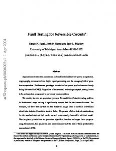
A reversible circuit has n inputs and n outputs, and maps each input pattern to a unique output pattern, i.e., it computes a bijective function. A k-CNOT gate has k control inputs c1 , . . . ck and one target input t. It maps the vector (c1 , . . . , ck , t) to the vector (c1 , . . . , ck , t⊕(c1 ·c2 · · · ck )). The values at the control inputs are left unchanged, and the value on the target input is inverted if and only if all the values at the control inputs are 1. A 1-CNOT gate is often just called a CNOT gate, and a 2-CNOT gate is called a Toffoli gate. Figure 2 shows a small reversible circuit composed of three k-CNOT gates. It has four “wires” representing the signals (qubits) being processed. The three CNOT gates process the four signals from left to right. Following standard convention, control inputs are shown as black dots, and the target input is denoted by a ringsum. The figure shows how input vector (1010) is mapped to (1100). Since all its gates are reversible, each group of gates in a reversible circuit is also reversible. Hence, any arbitrary state can be justified on each gate. For example, if the values (1111) must be applied to the rightmost 3-CNOT gate of Figure 2 for test purposes, there is a unique input vector that is easily obtained by backward simulation (1101 in this case). Furthermore, propagation of a fault effect is trivial: if a logic 1 value is replaced by a logic 0 (or vice versa) due to a fault, this will result in a different value at the output of the circuit.
2.2
Trapped-Ion Technology
Nielsen and Chuang [3] cite four abilities of a technology as necessary for quantum computation. The technology must: (1) robustly represent quantum information; (2) perform a universal set of unitary transformations; (3) prepare accurate initial states; and (4) measure the output results. In the following, we will briefly review how these
a 1
1
a 1
b 0
1
b 0
c 1
1
c 1
1
d 0
a
a
1
1
b
0
c
d 0
d
1
b 0
1
1
c 1
1
0
1
1
1
b 0
1
1
1
c 1
1
0
0
0
0
d 0
1
1/0
1/0
1/0
1
0/1
0/1
0
0
1
0
1
0
a
b
c
d
Figure 4: Single missing-gate fault (SMGF) and its physical justification
d 0
a
0
1
1
1
1
0
a
b
c
1
1
0
a
b
c
0
d
0
0
d
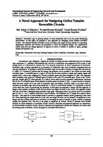
Figure 3: Physical implementation of the circuit from Figure 2 in trapped-ion technology four issues are addressed in the trapped-ion technology; see [3, 5] for further details. Qubit representation: The internal state of an ion serves as the qubit representation; the ground state (|gi) represents |0i, while the excited state (|e0 i) represents |1i. In trapped-ion technology, ions are confined in an ion trap, i.e. between electrodes, some of which are grounded (have a static potential) while others are driven by a fast oscillating voltage. The Los Alamos group used the Ca+ ions with 42 S1/2 as the ground state and 32 D5/2 as the excited state [12]. Unitary transformations: These operations rotate state vectors without changing their length, which implies reversibility. In the trapped-ion technology, ions interact with laser pulses of certain duration and frequency. Qubits interact via a shared phonon (quantum of vibrational energy) state. CNOT functionality has been experimentally demonstrated for the trapped-ion technology (as well as for NMR technology) [13]. Initialization: Trapped ions are brought into their motional ground state |00 . . . 0i using Doppler and sideband cooling. Measurement: The state of a single ion is determined by exciting an ion via a laser pulse and measuring the resulting fluorescence. Figure 3 illustrates the gate implementation in trappedion technology required for the circuit in Figure 2. The circuit has four wires a, b, c and d, so four ions (qubits) are used. Since the input vector is (1010), the qubits a and c are set to the state |1i and the qubits b and d are set to |0i in the beginning. The leftmost (2-CNOT) gate
is implemented by a laser pulse (or a sequence thereof) applied to qubits a, b and c. Their interaction results in the state of qubit b being changed from |0i to |1i. This is shown in the upper right of Figure 3. Similarly, the second (1-CNOT) gate corresponds to a pulse that changes the state of qubit c from |1i to |0i. The third gate does not result in a state change on the target qubit d due to a logic0 value at one of its control inputs (c); consequently, the third pulse does not change the state of qubit d.
3 Fault Models Next we introduce several fault models that are mainly motivated by the ion-trap quantum computing technologies discussed in the preceding section. The basic assumptions are that qubits are represented by the ion state, gates correspond to external pulses which control the interactions of the qubits, and the gate operations are errorprone. The fault models proposed are the single missinggate fault (SMGF), the repeated-gate fault (RGF), the multiple missing gate fault (MMGF) and the partial missing-gate fault (PMGF) models.
3.1
Single Missing-Gate Fault Model
A single missing-gate fault (SMGF) corresponds to the missing-gate fault discussed in [9]. It is defined as a complete disappearance of one CNOT gate from the circuit. The physical justification for a SMGF is that the pulse(s) implementing the gate operation is (are) short, missing, misaligned or mistuned. Figure 4 shows the circuit from Figure 2 with an SMGF: the first (2-CNOT) gate is missing. The resulting changes in logical values are shown in the format “faultfree value/faulty value”. It can be seen that the fault effect is observable on wires b and c. The right part of Figure 4 suggests how the pulse corresponding to the first gate is too weak to change the value on qubit b from |0i to |1i. The detection condition for an MGF is that a logic 1 value be applied to all the control inputs of the gate in question; the values on the target input as well as the values on the wires not connected to the gate are arbitrary. The number of possible SMGFs is equal to the number of gates in the circuit. The following characterization of SMGFs in proven in [9].
a 1
1
1
1
0
1
1/0
1/0
1/0
1
1
1
0/1
0/1
0
0
b c d
1
0
a
0 0
1
b
1
0
c
d
Figure 5: Repeated-gate fault (RGF) and its physical justification Theorem 1 (Properties of SMGFs) Consider a reversible circuit consisting of N CNOT gates. 1. There is always a complete SMGF test set of dN/2e or fewer vectors. 2. There are circuits for which the minimal complete SMGF test set has exactly dN/2e vectors. 3. By adding one extra wire and several 1-CNOT gates, every circuit can be transformed such that the resulting circuit retains its original functionality but has a complete SMGF test set consisting of one test vector. The transformation can be done for any test vector, but there is a unique test vector leading to minimal overhead (number of required extra 1-CNOT gates). SMGFs corresponding to the added gates are also covered by that test vector.
3.2
Repeated-Gate Fault Model
A repeated-gate fault (RGF) is an unwanted replacement of a CNOT gate by several instances of the same gate. The physical justification for an RGF is the occurrence of long or duplicated pulses. Figure 5 (left) shows the circuit from Figure 2 with a duplicated first gate. It can be seen that the fault effect is identical to that of the SMGF (Figure 4). Figure 5 (right) illustrates the double transition on qubit b first from |0i to 1|i, and then back to |0i due to a long or duplicated pulse. As a generalization, the following theorem holds: Theorem 2 (Properties of RGFs) Consider an RGF that replaces a gate by k instances of the same gate. 1. If k is even, the effect of the RGF is identical to the effect of the SMGF with respect to the same gate. 2. If k is odd, the fault is redundant, i.e., it does not change the function of the circuit. Proof: It suffices to see that two identical gates in series compute the identity function. Since the control and the target inputs of both gates are located on the same wire, the only wire whose value can be changed is the wire t on which the target inputs of the gates are placed. In Figure
a 1 b 0
1
1
0
1/0
1/0
1
c 1 d 0
0/1
0/1
1
0
X
0
Figure 6: Multiple missing-gate fault (MMGF), and a circuit fragment for which the optimal MMGF test set is larger than any SMGF test set 5, t corresponds to wire b. For a test vector that applies a logic-0 value to at least one control input of the first gate, the same holds for the second gate, and the value on wire t is unchanged by either gate. Otherwise, the value on wire t is inverted by both gates, and so ends up unchanged. 2 Theorem 2 is also an immediate consequence of a kCNOT gate’s unitarity property. From this theorem we conclude that an SMGF test set also detects all irredundant RGFs.
3.3
Multiple Missing-Gate Fault Model
This model assumes that gate operations are disturbed for several consecutive cycles, so that several consecutive gates are missing from a circuit. An example involving two missing gates is shown in Figure 6 (left). Note that the MMGF definition does not match our usual understanding of a multiple fault, which implies that several distinct single faults are present in the same time. We also restrict multiple faults to one or more consecutive gates. Hence for the circuit from Figure 6 (left), removing the middle and the rightmost gate yields a valid MMGF, but removing the leftmost and the rightmost gates does not. This fault model is justified by the assumption that the laser implementing gate operations is more likely to be disturbed for a period of time exceeding one gate operations than to be disturbed for a short time, then perform error-free, and then be disturbed again. Clearly, SMGFs are a subset of the MMGFs. In an N -gate circuit, the number of possible MMGFs is N (N + 1)/2, a quadratic function of N , whereas the corresponding number of multiple SMGFs is exponential in N . It has been proven for stuck-at faults in reversible circuits that a complete single fault test set covers all multiple faults [8]. This is not true for SMGFs and MMGFs, however, despite the restriction that the missing gates must be consecutive. This is demonstrated by the two-gate circuit fragment shown in Figure 6 (right). The SMGF corresponding to the left (3-CNOT) gate requires the test vector (111X) for detection, where X stands for “don’t care”. The SMGF for the second (2-CNOT) gate requires (X11X), so the optimal SMGF test set consists of one test vector, e.g., (1110). However, this vector does not detect the MMGF defined by removal of both gates, although it
a 1
1
1
b 0
1
1
1
c 1
1
0
0
0
0/1
d 0
1
1
0
a
b
c
0
1
d
Figure 7: Partial missing-gate fault (PMGF) and its physical justification is a complete SMGF test set. The MMGF is not redundant, as vector (011X) detects it. Furthermore, as every SMGF is also an MMGF, the vector (111X) also must be included in any complete MMGF test set. Hence, the optimal size of a complete MMGF test set is two. We have seen above that the size of the optimal test set for SMGFs is one. Hence, a complete SMGF test set does not cover all MMGFs.
3.4
Partial Missing-Gate Fault Model
A partial missing-gate fault is a result of partially misaligned or mistuned gate pulses. It turns a k-CNOT gate into a k 0 -CNOT gate, with k 0 < k. We call k − k 0 the order of a PMGF. Figure 7 shows a first-order PMGF affecting the third control input of the rightmost gate, and the weak pulse that fails to make c interact with a, b and d. An SMGF can be seen as a 0-order PMGF.
Circuit 2of5d1 2of5d2 3 17tc 4 49tc1 5mod5tc 6symd2 9symd2 ham3tc ham7tc hwb4tc hwb5tc hwb6tc hwb7tc mod5adders mod5d1 mod5d2 rd32 rd53d1 rd53d2 rd53rcmg rd73d2 rd84d1 xor5d1 Average
N 18 12 6 16 17 20 28 5 24 17 56 126 291 21 8 9 4 12 12 30 20 28 4
n 6 7 3 4 6 10 12 3 7 4 5 6 7 6 5 5 4 7 8 7 10 15 5
S M P 4 5 8 2 2 3 2 2 2 3 3 5 1 6 5 2 2 3 3 3 – 2 2 3 4 4 4 2 4 5 5 5 9 8 8 15 13 14 24 3 4 6 1 4 2 1 2 2 2 2 3 2 3 8 2 2 3 3 4 8 3 3 4 3 3 4 1 1 1 3.13 3.83 5.77
S+M+P 11 4 3 5 7 4 – 3 4 6 9 16 25 8 4 3 3 8 4 10 4 – 2 6.81
Table 1: Exact ATPG results (S = Single MGF, M = Multiple MGF, P = Partial MGF, S+M+P = all models combined)
Theorem 3 (Properties of PMGFs) 1. A k-CNOT requires k test vectors to detect all firstorder PMGFs and k + 1 vectors if the SMGFs must also be detected. 2. An m-order PMGF dominates m first-order PMGFs, i.e. it is detected by any test vector that detects one of the first-order PMGFs. Proof: 1. The detection condition for a first-order PMGF affecting the ith control input is to place 0 on the ith control input and 1 on all other control inputs, since this is the only case for which the fault-free and the faulty gate produce different values on the target node. Hence, different first-order PMGFs cannot be detected by the same test vector. Since there are k first-order PMGFs, k test vectors are required. To detect the SMGF affecting the same gate, we must place 1 on all control inputs. As this is incompatible with the detection conditions of any of the k first-order PMGFs, an additional vector is needed for SMGF detection. 2. A higher-order PMGF is detected when a 0 is applied to at least one of the affected control inputs and a 1 is applied to all other control inputs. Thus, any of the test vectors detecting a first-order PMGF affecting one of the
control inputs affected by the higher-order PMGF also detects the higher-order PMGF. Note that a test vector with a 0 on more than one control input may detect higher-order PMGFs but no first-order PMGFs. 2 The first result implies a lower bound on the number of test vectors for a circuit. It also implies that no circuit having a k-CNOT with k > 1 is testable for all PMGFs with just one test vector. This is different than the SMGFs case. It is possible to define PMGFs with respect to a target node. However, the resulting fault corresponds to a SMGF on the same gate.
4 Experimental Results We implemented an exact automatic test pattern generation (ATPG) method for the various types of MGFs based on integer linear programming. The number of test vectors is the objective function to be minimized, and the detection conditions are encoded as constraints. We applied this ATPG technique to the benchmark circuits in [14]. The first three columns of Table 1 give the circuit’s name, the number of gates N , and the number of wires n. The
computed number of test vectors for the single missinggate, multiple missing-gate, and partial missing-gate fault models are reported in the next three columns of the table. Dashes indicate circuits for which the ATPG procedure did not terminate within reasonable time. The final column contains the number of test vectors in a minimal set that detects all these faults. The bottom line of the table contains average values. Since repeated-gate faults (RGFs) are either identical to SMGFs or redundant, the values for the SMGF model are also valid for the RGF case. As mentioned above, the MMGF model applies to faults affecting consecutive gates and not to arbitrary multiple SMGFs. Since first-order PMGFs are dominated by higher-order PMGFs, our experiments only targeted first-order PMGFs, so the resulting test sets are complete with respect to arbitrary PMGFs. It can be seen that SMGF and MMGF test sets are of identical size in 14 out of 23 cases. However, there are circuits for which the test set sizes are considerably larger for MMGFs than for SMGFs. This confirms our statement that SMGFs are not dominated by MMGFs. Note that all of the results in the table are provably optimal. According to Theorem 3, a lower bound on the size of a complete PMGF test set is the maximum number of control inputs of any gate in the circuit. For the circuits considered, this bound is tight for circuits 3 17tc, mod5d1 and mod5d2, which consist of 1-CNOTs and 2CNOTs, and circuit xor5d1 which consists of 1-CNOTs only. Overall, the PMGF test sets are larger than SMGF test sets for all but three circuits, and they are almost twice as large on average. The test sets detecting all the faults (SMGF, MMGF and PMGF) are 18% larger than PMGF test sets, on average. This is consistent with the statement that a PMGF test is not a SMGF test for the same gate. Nevertheless, the test sets for PMGFs and the combination of all models are of identical size for seven circuits. This must be due to fortuitous detection of non-PMGFs by PMGF test vectors obtained for a different gate.
5 Conclusions Efficient testing and fault-tolerant design methods are required for realization and operation of quantum circuits. In this paper, we have considered the test generation problem for reversible k-CNOT circuits, which form a restricted class of quantum circuits, but capture some of their key characteristics such as lossless information processing and no cloning. Although conventional fault models for CMOS ICs have been applied to reversible circuits, their validity for quantum technologies appears to be quite limited. We have proposed a family of fault models for reversible circuits, based on the concepts of missing and repeated gate operations. These fault models are all defined at the logical level, which implies a high degree of technology independence and low computational com-
plexity. While applicable, in principle, to all known quantum technologies, they seem to be especially well-suited to trapped-ion technology (and spin technologies such as NMR). Issues for future research include modeling other types of gate defects, and dealing with the state superposition and measurement properties of general quantum circuits.
Acknowledgment John Hayes contributed to this work while visiting the University of Freiburg under an award from the Alexander von Humboldt Foundation.
6 References [1] C.H. Bennett. Notes on the history of reversible computation. IBM J. Res. and Develop., 32:16–23, 1988. [2] A. Peres. Reversible logic and quantum computers. Phys. Rev. A, 32(6):3266–3276, 12 1985. [3] M.A. Nielsen and I.L. Chuang. Quantum Computation and Quantum Information. Cambridge Univ. Press, 2000. [4] E. Rieffel. An introduction to quantum computing for non-physicists. ACM Computer Surveys, 32(3):300–335, 9 2000. [5] Quantum Computation (QC) Roadmap. http://qist.lanl.gov/, 2004. [6] E. Knill, R. Laflamme, A. Ashikhmin, H. Barnum, L. Viola, and W. H. Zurek. Introduction to quantum error correction. Los Alamos Science, 27:188–221, 2002. [7] K.M. Obenland and A.M. Despain. Impact of errors on a quantum computer architecture. Technical report, Univ. of Southern California, 1996. [8] K.N. Patel, J.P. Hayes, and I.L. Markov. Fault testing for reversible circuits. In VLSI Test Symp., pages 410–416, 2003. [9] J.P. Hayes, I. Polian, and B. Becker. Testing for missinggate faults in reversible circuits. In Asian Test Symp., pages 100–105, 2004. [10] J.I. Cirac and P. Zoller. Quantum computations with cold trapped ions. Phys. Rev. Lett., 74(20):4091–4094, 1995. [11] L. Steffen, L.M.K. Vandersypen, and I.L. Chuang. Toward quantum computation: a five-qubit quantum processor. IEEE Micro, 21(2):24–34, 3 2001. [12] R.J. Hughes, D.F.V. James, J.J. Gomez, M.S. Gulley, M.H. Holzscheiter, P.G. Kwiat, S.K. Lamoreaux, C.G. Peterson, V.D. Sandberg, M.M. Schauer, C.M. Simmons, C.E. Thorburn, D. Tupa, P.Z. Wang, and A.G. White. The Los Alamos trapped ion quantum computer experiment. Technical report, Los Alamos National Laboratory, 1997. LAUR-97-3301. Available from http://lib-www.lanl.gov/cgibin/getfile?00412906.pdf. [13] C. Monroe, D.M. Meekhof, B.E. King, W.M. Itano, and D.J. Wineland. Demonstration of a fundamental quantum logic gate. Phys. Rev. Lett., 75(25):4714–4717, 1995. [14] D. Maslov, G. Dueck, and N. Scott. Reversible Logic Synthesis Benchmarks Page. http://www.cs.uvic.ca/˜dmaslov/, 2004.