yInformation Technology Institute, National Computer Board, 71 Science Park Drive, ... zDepartment of Computer and Information Sciences, University of Florida, ...
A Fast Algorithm To Test Planar Topological Routability � Andrew Limy
Sartaj Sahniz
Venkat Thanvantrix
Technical Report 94-012
Abstract We develop a simple linear time algorithm to determine if a collection of two pin nets can be routed, topologically, in a plane (i.e. single layer). Experiments indicate that this algorithm is faster than the linear time algorithm of Marek-Sadowska and Tarng[1].
Keywords and Phrases
single layer topological routing
This research was supported in part by the National Science Foundation under the grant MIP 91-03379 Information Technology Institute, National Computer Board, 71 Science Park Drive, Singapore 0511, Republic of Singapore. z Department of Computer and Information Sciences, University of Florida, Gainesville, FL 32611, U.S.A. �
y
x
Department of Computer and Information Sciences, University of Florida, Gainesville, FL 32611, U.S.A.
. . . . . .. . . . . . . . ... .... . . . . . 1 .5....... ..... ... ... .... . . . . ..... ......... ... ... . . .. ... ... ... 12. . .. . . . . . .. . . ..... ... 5 .... .... . . ... 3.... ...... ........ 4 .... ..... ... .3 .4 .... .... ... . . 2 .... ... ...........................
...1 . . . . . 1... 2. 3 ..... .....
.5....
.... 5 R...... 4 6........... 6 ...
3 4
(a) Planar Routable
I
2
(b) A non planar routable example
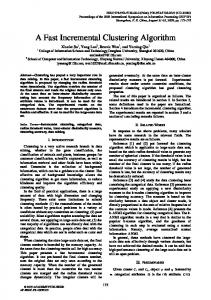
Figure 1: A planar routable and a non planar routable case
1 Introduction The problem of routing two pin nets on a single layer has been studied previous by several researchers. The river routing and switch box routing problems are special cases of this. E�cient algorithms for these can be found in [2, 3, 4, 5, 6, 7, 8, 9, 10, 11]. In this paper, we are concerned with the problem of routing (topologically) a collection of two pin nets in a single layer or plane. We refer to this problem as the TPR problem. The input to the problem is a two dimensional routing surface with a collection of modules placed in it (Figure 1(a)). There are pins on the periphery of the modules. Pins with the same number de ne a net and are to be joined by an interconnect or wire. In topological routing, we are concerned with de ning wire paths. However, no underlying grid is assumed and there is no minimum wire separation requirement. Thus wire paths can take any planar shape and may run arbitrarily close to each other. Wires are not permitted to intersect or run over modules. In Figure 1(a), the broken lines indicate wire paths. The routing instance (RI) of Figure 1(a) is topologically routable in a single layer while that of Figure 1(b) is not. The TPR problem for RIs in which all modules lie on the boundary of the routing region (or more precisely all pins are on the boundary of the region) was studied in [1, 2, 8]. A simple linear time algorithm for this version of the TPR problem was developed in these papers For the case in which none of the modules are on the boundary, Pinter [8] has suggested using the linear time planarity testing algorithm of Hopcroft and Tarjan [12]. His algorithm is quite complex. Marek-Sadowska and Tarng [1] have considered the TPR problem and several variants which include ippable modules and multiterminal nets. They develop a linear time algorithm for TPR which is based on module merging. In this paper, we develop 1
1
bt bt
2
ct 3
ct
4
(a) RI
A
at
at
1
gt
gt
C
tf
2
B
3 t
d
t
d
t
e
(b) Augmented RI
t
4
tf
e
Figure 2: Augmentation another linear time algorithm for the general TPR problem that is almost as simple as the one of [1, 2, 8] for the restricted TPR problem. Experimental results indicate that our algorithm is considerably faster than the TPR algorithm of [1] particularly if the routing instance is not planar routable.
2 Preliminaries To simplify matters, we shall assume that TPR RIs that have modules on the boundary (Figure 2(a)) have been augmented by a set of nets that are required to be routed on the boundary and that this routing together with the module boundaries enclose the routing region (Figure 2(b)). This augmentation may require the addition of corner modules (A; B; C of Figure 2(b)). This assumption is needed so that our algorithm can account for the constraint that one cannot route around a boundary module but can route around all other modules. A pin segment, P = p1p2 : : :pk , is a sequence of pins on the boundary of a module. p1 : : :pk appear in this order when the module is traversed counter-clockwise beginning at p1. Some of the pin segments of the modules of Figure 3 are: abcde and gjkH of module 1; MLK and LKJGf of module 3; and AiF of module 2. Let last(P ) and first(P ), respectively, denote the last and rst pins of segment P . Let net(pi ) denote the net associated with pin 2
........................................................... ................. ....................................... ............. ................ .......... ......... ....... ......... ..... .................................................. ....... . . . . . . . . . . . . . . . . . . . ............ ..... ....... ..... . . ..... . . . . . . . . ....... . ..... .... . . . . . . . . . . . . .... ..... . ... . . . . . . . . . . . . . . . . . . ..... ... .............. ............................ . . .... . . . . . . . .... ......... ... ... . . . . . . . . . . . . . ... . . . . . . . . ..................... .... ... ................ . ..... . . .... ... ........... .. . .. . . . . . . . ..... ... .. .. . .. . . . ... . . . . . . ... . . . .. ... ... .. .. .. .... . .. .. . . . . . . . . . .. .. ... . . .. . .. .. ... . . . . . . . . . . . .. . .. .. ... . . . . .... . .. . . . . . . . . . . .. . .. .. .. .. .. . . . . . . .... . . . . . . . . . . . .. . . .. .. . .. .. . . . . . . . . . . . . . . . .. . . .. . . .. ... . . . .. . .. . .. . ... .... . .. . . . . . . ... ... .... .. . . .. . . ... ....... .. ... .. . . . .. . .. . . . . . ... .. .. . . . . . . . . . . . . . .. .. .. .. .. .. .. . . .... . ... . . ... .......... .. . .. . ............. ... . ... .. .. . ... . ... ... .... .. . .. . ... ... . .... .. . . ... ............... . . . . . . . . .. ..... .... .. .. .. ... .... ... .... ..... .. ... ... ..... ... ... ... .... .. ... ... ...... .. .. ... .. ... ....... .. . . .. ... ... ... ... .. .... ... . . . .. ... ..... ... ... . . ... ....... .. . . .. ... .. ..... . . . . . . ...... ... . . . . . . . . . . . ... .. ..... ... .. ... ....... . . . . . . . .. .... . . . ...... ... . . . . .... .. ........... ...... ... .. ...... . . . . . ... . . . . . . . . . . . . . . . . . . . .. . . . . . . . ..................... ......... ........ ... .. ... .................................... . ......... . . .... . . .......... . ... .... . . . ........... . . . .... . .............. ..... .... ... ............... ........ ..... ... .................... ......... ..... .... ...................... ............ .... .... ........................... ............... ....... ..... ............................... ................. . . . . ......... . . . . . . . . . . . . . . . . . . . ............................................................................... .......... .... ............. ............ ................... ................ ............................ ............................ .................................................. ................................. ....................................................................................................................................
Ha kb c 1 d j e g
h
G
l 4
m I
iA B C2 D EF
J K 3 L f M
Figure 3: An example to illustrate some terminology
pi . Note that two pins pi and pj are to be connected by a wire i� net(pi ) = net(pj ). A curve, C = P1P2 : : :Pj , is a sequence of pin segments such that net(last(Pi )) = net(first(Pi+1 )), 1 � i < j . A curve, C = P1P2 : : :Pj , is a closed curve i� net(last(Pj )) = net(first(P1 )). In Figure 3, net(pi ) is the lowercase letter corresponding to pi . So, net(h) = net(H ) = h. Some of the curves of Figure 3 are Ih Habcdeg Gf FEDCBAi, j JGfM mIh, edcba ABCDE and ABC cdeg GfM . IhHabcdeg Gf FEDCBAi and edcba ABCDE are closed curves. With any curve C = P1 P2 : : :Pj , we associate j ? 1 (j in case C is closed) wires. These, respectively, connect the pins last(Pi ) and first(Pi+1 ), 1 � i < j (and last(Pj ) and first(P1) in case of a closed curve). Note that the curves, closed curves, and wires associated with any RI depend only on the modules and the net to pin assignments. These are not a function of the layout of any of the wires. For any closed curve C = P1 P2 : : :Pj we de ne the following:
module(Pi) pins(module(Pi)) pins(Pi) pins(C ) ext pins(C )
::: ::: ::: ::: :::
module corresponding to pin segment Pi set of all pins on module module(Pi) set of all pins on segment Pi S set of all pins on curve C = ji=1 pins(Pi ) Sj pins(module(P )) ? pins(C ) i i=1 3
............................. ...... ... .. ... ..... ..... ..... ..... .... ... . ..... ..................... .....
A a
........ .... ...... .. .. ... .. ........ ... .. ....... ...... .. .. .... ... .... ...... .. . . . ... ..... .. .... ....
E
. ... ....... .................. ........ .. ... ... .... ... .... ........................
D
.. ............................. . ...... . ... . ..... ..... ..... ...... ..... .. ... ................ ........... . .
B b
...... ........ ... .... ........... . . . . . . . . . . ......... .. ...... .....
E
. .. ... . ................ ............ . .. .... ... .. .. . ... ............... ............
C
.... .... ... ..... .. ... . ... .. ... .. .... .... . . ..... . . . . .............................
(a) Original Situation
.................................... ......... ....... .... .... ... ...... .... .... .............. . .. . .................... ....... . ... .. .. . . .. .. . .. .. ... ... . . ... .. ... . . . . ... . . ... .... . . ........ ...... ....... ..... ....... .. ... ......... . . . . . . . . . . . . . .. .... .. .. ..... ......
A a
D
B b C
.... .... ... .... .. .... .... ... ... ... .... .... . ...... . . . . . . ..........................
(b) Connect terminals a and b
........................................................... .................... .. . ........... .. ........ ........ ..... .......................... ... ...... ........... . ....... .... . ... . ............................ ..... .. .... .. .... .... . ........ . . . . . . . ..... . . .... ... ........ ... . ..... . . . ..... . . . . . ... . . . . ..... . . .. .... ... . .. . .... ...... . . . . . ................ .. .... .. ... . . . . . .. . ... .. .. .. ... .. .. .. . . ... . . . . . . .. ...... ....... ...... .............. ... . ... . .. . . .. .. . . . .. . ...... . . . . . .. . . . . .. . . . . . . . . . .. ....... .. . .. ...... .. ... .. ..... .. .. . ... . .. . .. .... . . .. ........... . ............... .. .. . . . .. ... .. .. . . . .. . .. ... .. . . . . ... . .... . .. . .. . ... . . . . ... . ... .. ..... .. .... ...... ... . .... . .... ..... ....................... .... .. ..... ..... ... .. ...... ......... .... .... ............ .................... . . . . . . . . . . .. ....................... .. .... .......................... ....................................................... ..............................
A a
B b
E
C
D
(c) Re-routing of some net
Figure 4: Two possibilities to connect a and b Note, it is possible that module(Pi) = module(Pj ), for i 6= j .
Lemma 1 : Let I be an RI that contains a closed curve C with respect to which there are two pins a 2 pins(C ) and b 2 ext pins(C ) such that net(a) = net(b). I is not planar routable.
Proof : Figure 4 shows two possibilities. It should be clear that no matter how the wires
of C and the wire (a; b) are laid out, there must be an intersection between two of these.
2
Lemma 2 : Let I be an RI that contains a closed curve C = P1; P2; : : :; Pj and another curve R = R1R2 : : :Rk such that module(R1) = module(Pd ) for some d, 1 � d � j and first(R1) 2 ext pins(C ) (see Figure 5). Assume that there exist two pins a and b such that a 2 pins(C ), b 2 ext pins(C ) S pins(R), and net(a) = net(b). I is not planar routable. Proof : Follows from Lemma 1. 2 4
........................... ........ .... ...... .... ... ... .... .... ...... ....... ...... ..... ... ... ... .................... . . . . . . . . . . . . . . ....
A a
......... .... ....... ... .. ... . .. ... ...... ... ... . ......... ......... .. .. ... ...... . .. .... .. . . ... . . . ... . . . . . . . .. . . . . ... .... . ....
..... .... . . .. . . .. .. .. . . . . .. .... . ........... . . . ...... ...... .. ... ..... .... .. .... . .... ... ... . .. ....... . ... . . . . ... ...... .. . . . . . . . . . . .... ...............
....... ....... ..... ... ..... ............. . . . . . . . . . . . . . . . . . . . . . .. .. .. ...... ..... ...
E
... ... ...... .................. ............ .. . .... ... ... .. . . .... ....... .........................
B
F
G b
C
D
.... .... .... ... .... .. .... . .... .. .. .... .... ... . . . .... ..... . . ....... . . . . . ...................................
Figure 5: Another not planar routable situation Two modules are connected i� there is a curve C = P1 P2 : : :Pj such that both modules S are in ji=1 module(Pi). A connected component (or simply component) is a maximal set of modules that are pairwise connected. It is easy to see that the connected components of an RI are disjoint. A boundary component is a connected component that includes at least one boundary module. Note that an RI with no boundary modules has no boundary component while an RI with at least one boundary module has exactly one boundary component (this is because RIs with boundary components have been augmented as in Figure 2(b)).
Lemma 3 : An RI is topologically routable i� its components are (independently) topolog-
ically routable.
Proof : It is easy to see that if the RI is topologically routable then each of its components
is topologically routable. Assume that each component is toplogically routable. Order the components of the RI so that the boundary component is rst. The remaining components are in arbitrary order. Let the components in this order be K1 ; K2; : : :; Kk . If k = 1, then nothing is to be proved. So, assume K > 1. We shall show how to construct a topological routing for K1; K2 : : :; Ka from a topological routing for K1; : : :; Ka?1 and Ka, 2 � a � k. First since a > 1, Ka is not a boundary component. So, it is possible to surround it by a closed non self intersecting line such that the region enclosed by this line includes exactly those modules that are in Ka and no module touches the line. The region enclosed by this closed line has the property that any two points in the enclosed region can be joined 5
...................... .... .. .... .. ... ..... ....... ...........
.................... .... .. ... .. ... . ..... ...... .............
.................. ... .... ... ... .. .. .... ..................
...... ....... ...... ...... ....... ....... . . . . . ...... ...... ...... .......
............ ..... ...... .. ... . . ... .. .... .....................
...... ....... ....... .....
............... ..... .. .. .. . . . ... .... ... ....................
....... ....... ...... ..... ...... ... ....... ........ . .. . . ... .. . . ... . ... .. ... .... . . ... ..................
...... ...... ........ ... .. ... .. ... ..... ....... .........
... ... ... ... .... ..................... .... ... ... . . . .. . ... ... .. .... .... . .................... . ........ ....... ....... ...... ....... ...... .......
.......... ...... ....... ... . . . .. .. . ... ..... ........ ..........
(b) Spanning tree
(a) Module 2 Ka Module 62 Ka ...... ..... ..... .......
............ ..... ...... .. . . .. ... .... ... ..................
......................... ....... .... ........................... ..... ... ... ............... ... .... ... ......... ... ...... . .. . . . . . . . . . . .. ... . . . . . . . .. . . . . ..... .. . . . . . . . . . .. .. ..... . . . . . . . . . . . .. ..... ... .. . . . . . . . . . . . . . .... ...... ... ... ........... .... ....... .. ..... ... ...... ....... .... . .... ........... ... ...... .... .. ............................... .... ... .... . .. .... .. ... . . . . . ... . . .. . . .... ..... ... .. .. .... ........ .. . . ..... .............. ... . . ..... ................................... . ... ... ...... ....... .... . . . .... . .......... .. .... ........................ .... ... .... ............... .... .. ...... . . . . . . . ....... ....... ....... . ....... .. ........... ....... ..................... ....... ..... .. . . .......... . .... . . . ....... ..... .. . ... . . . . . . . . ... ............ .......... .. ............. .. . .. . . .. ... ... .... ... ...... ... .......... .... ........................................
(c) Envelope
Figure 6: Constructing the envelope of a component
. . . . . . . . ............ . .......... ............. ................................. . ...... ... ............ ... ..... . ... ... ......... . . .... . . .. . . . ... . ... . . . . . . . . . . . . . . . .... . .. . . . . . . . ... . . .... .. . . . . . . . . . . . .. . .... . . . . . . . . . . . . . . . . ... .. ...... . . . . . . . . . . . . . . . .. . ...... ... .... . .... ....... ... .................... ... ....... . ....... . ..... .. .... . .......... .... ........... ..... .. .. ............................. . ... ... ....... ... . . ... . . . . ... . .. .. . ... .. .... .. . . . ... . . . ..... .......... . ....... . . . . . . . . . . . . . . . . . . .................................... ...... . ... .. . . ........ . . . . . . . ......... ... . .. . ..... . ................ .. ... . ...................... .. .... . ....... . . .. . . . . . . .......... ...... . . ........ ........ ........ .. . .. ...... . ........... ............... . ... ....... ...................... . . ...... ... . ...... ....... . .. . . .... . . . ...... ..... ... . . ... . . . . . . . . . . . . . . . ....... ....... ... . . . . . . . . ... . . . . . ................ . . .. . . . ... . .. . . . ....... .. . ...... ... . . . . . . . . . .. . .. . . . .......................... .................... .. . . . . ............ . . .. . . . . . .
. . ............ . .................................. .......... ............. .. ...... ... .... . . ..... . ....... .......... ... .... ....... .. ... . . ..... . ... . . . . . . . . . . .. . . . .... . .. . . . . . . . .. ... .. .... . . . . . . . . . . . . .. . ... ... . ........... . . . . . ......... ... .. . . . . . . . . . . . .. .. . ....... . . .... ... .... ....... ................... ... ....... .... ........ . ......... .. .... .... ........... ..... ...... .. .. ............................. .... . ... ... . .... ... . . . . . . . ... .. ..... . .... .... . ... ... . .. .... . . ......... .... ... .. ....... .... ... ... . ............................................. ....... .... ... ........ ..... . .... .. .............. .. .... .... . ....................... .. ... .... . . . . . . .. . . . . .......... ...... ..... . ........ ....... ......... . . . . . .. ...... . ...... . ... ....... ...... . . . . ................................... ... ...... ........ . . . . . . . . . .. ...... ..... . .... . ... . . . . ......... . ... . . . . ....................... .. .. .. .. ... .. .... .. ...... ... . . . ....... . . .............. ....... ...............................
(a) Intersections
(b) Re-routing to remove intersections
Figure 7: Re-routing to free independent component
6
by a line (not necessarily straight) that lies wholly within the region. We refer to the surrounding line as the envelope of Ka . One way to obtain an envelope of Ka is to rst construct a set of jKaj ? 1 (jKaj is the number of modules in Ka ) lines (not necessarily straight) so that modules of Ka together with these lines form a connected component in the graph theoretic sense (see Figure 6). These lines do not touch or cross any of the modules of RI. This construction can be done as every pair of modules of an RI can be can be connected by such a line. The lines and modules de ne a spanning tree for Ka . By fattening the lines as in Figure 6(c), the envelope is obtained. It is easy to see that if Ka is topologically routable, then it is topologically routable with the de ned envelope. So, use such a topological routing for Ka. When this routing is embedded into the routing for K1 ; : : :; Ka?1 some of the topologically routed wires of K1; : : :; Ka?1 may intersect (or touch) the envelope of Ka . However, none of these wires originate or terminate in the envelope of Ka. So, these can be rerouted following the contour of the envelope (Figure 7).
2
As a result of Lemma 3, we need concern ourselves only with the case when the RI has a single component.
3 The Algorithm Our algorithm to obtain a topological routing of a component uses Lemmas 1 and 2 to detect infeasibility. The algorithm is given in Figure 8. As stated, it only produces an ordering of the wires such that when the wires are topologically routed, one at a time, in this order, then there is always a path between the two end points of the wire currently being routed such that this path does not intersect previously routed wires or cross any of the modules. This is su�cient to obtain the actual topological routing. Our algorithm employs two stacks A and B . Stack A maintains a pin sequence that de nes a curve of the RI . Stack B is used to retain pins that de ne closed curves with respect to a (sub) curve on stack A. We describe the working of the algorithm with the aid of an example (Figure 9(a)). There are four modules 1 ? 4 and 16 pins a ? h and A ? H . net(p) = p if p is a lowercase letter and net(p) = lowercase(p) if p is an uppercase letter. Suppose we begin in step 1 with m = 3 and p = B . Then in step 2, BAFEC get stacked, in that order on to stack A. This corresponds to the curve of Figure 10(a). In step 4 the curve is extended to module 1 by adding pins cefgD. The stack contains BAFEefgD and the curve traced so far is shown in Figure 10(b). The wire Cc is output for routing. The 7
Algorithm Testing Planar Routability Step 1: Let m be any module of the component and let p be any pin of m. Step 2: Examine the pins of m in counterclockwise order beginning at pin p. When a pin q is being examined compare net(q) and net(r) where r is the pin (if any) at the top of stack A. If stack A is empty or net(q ) 6= net(r) then add q and the remaining pins of m to the top of stack A. Otherwise output (q; r) and unstack r from A. Step 3: If both stack A and B are empty, then terminate. Step 4: Let r be the pin at the top of stack A. Let s be the pin such that net(r) = net(s). (a) If s is at the top of the stack B , then [output (r; s); unstack r from A and s from B ; goto start of Step 3]. (b) If s is in stack B but not at the top, then [output(\The RI is not planar routable"). Terminate]. (c) If s is in stack A, then [unstack r from A; add r to stack B ; go to the start of Step 4]. (d) If s is in neither of the stacks then [ set p to s; let m be the module containing s; goto Step 2]. Figure 8: Topological routing.
8
gfe 1 Dc h2
............................................................................................................................................................................................................. .. ............ .................. ....... ....... .................... ............ ........ .............................. ....... ....... .... .... ....................................................... ........... ...... ..... ........ ....... ..... .. .. ..... ... . ..... . ..... ... ... . .... ... .. . . .. . . . . . . . ... . .... ... .... .. .... . . . . . .. . .. . . ... . . .. . . . ... . . . . .. .. . . . . .. . . . . .. .. ... . . .. . . . . .. . .. .... . .. . . . .. . . . .. .... . . . . . . . . . . . . ... ... . . . . . . . . . . . . . . ... . . ... . . . . . . . . . . . . . . . . . .. .... .... . . . . . . . . . . . . . . . . . .. . ...... . . . . . . . . . . . . . .. .. . ............... .. ... . . . . . . . . . . . . . . . . . . . . . . . . . . . . . . . . . .. . . ...... . . .. . . . . ... . . . . .. . .................. .. . ... .. . . . . . .. .. .. .. .... .... . . . ... ... .... ... ... ....... ... .. ...................................... . . . .. .............. .................... .. ... .... ...... .......... ... ..... .. .... ..... ........ ..... .. ... .. .... ....... ............ ........................... . . . . .. .... ..... ...... . .............. . ... ..... .... .. . ......... . . . ... ..... ... . . . .... ... . ... ... ..... .... .. .. . .. .. . ... .. . . . . . . .. . . . .. . .. .. .. . . . . ... .... ... . . . . . .. .. ... .... ... . . . . . . . . .. . . ...... ..... .... . . ... . .. .... .... . ....... ... . ... ............... ................ .......... ..... ........... ................. ............ ...... ............................................. ....................................................... .....................
gfe 1 Dc
G a4 H
d b
h2
AB C 3 FE
G a4 H
d b
AB C 3 FE
(a)Example RI
(b)A possible topological routing
Figure 9: Example RI
B -A-F -E -C
B -A-F -E -C - c - e - f - g -D ...... ...... .........
(a)
(b)
B-A-F -E -C - c - e - f - g -D- d - h - b H-G- a (d)
B - A-F -E -C - c - e - f - g -D- d - h - b ...... ..... ............
...... ...... .........
..... ..... ...........
(c)
B - A-F -E -C - c - e - f - g -D- d - h - b H-G- a ...... ...... ...........
(e)
...... ...... ..... ........... .... ..... ...
B- A-F -E-C - c - e - f - g -D- d - h - b H-G- a
...... ...... ...... ... ......... ... .. ..... ... ... ... ..... ....... ....... ............. ...... ...............................................
...... ...... .... . ......... ... .... .... ... ...... .... ........... ............... ..............
(f)
Figure 10: Illustration of the routing sequence
9
...... ...... ..... . . . ........... .... ... ..... ... ... .... ..... ..... ....... ......... ..... .....................................................
gfe 1D c
......... ........... ................... .... . . . ........ .... ... . ..... . ... . . . . .... . . . . . . . . . . . . . . . . . . . . . . . . . . . . . . ........ . ........... .... . .. . ........ . . ..... . ... . . ..... . . ... . . . . . . . . . . ...... . . . . ......... . ...... . ............ . . ..... . . . . . . . . . . . . . . . . . ... .................... . . . ............... . . ... .... ..... . ... ............ .................................... . . . .. .. . . ........... . . .. ... ... ......... . . . ............ . .. .... . ........ . . . . . . . . . . .. ..... . . .......................................... . .. . . . . ... .... . . ... . . . . . . . . . . . . ... . . . ... ....... . . . ... . .... . . . . . .. . .... . . . .. . . . . . . . ... . . ... . . . ... ... . . .. . .. . . ..... ... ... ............ . . . . .. . ... . .... . .. . ... . . .. . . . .. . .... . .... ... .... ... . ... . . .. ... ..... ...... . . . . . . . . . . . . . . . . . . . . . . . . . . . . . . . . . . . . ... ...... . . . . . . . . .................................. . .. . . . ....... .... ........................... . ... ..... . . ... . .............. . ... . . . ...... . .... . ........ . . . . .... . ...... ..... . . .............. ....... .............................
h2
d b
G a4 H
AB C 3F E
Figure 11: Trapped terminal and module routed wire wire Cc is shown as a curve. The curve is extended to module 2 and stack A has the con guration BAFEefghb. The wire dD is output for routing. The curve now has the form given in Figure 10(c). The curve cannot be extended further as both end points of wire Bb are on the stack. This means that we have detected a closed curve of the RI. The detected closed curve is that of Figure 10(c). We defer the routing of Bb until we have veri ed Lemma 1 and 2 for this closed curve. This deferment also ensures that the current topological routing does not contain a closed line. If Bb were routed now, then the wires Bb, Cc, and Dd together with the boundaries of modules 1, 2, and 3 would de ne a closed line that encloses a non-empty region. This could result in future routing problems as there would be no path between a point in the region and one that is outside the region. For example, if the routing of Figure 11 is used, then there is no path between a and A as a is in the enclosed (shaded) region while A is outside of it. The routing of Bb is deferred by saving b on stack B . The curve of stack A is extended to module 4 via the wire hH . Wire hH is output for routing. Stack A now contains BAFEefgGa. The curves traced so far and the routed wires are shown in Figure 10(d). Another closed curve is identi ed by stack A (AFEefgGa). The routing of Aa is deferred by adding a to stack B to get a stack B con guration of ba. Next the routing of gG is deferred and we get the stack B con guration baG. Since g is at the top of stack A and G is at the top of stack B we know that all wires on the curve segment from g to G have been routed. Routing gG at this time will create an enclosed region with the property that all pins within the region have been routed to. 10
s
s
.. ..... .... .... ... .... .. .. ... ... ... ... . .. . . . . . . . . . . . . . .. .. .. ... ... ... .... .... .... .... .... .... ..... ... ..... . ...... ... ...... ................. ............ .................................
... ...... .. .... ...... . . .. . .. ... ..... ...... ....... ....
uv m .. ... . .. . . . . . . . . ..
r t
y
.................... .. . . ........ . . . . . . . .. . .. . ... ...................
.............................................. ..... .... ... ... .. . . .. . ... . . ... . . . ................. .... .................. . . . ........... ............ ......... ..... . ...... . . . ..... . ....... . . .......... . . . ............. . .. . . .
y
x
r t
. . . . . . . . . . . . . .. . ... .. .... . . .... .. ........ ................ .. ....................................
.............................................. ...... .... ... .. .. .. . . .. .. . ... . . . ................. .... . ................... . . . . . . .. ............ . ......... ........ . ...... .. ..... ....... ... . . . ........... . ............ . .. . . .
(a)
(b)
Figure 12: To illustrate con ict Wire gG is output for routing. This gives the con guration of Figure 10(e). Stack A has BAFEef on it while stack B has ba. f is moved to stack B as its routing would enclose a new region and Ee is routed to get Figure 10(f). Ff , Aa, and Bb are then output for routing in that order. The routing order is Cc; Dd; Hh; Gg; Ee; Ff; Aa; Bb. Let us try this out on our exmaple. We see that no matter how Cc is routed there will remain a routing path for the remaining wires. The routing of Dd and Hh cannot create any enclosed regions and so cannot a�ect the feasibility of future routes. When Gg is routed, an enclosed region bounded by the wires Cc; Dd; Hh, and Gg is created. When routing Gg we need to exercise care that the enclosed region contain no pins to which a wire has not yet been routed. This can always be done as before the routing of Gg there is a routing path between all pairs of points. Wires Ee; Ff; Aa, and Bb are routed succesively. The topologically routed RI can be found in Figure 9(b).
Theorem 1 : The algorithm Testing Planar Routability (given in Figure 8) is correct. Proof : It is easy to see that if the algorithm terminates in step 3 the wires are planar
routable. If the algorithm terminates in step 4(b), then let r and s be as in step 4. r is 11
at the top of stack A and s is in stack B but not at the top. Let x be at the top of stack B and let y be the pin such that net(y) = net(x). y must currently be on stack A as x can be put on stack B (see step 4(c)) only if y is on stack A. When one pin of a net is in stack A and the other in stack B , the pins can leave the stacks together (step 4(a)) or not at all. Since x is on stack B at termination, y must still be on stack A and hence must be lower than r (as r is at the top). So, there is a curve y : : :r in the RI. Furthermore, curves y : : :r : : :s and y : : :r : : :x must exist as this is the only way s and x can get to stack A and then to stack B . Figure 12(a) shows an example curve y : : :r : : :s. This gure assumes that module(s) 6= module(r). The proof for the case module(s) = module(r) is similar. Let m be the module at which the curves y : : :r : : :s and y : : :r : : :x diverge (Figure 12(b)). Note that m may be module(r) or a latermodule on the curve y : : :r : : :s. Let u be the pin of m that is the last pin of m on curve y : : :r : : :s and let v be the corresponding pin for y : : :r : : :x. Since all nets are two pin nets, u 6= v. Since x is above s in stack B, v must be on the curve y : : :r : : :s. The curve C = y : : :r : : :v : : :x is a closed curve. We see that r 2 pins(C ), and s 2 ext pins(C ), and net(s) = net(r). So, s and r satisfy the conditions of Lemma 2 and the RI is not planar routable. 2 The algorithm of Figure 8 is easily implemented to have complexity of O(n) where n is the total number of pins. For this we need to use an array status[1..n] to maintain the current status (i.e., on stack A, on stack B , on neither) of each pin.
4 Implementation While the correctness proof for our algorithm is somewhat involved, the algorithm itself is quite simple and easy to implement. To get good performance we implemented stack A as a stack of modules rather than one of pins as described in Section 3. So, when step 2 of Figure 8 adds q and the remaining pins of m to stack A, we simply add a record of the type (m; q; l) where l is the last pin of m to the stack. Also, to get the top pin of stack A, we look at the top record (m; q; l). The top pin is l. To delete this pin, the top record is changed to (m; q; p(l)) where p(l) is the predecessor of pin l unless q = l. In the latter case, the record (m; q; l) is deleted from the stack. The role of array status needs to be changed to support this change in stack structure. We now keep a status for a module as well as for a pin. A module's status re ects whether or not it is in stack A and a pin's status re ects whether or not it is in stack B . The algorithm of [1] is a two step algorithm: 12
Figure 13: Tree-like Connected Circuits Step 1:Merge modules together to obtain an equivalent routing problem in which all pins are on the periphery of a routing region. Step 2:Determine the feasibility of the equivalent problem using a single stack scheme. To implement step 1, we performed a traversal of the modules. Each module was represented as a singly linked circular list of pins. With this representation, modules can be merged e�ciently. By contrast, for the algorithm of Figure 8, modules were represented using doubly linked circular lists.
5 Experimental Results We implemented our algorithm and that of [1] in C and obtained execution times using both circuits that are routable and those that are not. The routable circuits used are highly structured ones as shown in Figures 13 and 14 as well as randomly generated ones. The nonroutable circuits used were obtained by modifying the tree-like circuits of Figure 13. The timing results for the routable circuits are shown in Tables 1, 2, and 3, respec13
Figure 14: Six-way Connected Circuits
NP 864 704 1440 6048 6944 24928 NM 16 25 49 100 225 400 Our 3.40 2.91 5.53 22.90 27.40 93.30 [1] 5.45 4.36 9.10 37.80 44.90 162.80 NP = Number of pins in the circuit NM = Number of modules in the circuit Table 1: Tree-like Connected Circuits NP 1792 1920 522 8352 9856 17396 NM 25 49 100 100 225 400 Our 8.48 10.17 4.20 44.54 53.60 105.40 [1] 11.08 11.93 9.52 55.18 66.25 121.90 Table 2: Six-Way Connected Circuits 14
NP 92 1472 2944 11776 NM 28 28 28 28 Our 0.91 6.54 12.76 49.95 [1] 0.98 9.18 18.17 78.20 Table 3: Random Circuit NP 868 6944 13888 NM 25 225 225 Our 3.70 16.24 30.30 [1] 15.50 45.70 92.50 Table 4: Faster Termination for NonRoutable Circuits tively. The times are in milliseconds and the programs were run on a SUN 4 workstation. on tree-like circuits, the algorithm of [1] took 65% more time than ours, on average; on six-way circuits, it took approximately 40% more time; and on random circuits, it took approximately 37% more time. Our algorithm has a distinct advantage over that of [1] when working with nonroutable circuits. The algorithm of [1] must complete its step 1 before it can detect infeasibility, whereas our algorithm can detect infeasibility at any stage. Hence, it is possible for our algorithm to take much less time than that of [1] when working on such circuits. The results from three test circuits is given in Table 4. The algorithm of [1] took approximately 3 to 5 times as much time as did ours.
6 Conclusion We have developed a relatively simple and fast linear time algorithm to test the planar topological routability of a collection of two pin nets. The algorithm is faster than the linear time algorithm of [1].
15
References [1] M. Marek-Sadowska and T. Tarng, \Single-Layer Routing for VLSI: Analysis and Algorithms," IEEE transactions on Computer-Aided Design, vol. CAD-2, no. 4, 1983. [2] C. Hsu, \General River Routing Algorithm," in ACM/IEEE Design Automation Conference, pp. 578{583, 1983. [3] C. Leiserson and R. Pinter, \Optimal placement for river routing," SIAM Journal on Computing, no. 12, pp. 447{462, 1983. [4] A. Lim, S. Cheng, and S. Sahni, \Optimal Joining of Compacted Cells," IEEE Transactions on Computer, accepted in 1991. Extended abstract in 1992 Brown/MIT Advanced Research in VLSI and Parallel Systems. [5] A. Mirzaian, \River Routing in VLSI," Journal of Computer and System Sciences, no. 34, pp. 43{54, 1987. [6] A. Mirzaian, \A Minimum Separation Algorithm for River Routing with Bounded Number of Jogs," in International Conference in Computer-Aided Design, pp. 10{13, 1989. [7] R. Pinter, \On routing two point nets across a channel," in ACM/IEEE Design Automation Conference, pp. 899{902, 1982. [8] R. Pinter, \River-Routing: Methodology and Analysis," in Third Caltech Conference on VLSI, March 1983. [9] A. Siegel and D. Dolev, \The separation for general single layer wiring barriers," in VLSI Systems and Computations, pp. 143{152, 1981. [10] T. Tuan and S. Hakimi, \River Routing with Small Number of Jogs," SIAM J. Discrete Math., vol. 3, no. 4, pp. 585{597, 1990. [11] T. Tuan and K. Teo, \On River Routing with Minimum Number of Jogs," IEEE transactions on Computer-Aided Design, vol. 10, no. 2, pp. 270{273, 1991. [12] John Hopcroft and Robert Tarjan, \E�cient Planarity Testing," J. ACM, vol. 21, no. 4, pp. 549{568, 1974.
16