A Fast Input Vector Control Approach for Subthreshold Leakage Power Reduction Abdoul Rjoub
Almotasem Bellah Alajlouni
Hassan Almanasrah
Computer Engineering Department Jordan University of Science and Technology Irbid, Jordan
[email protected]
Information Technology Department Al Balqa’ Applied University Irbid, Jordan
[email protected]
Computer Engineering Department Jordan University of Science and Technology Irbid, Jordan
[email protected]
the nature of these algorithms, these can be classified into two main groups: Heuristics, Exact algorithms.
Abstract— Due to the significance of leakage power for CMOS circuits at Nanoscale, a new technique for Sub-threshold leakage current reduction based on Input vector control (IVC) is proposed. The proposed algorithm is called Fast Input Vector Algorithm (FIVA). It is characterized as faster than other algorithms, its speed doubles strongly of other algorithms speed when the number of circuit inputs increases. Simulation results show that the efficiency of the proposed algorithm increases by increasing the number of input vector. For 2-bits Full Adder, FIVA has speed up reaches 70%. For 8bits Full Adder, FIVA has speed up reaches 97%, which validates the proposed algorithm.
I.
II.
Several techniques were proposed to obtain low-leakage input vectors; the most of these are based on heuristics, so their results are not optimal. In [9], an integer linear programming (ILP) model for circuits that composed of NAND or AOI gates was proposed. The method determines the vector with minimum leakage. The ILP model was converted to a non-optimal simpler model. However, ILP is not optimal and needs large runtime.
INTRODUCTION
In [6], they developed a random method based on heuristic to find the MLV. The idea is to choose independent vectors randomly. These vectors are tested on the circuit and the algorithm chooses the one that produces the least leakage current. This algorithm is poor and it is not optimal.
In modern VLSI design technologies, the reduction of leakage power is an important design goal. Hence, many researchers used technology equations and models to estimate the circuit leakage current. The inputs value for the circuit determines the minimum and maximum leakage currents in the idle state. That’s because of the transistor stacking effect [1]. The states of the transistors inside the logic gates are determined by the gate inputs. So, the minimum leakage vector is determined by choosing the inputs value that maximizes the number of turned off transistors in the circuit [2]. Input Vector Control (IVC) is a well known and effective method for reducing the circuit leakage power [3]. So, it is used to reduce the leakage current at circuit level without performance overhead [4]. The idea of IVC technique is to change the input vector values while the circuit is idle or in sleeping state [6]. It is considered as an effective technique because there is a significant difference in the leakage power dissipated by different input vectors. The input vector that is applied to the circuit changes dramatically the CMOS circuit Subthreshold and gate leakage currents [5].
In [10], a genetic algorithm was suggested to overcome the problem of Minimum Leakage Vector. Genetic algorithm has an exponential solution space regarding the number of primary inputs. In this algorithm, the chromosomes are represented by the input vectors, and calculation process of the circuit leakage current represents the fitness function. The algorithm selects the parents randomly to make crossover between them to produce the new children. At the end of the method, the parent with the least leakage current is chosen as the best vector. In general, Genetic Algorithm applications are not optimal and need exponential space complexity and large runtime. In [7], they proposed a fast algorithm based on heuristic. It has the same concept of controllability, which is widely used for fault tolerance detection. In this algorithm, the controllability of each gate in the circuit is calculated. The algorithm eliminates the least cost nodes. The final situation is achieved by eliminating all the nodes in the list. The simulation results showed that the results vectors are among 5% of the best vector obtained from 100,000 random vectors, but it requires a large run time.
The minimum leakage vector (MLV) problem requires finding the appropriate input vector that produces the least total leakage current for any given circuit [7]. Authors in [6], proposed a method of inserting a set of latches to store the minimum leakage input vector to the primary inputs of the circuit, to put the circuit in a low-leakage state when it is idle. In [8], the authors discussed the relation between the optimality of the state with minimum leakage and the switching cost for the circuit states. Input Vector Control approach is applied at runtime and does not require modifications at process technology. Many algorithms were proposed to allocate the minimum leakage vectors. Based on
In [12], they estimate the maximum leakage current by applying the input patterns of the logic blocks that produces the highest leakage currents. One possible method is to execute a detailed simulation for all input vectors to find the vector with the minimum leakage current at the circuit level. Nevertheless, this method requires a huge runtime and it is not feasible for large circuits.
This paper is supported from FP7, INCO, ERA-WIDE “JEWEL” Project, G. A. 266507.
978-1-4673-0784-0/12/$31.00 ©2012 IEEE
PREVIOUS WORK
84
In [6], probabilistic methods are proposed to decrease the simulation times, which are important to find a solution with required accuracy. When the minimum leakage vector is found, it is can be applied at the circuit inputs in the idle state. To apply the best IVC pattern, the circuit primary inputs will be connected with a group of multiplexers. The input value of the circuit is controlled through a specific signal at the multiplexer control. To overcome the switching problem and its consequences, an IVC pattern is used only when the circuit has long time sleep depending on special equations.
to be VDD. The last vector represents probability of the transistor lower terminal to be GND.
In order to solve MLV problem, many exact algorithms were proposed. In [8], they proposed a graph-based Boolean enumeration method [8]. A pseudo Boolean Satisfiability formulation is shown in [13, 14]. III.
PROPOSED ALGORITHM
To obtain the maximum reduction of Sub-threshold leakage power for CMOS circuit in the idle state, there are many Input Vector Control algorithms were proposed, IVC algorithms state that, the Sub-threshold leakage power for CMOS circuits depends mainly on the input of the circuit. That’s because the circuit input determine the number of OFF transistors in the circuit, and the Sub-threshold leakage power appears when the transistor is turned OFF.
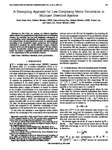
Figure 1. NAND circuit and its Graph equivalent.
The probability of the transistor to be turned OFF depends on the signal that reaches the transistor gate either directly from input or indirectly from previous transistor’s drain. In case of multi vectors at the transistor gate, An OR operation is performed to these vectors to generate the vector that represents the OFF state. The voltage difference between transistor drain and source equals VDD when the transistor source equals VDD and the drain voltage equals GND for PMOS transistor or vice versa for NMOS transistor.
The proposed algorithm, which is called Fast Input Vector Algorithm (FIVA), is an exact algorithm. It determines the input vector depends on the circuit structure. It generates a graph that represents the circuit, calculates the Sub-threshold leakage power for each node in the graph, and then uses Boolean logic and probability to find minimum Sub-threshold leakage vector. FIVA is considered optimal approach when it is compared with the ideal algorithm that performs a detailed simulation for all input vectors at the circuit level to find the vector that has the minimum leakage current. FIVA algorithm complexity is very small compared to other algorithms. When FIVA starts, it transfers the CMOS circuit into graph by representing transistors as vertices and the connections as edges, as shown at fig. 1.
The probability of transistor upper terminal to be VDD in case of PMOS transistor - depends on the signal that reaches the transistor source either directly from VDD or indirectly from previous transistor drain. In case of direct connection, the value of this vector (UpVector) is 1. In case of indirect connection, the UpVector is calculated by performing OR operation for all vectors, which results from making AND operation between the inverse of OFF state vector with the UpVector for each previous transistor that has connection to that transistor. The down terminal vector (DownVector) is calculated by the same way as the UpVector except that the direct connection is started from GND instead of VDD.
Fig. 1 shows the Graph representation for NAND gate. At the left of the graph, there are the input vertices, then transistors vertices, and finally output vertex at the right. Also, the figure shows the VDD and GND vertices which supply the transistors vertices in the NAND gate. One of the most important types of leakage current is Sub-threshold leakage, which occurs when the difference of voltage between transistor source and drain is VDD, and the transistor is turned OFF. About 85% of circuit Subthreshold leakage current occurs when the voltage difference of CMOS transistor drain and source is VDD [3]. FIVA finds the input vector which has the minimum number of transistors that satisfy this condition.
Table I shows the probabilities of NAND gate transistors for all combinations of inputs. The last column (P (Leakage)) represents the final result, which is the probability of producing leakage current for all combinations of input vectors. TABLE I.
The proposed algorithm depends on calculating the transistor probability of being OFF and the probability of voltage difference between drain and source to be VDD, as shown at equation 1. Leakage P (M) = P (MOFF) * P (Vds = VDD)
P( MOFF) A 0.5 B 0.5 P( MOFF)
P (Vs = VDD) 1 1 1 1 P (Vs = GND)
M3
A'
0.5
B
0.5
A+B
0.75
M4
B'
0.5
1
1
(A+B) .A
0.5
P M1 M2
(1)
N
The idea of the FIVA algorithm is based on that each transistor in the circuit has three victors; the first vector represents the transistor probability to be OFF. The second vector represents probability of the transistor upper terminal
85
NAND TRANSISTORS PROBABILITY
P (Vd = GND) AB AB
0.25 0.25
P (Vd = VDD)
P(Leakage) A.(AB)=AB B.(AB)=AB Leakage A'.B.(A+B) = A'.B A.B'.(A+B) = A.B'
ANDing operation between GateVector and DownVector for the transistor.
Table II shows the stages of applying FIVA algorithm on the NAND circuit. Each Column in the table represents the all possible values for the vector.
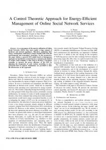
The final phase is shown from L14 to L18. It takes each transistor connected directly to the Output nodes. If the selected transistor has Input at its upper terminal, then its GateVector is the Input Vector. If the transistor is connected to another transistor, then recursion function, at L42-L52, is performed till it reaches the Input nodes. The return of the recursion function is the vector which produced from the ANDing operation between GateVector and UppVector for the transistor.
The UpVector column shows the probability for the transistor upper terminal to be VDD. Because M1 and M2 transistors are directly connected to VDD node, its UpVector is 1s. Transistor M3 depends on the state of the previous transistor because it is connected to M1 and M2. So, the probability of the upper terminal of M3 to be VDD is the result of the ORing operation between the down terminal of M1 and M2. The down terminal of M1 and M2 result from the ANDing operation between its GateVector (P (OFF)) and UpVector. The DownVector column shows the probability for the transistor down terminal to be GND. The GateVector (P (OFF)) vector shows the probability of the transistors to be turned OFF according to the circuit input vectors. Thus, M1 is turned OFF when the vector at its gate (GateVector) is [0011]. The last column (Leakage) is produced from making ANDing operation between the previous three columns. From table II, the last row shows the number of transistors that generates the Sub-threshold leakage current at every input. Hence, the minimum leakage vector for NAND gate is [00] input vector. The proposed algorithm is optimal because it finds the minimum leakage vector among all possible vectors, as shown in the simulation results. TABLE II.
M1 M2 M3 M4
L1: Start L2: Read Netlist file L3: Transform the circuit into Graph L4: For All (CMOS => GND ) L5 :{ L6 : Temp= get (CMOS => Source) L7 : TempUpVector = findUpp (Temp) L8 :} L9 : For All (CMOS => VDD ) L10 :{ L11 : Temp= get (CMOS => Drain) L12 : TempDownVector = findDown (Temp) L13 :} L14: For All (CMOS => Output ) L15:{ L16: Temp= get (CMOS => Source) L17: TempOutVector = findOFF (Temp) L18:} L19:End L20: FindUp (temp) L21:{ L22: If (temp == GND) L23: Return [1111] L24: Else L25: { L26: For All CMOS connected to upper terminal of temp L27: TempUpVector = ORi (findUp( temp => upper[i])) L28: Return TempUpVector AND INV( tempGateVector) L29: } L30:} L31:FindDown (temp) L32:{ L33: If (temp == VDD) L34: Return [1111] L35: Else L36: { L37: For all CMOS connected to lower terminal of temp L38: TempDownVector = ORi(findDown( temp => lower[i])) L39: Return TempDownVector AND INV( tempGateVector) L40: } L41:} L42:FindOFF (temp) L43:{ L44: If (temp == INPUT ) L45: Return INPUT_VECTOR L46: Else L47: { L48: For all CMOS connected to gate terminal of temp L49: TempOutVector = ORi(findOFF( temp => gate[i])) L50: Return TempOutVector L51: } L52:}
ALGORITHM OUTPUT AND ANALYSIS FOR NAND CIRCUIT.
A B UpVector DownVector P(OFF) A.B[0001] A[0011] VDD[1111] VDD[1111] A.B[0001] B[0101] A'+B'[1110] B[0101] A’[1100] (A'+B')A[0010] GND[1111] B’[1010] No. of transistors that have leakage
0 0 0 0 0 0 0
0 1 1 0 Leakage 0 0 0 0 1 0 0 1 1 1
1 1 1 1 0 0 2
Fig. 2 shows FIVA algorithm, it starts by reading the Netlist file of the circuit at transistor level. Then, it performs a transformation method to represent the circuit as a graph. This Graph is composed of CMOS, VDD, GND, Input, and Output nodes. The proposed Input Vector algorithm consists of three phases. All of these phases are recursion to save time and resources. The first and second phases are performed starting from VDD and GND nodes, consecutively. The third phase is performed starting by the output nodes. In fig. 2, the first phase is shown from L4 to L8. It starts by taking each transistor connected directly to the GND node. If the selected transistor has VDD at its upper terminal, then its UppVector is [1111]. If the transistor is connected to another transistor, then the recursion function, at L20-L30, should be performed till it reaches the VDD node. The return of the recursion function is the vector, which produced from the ANDing operation between GateVector and UppVector for the transistor.
Figure 2. FIVA Algorithm pseudo code.
IV.
SIMULASTION RESULTS
In order to prove that the proposed algorithm achieves the optimal results, we compared it with optimal method that has very high computation time and resources. This method is achieved by performing a detailed simulation for all input vectors at the circuit level to find the vector that has the minimum leakage current. The main idea of this method is to measure the circuit Sub-threshold leakage power for every single vector. Table III shows the comparison of runtime between the FIVA algorithm and the circuit level simulation method. The simulation is performed for C17
The second phase starts at L9 to L13. It takes each transistor connected directly to the VDD node. If the selected transistor has GND at its down terminal, then its DownVector is [1111]. If the transistor is connected to another transistor, then recursion function, at L31-L41, is performed till it reaches the GND node. The return of the recursion function is the vector which produced from the
86
benchmark and full adder circuits. At least, the proposed algorithm has a speed more than three times of the ideal algorithm.
100000 10000 1000
RUNTIME COMPARISON BETWEEN ALGORITHMS.
100 Time (s)
TABLE III.
10
FIVA Algorithm (sec)
Trying All Vectors (sec)
0.00083
0.0023
0.002706
0.00996
0.01
0.00785
0.09626
0.001
0.0483
0.761
0.2291
5.22
1.028
33.11
5.7
197.3
25.64
1120.64
225
11324
C17
1 0.1
2 bits Adder 3 bits Adder
5
4 bits Adder 5 bits Adder
7 bits Adder 8 bits Adder 9 bits Adder
4000 2000 0 7-bit
8-bit
9-bit
FullAdder Circuit FIVA
Time (S)
19
CONCLUSION
REFERENCES
6000
6-bit
17
[1] Johnson, M., Somasekhar, D. and Roy, K., “Models and Algorithms for Bounds in CMOS Circuits,” IEEE Trans. On CAD of Integrated Circuits and Systems, Vol. 18, No. 6, June 1999, pp. 714-725. [2] Ye, Y., Borkar, S., and De, V., “A New Technique for Standby Leakage Reduction in High-Performance Circuits,”Proc. of Symposium on VLSI Circuits, 1998, pp. 40-41. 22 [3] Lin Yuan and Gang Qu. A combined gate replacement and input vector control approach for leakage current reduction. IEEE Trans. Very Large Scale Integr. Syst., 14(2):173–182, 2006. [4] D. Duarte, Y. Tsai, N. Vijaykrishnan, and M. Irwin, “Evaluating RunTime Techniques for Leakage Power Reduction”, IEEE International Conference on VLSI Design, pp. 31-38, 2002. [5] D. Lee,W. Kwong, D. Blaauw, and D. Sylvester, “Analysis and Minimization Techniques for Total Leakage Considering Gate Oxide Leakage”, ACM/IEEE Design Automation Conference, pp. 175-180, June 2003. [6] J. Halter, and F. Najm, “A Gate-Level Leakage Power Reduction Method for Ultra Low Power CMOS Circuits”, IEEE Custom Integrated Circuits Conference, pp 475-478, 1997. [7] R.M. Rao, F. Liu, J.L. Burns, and R.B. Brown, “A Heuristic to Determine Low Leakage Sleep State Vectors for CMOS Combinational Circuits”, IEEE International Conference on Computer-Aided Design, November 2003. [8] K. Chopra and S.B.K. Vrudhula, “Implicit Pseudo Boolean Enumeration Algorithms for Input Vector Control”, ACM/IEEE Design Automation Conference, pp. 767-772, 2004. [9] S. Naidu & E. Jacobs, “Minimizing stand-by leakage power in static CMOS circuits”, Proc. DATE, 2001, pp.370-376. [10] Z. Chen, M. Johnson, L. Wei, and K. Roy, “Estimation of Standby Leakage Power in CMOS Circuits Considering Accurate Modeling of Transistor Stacks”, International Symposium on Low Power Electronics and Design, pp. 239-244, 1998. [12] Bobba, S. and Hajj, I., “Maximum Leakage Power Estimation for CMOS Circuits,” Proc. of the IEEE Alessandro Volta Memorial Workshop on Low-Power Design, 1999, pp. 116 –124. [13] A. Abdollahi, F. Fallah, and M. Pedram, “Leakage Current Reduction in CMOS VLSI Circuits by Input Vector Control”, IEEE Trans. on VLSI, Vol. 12, pp. 140-154, Feb. 2004. [14] F. Aloul, S. Hassoun, K. Sakallah, D. Blaauw, “Robust SAT-Based Search Algorithm for Leakage Power Reduction”, International Workshop on Integrated Circuit Design, pp. 167-177, 2002. [15] F. Gao and J.P. Hayes, “Exact and Heuristic Approaches to Input Vector Control for Leakage Power Reduction”, Proceedings of ICCAD pp. 527-532,2004.
8000
5-bit
15
Input Vector Control is very efficient approach to reduce leakage power. The Sub-threshold leakage depends mainly on the input vector of the circuit. FIVA algorithm finds the best input vector, which has the least Sub-threshold leakage power. It has a linear relation with the number of inputs which is considered small when compared with exponential relation.
10000
4-bit
13
Ideal
V.
12000
3-bit
11
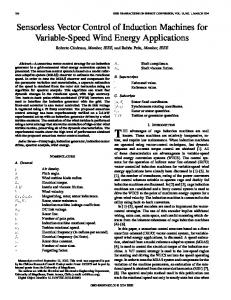
Figure 4. The required time via number of input in log scale
Fig. 3 and fig. 4 show the behavior of the proposed algorithm, which is almost linear when compared to the ideal algorithm, which is exponential. When the proposed algorithm is compared with other algorithms like [6, 7, 9, 10], It is clear that these algorithms are not complete or optimal. Actually, these algorithms reach a good state but it is not the optimal.
2-bit
9
Number of Input FIVA
6 bits Adder
7
Ideal
Figure 3. The relation between number of inputs and runtime for FIVA and the ideal algorithms.
87