The detection of line segments is a problem present in a number of image analysis applications. Traditional image analysis operators usually function at the ...
A Fast Method for Detecting and Matching Linear Features in Images Thomas Lee and Hugues Talbot CSIRO Division of Mathematics and Statistics Locked Bag 17, North Ryde, NSW 2113
Introduction The detection of line segments is a problem present in a number of image analysis applications. Traditional image analysis operators usually function at the local level, whereas line recognition is known to be a non-local process. Indeed, the human vision system is very good at detecting and extrapolating linear features which are not obvious at the pixel level. In this abstract, we outline a fast method that uses both local and non-local information to detect linear features in images.
1
Linear segment detection
The method we propose first relies on local information to find markers where linear features might be found. This detection can occur in a number of different ways, depending on the content of the image. We propose a number of methods based on mathematical morphology techniques (MM) [6]. For example in the case of faint bright lines on a noisy background, we propose extracting extended regional maxima [8] from an image filtered by a connected operator such as an area opening [7]. This will extract small bright areas from the image. These maxima are filtered by a thinning by attributes [1], which retain only those bright areas that have a high length to width ratio. As a rule, such marker extraction techniques are reputed not to be robust. To improve the robustness of this technique, two different sets of markers are extracted, using different parameter values. A first, stringent set of parameters is determined that ensures that the 1
markers found using those parameters indeed belong to linear features. We call these markers the minimal markers. A second set of parameters allows more markers to be found, together with a reasonable amount of unwanted noise. We call these markers the maximal markers. This double set of markers is then processed with the following proposed line segment reconnection algorithm.
2
Line segment reconnection
We propose to replace each marker in the image by its best-fitting ellipse [5, 237-234]. This allows considerable simplification of the semantic content of the image. Each marker is reduced to a set with position, orientation, length and width information. This allows the use of nonlocal criteria to match the detected markers.
2.1
General line reconnection procedure
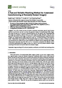
The first step is to try and match each major axis extremity of those ellipses with all the other available extremities (see Fig. 1). The score function associated with each possible reconnection is: Score = λ
s
2π − α − β d + (1 − λ) , 2π diag
(1)
where α and β are the angles between the line constituting the possible reconstruction and the main axis of each of the ellipses. The parameter d is the Euclidean distance between the 2 extremities. The diag parameter is the length of the diagonal of the image and λ is an adjustable parameter. This function shows that a reconnection will be more probable when the distance between the two extremities decreases, and the angle between the reconnection line and the main axis of both ellipses tends to π, i.e., when the ellipses are well aligned. The reconnection which has the best score is performed. When no possible reconnection reaches a sufficient score, no reconnection is performed. Also, when two extremities are very close to each other, the reconnection is performed regardless of the angle. The result of this processing is shown in Fig. 1d.
2.2
Reconnection of a double set of markers
This procedure is further improved when using two sets of markers instead of one: 2
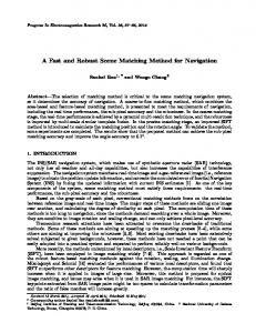
Let the minimal markers and the maximal markers be those defined in section 1. The procedure is to try and connect together the minmal markers, but if some maximal markers have the right alignment and the right orientation with respect to at least one minimal marker, these maximal markers can become minimal markers and be used in the general reconnection procedure. We show that the reliability and the robustness of the reconnection is increased this way. Fig. 2 illustrates this point: in this scanning electron microscope image of man-made vitreous fibres, we want to segment the small fibres in order to be able to measure their length for quality control purposes. The double marker approach allows the retrieval of the full length of both fibres, whereas using the minimal marker alone would result in an incorrect length measurement, and using the maximal markers alone would result in an oversegmentation of the image leading to incorrect results.
3
Extension and performance
In the paper, we show that we can apply the general line reconnection method to a number of related line detection and matching problems, such as the management of overlapping objects. We also show that this method is very fast, even if there are several hundreds of markers. It usually takes only a few seconds to perform marker detection and matching from start to finish, on 512 × 512 images, on a standard Sun Sparc 10 workstation. We compare the proposed method with a number of other published methods giving similar results, such as for example least-square fitting [2], Hough-transform based methods [3] or marker propagation [4]. We show that the proposed method gives comparable results to those methods but is faster.
References [1] E.J. Breen and R. Jones. Parameter based openings, thinnings and granulometries. Submitted for publication, 1995. [2] S. A Dunani and A. L. Luk. Locating straight-line edge segments on outdoor scenes. Pattern Recognition, 10:145–157, 1978. [3] R.C. Gonzales and P. Wintz. Digital Image Processing. Addison-Wesley, 2nd edition, 1987.
3
[4] M.B. Kurdy and D. Jeulin. Directional mathematical morphology operations. In Proceedings of the 5th European Congress for Stereology, volume 8/2, pages 473–480, Freiburg im Breisgau, Germany., 1989. Acta Stereologica. [5] A. Rosenfeld and A. Kak. Digital Picture Processing, volume 2. Academic Press, London, 2nd edition, 1982. [6] J. Serra. Image Analysis and Mathematical Morphology. Academic Press, 1982. [7] L. Vincent. Grayscale area openings and closings, their efficient implementation and applications. In Proceedings of the conference on mathematical morphology and its applications to signal processing, pages 22–27, Barcelona, Spain, May 1993. [8] L. Vincent. Morphological grayscale reconstruction in image analysis: Applications and efficient algorithms. IEEE Transactions on Image Processing, 22(2):176–201, 1993.
4
(a) Markers
(b) Best-fitting ellipses
α A B β
(c) Reconnection on point A
(d) Final reconnection
Figure 1: General reconnection procedure.
5
(a) Original image
(b) minimal markers
(c) maximal markers
(d) Final reconnection
Figure 2: Reconnection using a double set of markers.
6