A new fast matching method for adaptive compression of stereoscopic images a
A. Ortis*a, S. Battiato**a Università degli Studi di Catania – Dipartimento di Matematica e Informatica Image Processing Lab - iplab.dmi.unict.it Viale A. Doria 6, 95125 – Catania – Italy ABSTRACT
In the last few years, due to the growing use of stereoscopic images, much effort has been spent by the scientific community to develop algorithms for stereoscopic image compression. Stereo images represent the same scene from two different views, and therefore they typically contain a high degree of redundancy. It is then possible to implement some compression strategies devoted to exploit the intrinsic characteristics of the two involved images that are typically embedded in a MPO (Multi Picture Object) data format. MPO files represents a stereoscopic image by building a list of JPEG images. Our previous work introduced a simple block-matching approach to compute local residual useful to reconstruct during the decoding phase, stereoscopic images that maintain high perceptual quality; this allows to the encoder to force high level of compression at least for one of the two involved images. On the other hand the matching approach, based only on the similarity of the blocks, results rather inefficient. Starting from this point, the main contribution of this paper focuses on the improvement of both matching step effectiveness and its computational cost. Such alternative approach aims to greatly enhance matching step by exploiting the geometric properties of a pair of stereoscopic images. In this way we significantly reduce the complexity of the method without affecting results in terms of quality. Keywords: Stereoscopic Images, Image Compression, Multi Picture Object, Epipolar Geometry.
1. INTRODUCTION Stereoscopy is a technique to create the illusion of depth. MPO (Multi Picture Object) is a file format used to store multipicture images2, that represents a stereoscopic image by a chain of still JPEGs embedded in a single file with specific tags. A stereoscopic image is composed by two images of the same scene taken from two different points where the reciprocal distance between corresponds to the interocular distance in the human visual system. A MPO file needs roughly the same storage space of two JPEGs; since the involved scene is the same for both images, there is a lot of redundant information. Some approaches for stereoscopic images compression have been recently proposed123. In our previous approach1 is described a encoder/decoder engine which uses the redundant information between stereoscopic views in order to reduce the bitrate of a stereoscopic pair applied on MPO files. Results reported a sensible reduction of the overall size of MPO files with a very low visual degradation. Although this algorithm provides effective results, the matching step involves very high computational costs because of the NCC (Normalized Cross Correlation) based matching 11. Perkins’s approach2 requires a transmission format which could not replace established image formats. Schenkel et al.3 proposed a joint decoding approach which enhances the quality of the image pairs independently compressed with JPEG, but some regions of the processed image cannot possibly be reconstructed and, with a middle quality of JPEG compression, there are PSNR decrease and some ghosting artifacts appear seldom3. Our previous work1 implements an asymmetric block-based coding scheme where the two images of a stereopair are encoded using different JPEG quality factors; this let to reduce the size of MPOs. Then, during the decoding process, the *
[email protected];**
[email protected];
low quality image is enhanced using the redundant information of the high quality one. The decoding process consists in a block based algorithm which subdivides both images in not overlapping blocks of equal dimensions and works block by block on each channel plane. The first step consists in finding the block of the high quality image which better approximates the considered block of the low quality image; the adopted strategy exploits a template matching method based on the normalized cross correlation5 (NCC). Evaluating the NCC value for each position of a given template in the reference image (the image where the template is searched) it points out the best position in terms of correlation coefficient. The second step consists of enhancing the processed block using the information of the block achieved by means the matching method. The function used for this step is based on a simplified version of Kohonen reconstruction 6 and works sample by sample. Although this algorithm provides effective results, the matching step involves very high computational costs because of the NCC (Normalized Cross Correlation) based matching; moreover, the information obtained by matching is not always useful. In fact, it is used only if it is similar to the processed block. Computational issues are also due the usage of very large blocks. Therefore this matching approach, based only by the similarity of the blocks, results rather inefficient. Ultimately, we highlight that the entire process is applied for each channel, thus each block is processed three times. The main contribution of this paper focuses on the improvement of the matching step efficiency and its computational cost. This alternative approach aims to improve the overall approach by exploiting the geometric properties of a pair of stereoscopic images, reducing the complexity of the method. The employed technique uses a fixed size for the blocks, and it makes the matching for each channel at the same time. The algorithm has been applied to the same dataset of the previous work1 using the same enhancing method. Experiments confirm the effectiveness of the proposed approach, which drastically reduces the computational costs without pay anything both in terms of bitrate saving and quality of the reconstructed images. The paper is organized as follows: Section 2 after a brief introduction of the epipolar geometry describing the fundamental matrix and its properties, describes the proposed algorithm; in Section 3 test and result are discussed. Finally, Section 4 closes the paper giving some ideas for future works.
2. PROPOSED METHOD 2.1 Epipolar geometry Epipolar geometry is the set of rules which describe the relationships and the geometrical constraints between two 2D images of the same 3D scene taken from different views. It is independent of scene structure, but only on the cameras’ internal parameters and the relative pose7. The fundamental matrix F is a 3-by-3 matrix of rank 2 which encapsulates this intrinsic geometry, and can be defined as 𝑥′1 𝐹𝑥2 = 0
(1)
where 𝑥1 and 𝑥2 are two corresponding image points between the two images. These points are obtained by imaging the same 3D point in the first and in the second image respectively. Thus, if two points taken from two images of a stereopair represent the same real world point, the equation (1) must be satisfied. In the proposed method, the fundamental matrix is used to drastically reduce the search range of correspondences between the two images. In fact, due to the point-line dualism theorem of the epipolar geometry, given a specific point 𝑥1 of the first image we can obtain the locus of points in the second image where the corresponding point of 𝑥1 lies. It is possible to obtain the implicit parameters of the epipolar line 𝑙2 in the second image corresponding to 𝑥1 with the following equation: 𝑙2 = 𝐹𝑥1
(2)
2.2 Image blocking method In the previous work1, images are subdivided in big blocks, then each block (for each channel of the YCbCr space) is compared with the corresponding high quality image using an NCC based template matching strategy. Block size is chosen adaptively for each image in order to cover all the image without blocks overlap just managing a few number of blocks.
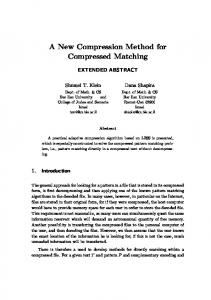
Figure 1. Example of blocking substitution using r=20 in the image “Flowers1” of the dataset used in [1]. In this example we obtain 972 blocks.
The limit of this approach is that such big blocks contains several information about the different objects and structures of the involved scene, and each object maybe appear slightly different in the two images due to the view change. Thus, the matching of the most similar block results coarse and computationally heavy. In the proposed method the images are subdivided in very little blocks (the radius is typically less than 25 pixel as detailed below). All blocks share the same dimensions and the matching method is performed at the same time for each block (for all channels). Given a radius r (in our experiments r=20) the algorithm subdivides the low quality image using (r+1)× (r+1) blocks. If necessary, the blocks of the last column and those ones of the last row may overlap the blocks of penultimate column and penultimate row respectively. Figure 1 shows the blocking method applied on the image “Flowers1” of the dataset1, the overlapping blocks in the last column and in the last row are drawn in blue, the other blocks are drawn in red. In this way we employ a fine-grained search of the processed data avoiding to work with big matrices. Just considering the same image, method used by Ortis et al. 1 makes use of just 12 blocks with size 360×360, whereas the proposed method defines 972 blocks. 2.3 Matching method The main improvement of the algorithm is provided by the matching method. We conventionally use the left as the high quality image and the right one as the low quality image. For each processed block bi of the right image, our method estimates the epipolar line li of its center ci which lies on the left image. The corresponding point of ci in the right image lies on this line, so we can search the best matching block of bi shifting its center along li. So that, the main benefit is that the search to the point corresponding to ci can be restricted to the epipolar line. The search range is limited by the width of the image, but, as discussed in Section 2.4, the proposed method further reduce it. The matching method is not based only by the similarity, it uses a similarity based approach driven by strong geometric constraints; this aspect permits us finding the best matching block considering all the channels at the same time. In order to estimate the epipolar lines we used the equation (2), so that we needed to estimate the fundamental matrix. This can be done using some initial points correspondences between images. Equation (1) shows that each matching pair of points between the two images provides a single linear constraint on F. This allows F to be estimated linearly from at
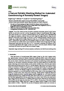
Figure 2. Nine points taken from the right image and corresponding epipolar lines in the left image.
Figure 3. Detail of the previous figure showing the point number eight and its epipolar line.
least 8 independent correspondences using the so called 8-point algorithm8, the main advantage of this algorithm is its simplicity of implementation, but it is rather susceptible to wrong correspondences. In our experiment we estimated F using two methods: 1) The 8-points algorithm: this method is very effective but to produce reliable results the input points must match precisely. 2) Least Meadian of Squares: is a robust estimation method resistant to outliers. It requires that at least 50% of the correspondences are inliers. In order to find the corresponding points in a stereo pair we used two kind of features: SIFT and Harris keypoints 9. Figure 2 shows nine points in the right image and correspondent epipolar lines in the left image computed as above. The points drawn on the left image are not the correspondents to the ones on the right image, but just the points in the epipolar line which has the same x coordinate as the points in the right image. Figure 3 shows the detail of the point number eight: this point is placed on the center of the flower’s pistil in the right image, its epipolar line passes correctly by the corresponding point in the left image and the point with the same x coordinate which lies on this line appears shifted with respect to the corresponding one. So that, given a point in the right image, the correspondent point we are looking for lies on the epipolar line and it is not too far from the point with the same x as the right one.
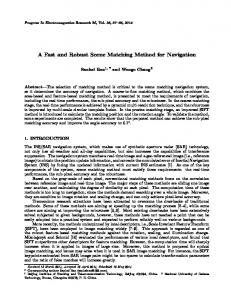
Figure 4. An example of 𝛷 (on the left) and the detail around the vertex of 𝛷 (on the right). The red circle is the point on 𝛷 with the same x as the point on the right image.
2.4 Range reduction Given a block bi of the right image, we can estimate the epipolar line of its center ci and just search the best matching block of bi considering all possible blocks taken by shifting bi along li. However the number of these blocks can be reduced by observing that: a)
The y coordinate of the center of the block we are looking for is given by the epipolar line values, whereas the x coordinate is not too different by the x of the point in the right image, i.e. the x coordinate of the center of the processed block.
b) If 𝑥1 and 𝑥2 are two corresponding points, they are related by the equation (1). In order to reduce the searching range, we proceed as follows. Given a point 𝑥1 on the right image (the center of the processed block) and its epipolar line l1, for each point 𝑥2 in l1 in we compute the value of 𝑥′1 𝐹𝑥2 . The result is a zero crossing line and, according to (b), the corresponding point lies around the point where the line passes from zero. In order to highlight this region, we then compute the following equation 𝛷 = (𝑥′1 𝐹𝑥2 )2
(3)
the curve 𝛷 is a parabola whose vertex is close to zero. Figure 4 shows an example of 𝛷 and the detail around its vertex. The value of 𝛷 grows rapidly with the distance from the vertex and, as observed before, the point with the same x coordinate as ci is nearby the vertex. The searching range reduction is obtained by applying a threshold to 𝛷 in order to consider just few points around its vertex. In our experiment we first used the value 2,3 and this heuristic permitted to exclude a significant number of candidate blocks (this is easy to notice by observing Figure 4). Nevertheless in some cases a fixed threshold resulted rather restrictive, so that we applied two adaptative rules: 1) If the range obtained by thresholding does not include the point with the same x as ci, according to (a), the threshold is augmented until the range includes also this point. 2) If the range obtained by thresholding does not include any point, the threshold is augmented iteratively of 0,5 until the range is not empty. These rules permitted us to implement an effective adaptive thresholding approach.
Figure 5. The block number 111 (figure a), the partial matching block (figure b) and the composed block (figure c).
2.5 Block matching Once we have reduced the searching range, given a block bi of the right image our approach searches the best matching block of bi considering the candidate blocks whose center lies in li and has a value of x in the relative range. The difference between bi and the candidate blocks is computed using the well known SSD (Sum of Squared Differences); the best matching block is then used in the enhancing step with the same approach used in [1]. The enhancing step uses the following equation:
biR u, v biR u, v biL u, v if biR u, v biL u, v limit bi u, v biR u, v otherwise R
where bi
R
u, v
(4)
is the enhanced pixel, bi u , v is the pixel of the block chosen by the matching approach and L
biR u , v is the pixel which has to be enhanced. The constants α and limit (in our cases α = 0,25 and limit = 0,043) are
two coefficients used to manage the amount of correction of the Kohonen reconstruction. This function works sample by sample and returns the enhanced block. Tests have shown that such a matching method could fail with uniform blocks, expecially if the employed threshold is not low enough to exclude false positive blocks. This happens because when the right and the left image are different in luminance, correspondent uniform areas appear rather different and the matching method could take a different block (belonging to another uniform area). Thus, in these cases, even if we found the correct block from the geometrical point of view, the difference between pixel values makes these blocks not useful for the next phase of enhancement. Using a low threshold we avoid to consider blocks that are too far from the best matching block. Moreover, considering that JPEG encoding preserves low frequency information, the pixel affected by JPEG in these blocks would be so few that a plausible option would be to not process them. Discard blocks with low variance allowed us to decrease the number of candidate blocks and avoid matching errors caused by uniform blocks. Test has shown that this approach doesn’t affect the results in terms of quality. So that, this permitted us to speed up the matching process maintaining the same performance in terms of quality. 2.6 Partial matching When the processed block is located nearby the border of the image, the corresponding block could be not found or just partially matched in the other image. In order to consider also partial matching, the proposed approach accepts candidate blocks whose dimensions are at least the 60% of the dimensions of the processed block. When such partial block is considered as a candidate for matching, the missing information are filled using the pixel of the processed block and then the SSD is computed using this composed block. For instance, Figure 2 shows that in the right image is visible a chandelier that is just partially shown in the left image. When the algorithm processes the block b111 which represents the part of the chandelier shown by both images (Figure 5a), it considers also a partial matching with a 41x25 block placed on the left side of the reference image (Figure 5b). The blue pixels represents the missing part which are filled with the information of b111 obtaining the composed block (Figure 5c).
3. TEST AND RESULTS We evaluated the proposed approach changing both the correspondence detection (using SIFT or Harrys keypoints detection) and the fundamental matrix estimation methods (using the 8-points algorithm or the Least Meadian of Squares optimization). In general, the SIFT detection and matching yields a great number of correspondences with some outliers, whereas Harrys keypoints technique yields a fewer number of correspondences but with less outliers. The best method for estimating the fundamental matrix depends on the number and the quality of the correspondences. All experiments confirmed that the proposed approach drastically reduces the computational costs and allows to obtain the same performance in terms of image quality. To evaluate the performances of the proposed method we have used the same dataset10 used in the paper by Ortis et al.1. This is composed of 23 stereo MPO images conform with the CIPA standard4 at various resolution sizes (1440x1080, 1444x1080, 1620x1080, 1920x1080 or 1924x1080). In our settings JPEG quality factor has been set to 85 for the high quality image and 70 for the low quality image. As resulted in the previous work, using this settings the bitrate saving is between 30% and 42% and the lossy is between 1,32 dB and 2,76 dB (using PSNR as quality metric). 3.1 Computational improvement The computational complexity of normalized cross correlation used for finding matches of a reference template of size mxn in a scene image of size MxN is 𝑂(𝑚𝑛𝑀𝑁), thus the cost of NCC based matching, for each mxn block, is 𝑇𝑁𝐶𝐶 = 𝑂(𝑚𝑛𝑀𝑁)
(5)
𝐵 = 𝑀𝑁⁄𝑚𝑛
(6)
Let B the number of blocks
the total cost due to the matching method used in [1] is 𝑇 = 𝐵 ∙ 𝑂(𝑚𝑛𝑀𝑁) = 𝑂(𝑀2 𝑁 2 )
(7)
The cost of SSD between two mxn blocks is 𝑂(𝑚𝑛), thus the cost due to the matching method used in our approach is 𝑇𝑚𝑎𝑡𝑐ℎ𝑖𝑛𝑔 = 𝑘 ∙ 𝑂(𝑚𝑛)
(8)
where k is the number of compared blocks, this number is very low because our range reduction strategy and it is negligible with respect to the term 𝑂(𝑚𝑛). Thus, if B is the total number of mxn blocks, the total cost due to the matching step is 𝑇 = 𝐵 ∙ 𝑂(𝑚𝑛) = 𝑂(𝑀𝑁)
(9)
In the above computational analysis the cost of the enhancing step is not considered because is the same for both approaches and is lower than the matching one. The enhancing step is applied one time for each pixel, thus its overall cost is linear, and can be simply added to the total cost of the matching step that is higher. So that, we can consider just the total cost of the matching step for the computational cost analysis.
4. CONCLUSION We have presented a stereoscopic image compression approach which outperforms our previous work 1. The results of comparative tests with the work by Ortis et al.1 have shown that the proposed technique provides the same effective results both in terms of perceptual quality and PSNR values as in the previous work1, but it drastically improves the computational costs reducing the runtime of the reconstruction algorithm. The proposed approach exploits the redundant information between stereo pairs reducing the size of MPOs. Tests have shown that by imposing some constraints given by the epipolar geometry, the proposed method allows obtaining an efficient and fine-grained matching step that cuts down the computational costs, but maintaining the same performance in terms of quality of result. The computational analysis shows that this method improves the efficiency of our previous work 1 by reducing its order of growth from quadratic to linear with respect to the number of the pixels in the image.
REFERENCES [1] Ortis, A., Rundo, F., Di Giore, G. & Battiato, S. (2013). Adaptive Compression of Stereoscopic Images. In Image Analysis and Processing–ICIAP 2013. Volume 8156, (pp. 391-399). Springer Berlin Heidelberg. [2] Perkins, M.G., Data compression of stereopairs, Communications, IEEE Transactions on , vol.40, no.4, pp.684696 (Apr 1992). [3] Schenkel, M. B., Luo, C., Frossard, P., & Wu, F. (2010, September). Joint decoding of stereo JPEG image Pairs. In Image Processing (ICIP), 2010 17th IEEE International Conference on (pp. 2633-2636). IEEE. [4] Multi-Picture format, Camera & Imaging Products Association Standardization Committee (CIPA) (2009). [5] Briechle, Kai, and Uwe D. Hanebeck. Template matching using fast normalized cross cor-relation. In Aerospace/Defense Sensing, Simulation, and Controls, pp. 95-102. International Society for Optics and Photonics, (2001). [6] Kohonen, Teuvo. "The self-organizing map." Proceedings of the IEEE 78.9 (1990): 1464-1480. [7] Hartley, R. I., and Zisserman, A., [Multiple View Geometry in Computer Vision], Cambridge University Press, Cambridge, Chapter 9 (2004). [8] H. C. Longuet-Higgins. A computer algorithm for reconstructing a scene from two projections. Nature, 293:133-135, Sept 1981. [9] Harris, C., and M. Stephens, "A Combined Corner and Edge Detector," Proceedings of the 4th Alvey Vision Conference, August 1988, pp. 147-151. [10] 3DMedia – 3D Technology and Software, www.3dmedia.com/gallery (accessed November 2014). [11] Briechle, Kai, and Uwe D. Hanebeck. Template matching using fast normalized cross correlation. In Aerospace/Defense Sensing, Simulation, and Controls, pp. 95-102. International Society for Optics and Photonics, (2001).