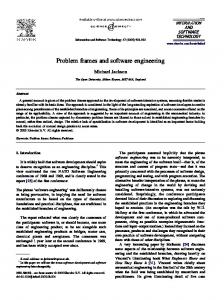
quality requirements in software development is not yet as well mastered as the ..... MSC for the problem diagram related to the goal Meter Reading for billing.
A Framework for Combining Problem Frames and Goal Models to Support Context Analysis during Requirements Engineering Nazila Gol Mohammadi, Azadeh Alebrahim, Thorsten Weyer, Maritta Heisel, Klaus Pohl paluno - The Ruhr Institute for Software Technology, University of Duisburg-Essen, Germany {nazila.golmohammadi, azadeh.alebrahim, thorsten.weyer, maritta.heisel, klaus.pohl}@paluno.uni-due.de
Abstract. Quality requirements, like security requirements, are difficult to elicit, especially if they cross multiple domains. Understanding these domains is an important issue in the requirements engineering process for the corresponding systems. Well-known requirements engineering approaches, such as goal-oriented techniques provide a good starting point in capturing security requirements in the form of soft-goals in the early stage of the software engineering process. However, such approaches are not sufficient for context and problem analysis. On the other hand, the context and problem modeling approaches like e.g., problem frames, do not address the system goals. Integrating the relevant context knowledge into goal models is a promising approach to address the mutual limitations. In this paper, we propose a framework for combining goal models and problem frames. The framework makes it possible to document the goals of the system together with the corresponding knowledge of the system’s context. Furthermore, it supports the process of refining (soft-) goals right up to the elicitation of corresponding security requirements. To show the applicability of our approach, we illustrate its application on a real-life case study concerning Smart Grids. Keywords: Requirements engineering, security requirements, problem frames, goal modeling
1
Introduction
Requirements engineering (RE) is an engineering activity that ties up the development activities with the real-world problems. It performs a series of activities based on the recognition of a problem to be solved and leads to a detailed specification of that problem [1]. This specification includes the requirements of the system-to-be in a way that the system meets the expected quality concerns of the stakeholders as well as the functional ones. Although the treatment of quality requirements in software development is not yet as well mastered as the treatment of functional requirements [2], it has recently caught more attention. Quality requirements such as security requirements must be elicited, analyzed, and documented as thoroughly as functional ones. Understanding the context is an important issue in RE for eliciting and analyzing requirements. During context analysis, the analyst anticipates how the
system-to-be will be integrated in its real world context, once it is in operation. Due to the fact that the size and complexity of the environment (context) of typical software-intensive systems, e.g., as integrated in smart grid, grew very fast in the last decade, e.g., systems-of-systems, the context analysis activities during RE become more and more crucial. Context analysis techniques support the requirements engineer to specify the requirements of the system in a systematic way. Therefore, the first mandatory task in RE is to know and explore the context, which the system will interact with. Focusing on the system itself prior to modeling its context lacks considering domain knowledge in eliciting requirements. The elicited requirements might be built on incomplete or even wrong domain knowledge. This can lead to failure of the system due to incorrect or incomplete requirements. Considering security requirements, this might be even more costly and disastrous because of business critical data losses and violation of security rules or any unacceptable outcome. Goal modeling approaches support the elicitation of system purposes in the RE process, but they have shortcomings as well. First, they tend to be inadequate and imperfect in describing the problem context [3]. Second, the goal models grow quickly, posing a threat to manageability and traceability [4]. Third, goals are hierarchical, hence, it sometimes becomes difficult to determine where a goal is situated in the hierarchy and how it relates to the problem context. Moreover, for every goal, there is always a discoverable super-goal. Thus, goal modeling techniques need to be bounded by the problem domain [5]. Problem frames [6] are concerned with the context modeling and the understanding of the context in RE. They analyze the problem context as it is in the real world. However, they lack addressing the goals of the system under consideration. Therefore, problem frames have the potential to be combined with other RE techniques, such as goal-oriented approaches [7, 8]. Goal-oriented approaches investigate goals of the system, whereas in problem frames goals can be identified by investigating the context of the problem. The relationship and the gap we identified between problem frames and goal-oriented approaches suggest the combination of these techniques. In the problem frames approach, there is no way to connect the requirements to the goals or to identify new goals. The goals can be identified by determining why we want to find a solution for this problem. After finding the way to identifying the goal, which is relevant to analyze the specific problem, the goal could be connected to the requirements. On the other hand, both approaches are not able to show the dynamic behavior of the situation. They are not expressive in showing requirements behavior and the real world interactions. In this paper, we propose a framework based on problem frames and goal models with support of Message Sequence Charts (MSCs) [9] that provides support for the RE phase. The dynamic behavior of the problem context is modeled using MSCs. The gaps and drawbacks mentioned above are addressed using our framework. This combination can provide a good understanding and overview of the real world prior to structuring the system and map the problem to its solution. The remainder of this paper is organized as follows: In Section 2 we explain the fundamentals of our method. Section 3 presents our approach for combining problem frames and goal models to support context analysis during requirements engineering. To demonstrate the usefulness of the framework we demonstrate
its application on a case study taken from the smart grid domain in Section 4. Section 5 discusses related work. Finally, Section 6 gives a conclusion and sketches future work.
2
Fundamentals
In this section we briefly introduce the problem frames approach, goal modeling, and the use of MSCs in RE. These techniques are the fundamentals for the framework that is described in Section 3. 2.1
Problem Frames
Problem frames [6] are one of the RE approaches, located in the early life-cycle of software engineering. Problem frames capture information from the context of the system in a simple way. A problem frame consists of domains, interfaces between them, and a requirement. Domains describe entities in the real world that are distinguished in three different types: biddable domains that are usually people, causal domains that comply with some physical laws, and lexical domains that are data representations. Interfaces connect domains, and they contain shared phenomena. Shared phenomena may be events, operation calls or messages. They are observable by at least two domains, but controlled by only one domain, as indicated by the name of that domain and “!”. An example can be find in Section 4 (see Fig. 6). When we state a requirement, we want to change something in the world with the machine (e.g., software) to be developed. Therefore, each requirement constrains at least one domain. Such a constrained domain is the core of any problem description because it has to be controlled according to the requirements. Hence, a constrained domain triggers the need for developing a new software (the machine) that provides the desired control. A requirement may refer to several domains in the environment of the machine. The task is to construct a machine that improves the behavior of the real world (in which it is integrated) in accordance with the requirements. According to the problem frames approach, the problem is decomposed into subproblems, which are represented by problem diagrams. A problem diagram consists of a submachine, the relevant domains, the interfaces between these domains, and a requirement. In this paper we describe problem frames using UML4PF (UML profile for Problem Frames) [10, 11] that is based on UML class diagrams. In Section 4, we model the context of our application example using the UML notation for problem frames. 2.2
Goal Modeling
In the RE community, goal modeling approaches have gained considerable attention. These approaches aim at capturing the rationale for the software system development. Goal models are mostly represented in tree-like structures that define the intentions of different stakeholders at different levels of abstraction [12]. Goal modeling links the high-level goals to the low-level requirements [13]. Goal-oriented approaches, such as KAOS [13], i* [14] and goal graphs [12], seek
reasons or purposes to design the system (purpose of the system). These approaches use AND/OR connectors to represent the goal decomposition and to define the alternative solutions for fulfilling the super-goal. Goals can be classified into two different categories: hard-goals and soft-goals. Hard-goals may refer to the functional properties of the system behavior, whereas, soft-goals represent quality preferences of the stakeholders. Soft-goals can be achieved at different levels of satisfaction, which means that there is no clear-cut definition for their satisfaction. Examples can be find in Section 4 (see Fig. 5 and Fig. 8). In KAOS notation the goals are modeled as parallelograms and soft-goals in form of dashed parallelograms. Among different goals in the hierarchy of KAOS goal model, there are either AND-refinement or OR-refinement. A positive or negative influence on a soft-goal can be represented using +, ++ or -, - -. A contribution operator represents a positive (+, ++) or negative (-, - -) influence on soft-goals. It documents to which level of satisfaction a soft-goal is influenced either positively or negatively. 2.3
Message Sequence Charts
MSCs [9] have proven to be successful in system development, in particular for RE. They are widely used for the concrete description of not only the system behavior, but also the context. They are especially used to describe the context behavior by requirements engineers and later validate the requirements for an acceptance test. In addition, they provide a convenient notation to describe behavioral requirements in the form of interaction diagrams. MSC consists of a set of actors/entities of the system (boxes), life-lines (vertical dashed lines), messages between the actors (arrows), and states (ovals). Actors can send and receive messages ordered by their occurrence within their life-lines. The state of different actors may be changed upon to receiving a message. An example can be found in Section 4 (see Fig. 7). When using MSCs for modeling behavioral requirements the corresponding diagram specifies the flow of interactions between the system and its context that has to be performed to satisfy a specific purpose of the system.
3
Framework for Combining Problem Frames and Goal Models to Support Context Analysis
We show how the problem frames approach can be enhanced by linking goals to the problem diagrams satisfying that goal. The goal in the KAOS goal model (Goal X in Fig. 1) will be localized by setting up a problem diagram. By using the established problem diagram, domains that contribute to the satisfaction of Goal X will be identified. The Goal X in the KAOS model is modeled in the problem diagram, as well as using the stereotype �goal�. The Requirement(s) in the problem diagram (Fig. 1) is a placeholder for requirements, which will be elicited when using our method. Requirement(s) for satisfying the goal under consideration (e.g., Goal X) will be elicited with the knowledge gained from domain analysis based on domains and phenomena between them. The use of MSC models helps to represent the dynamics of the problem diagrams. The goal model that will be further refined is based on the knowledge gained from the
Fig. 1. Relation between the goal and related requirement(s)
domain analysis using the problem diagram. Our framework provides support for the requirement elicitation considering its respective goal. Note that this process is iterative and recursive. It means that the new refined goals (added to the goal model) will be selected in following iterations for deriving refined requirements. In Section 3.1, our method is described in a detailed and methodic way. In Section 3.2, we show where our method is located in the RE technology map proposed by Nakatani et al. and Tsumaki et al. [15, 16]. 3.1
Combining Problem Frames and Goal Models to Support Context Analysis
– Step 1 — Set up the Goal Model: The first step is concerned with setting up the goal model. We model and document the goal model using KAOS. This model is established based on stakeholder intentions, which include the purpose of the system under development. The goals are captured either by interviewing involved stakeholders or based on expertise of a requirements engineer. We start with high-level goals, and then refine them into hierarchical goal structures. – Step 2 — Select a Goal: After setting up the KAOS goal model, we select a goal (e.g., Goal X). This goal can be one of the major concerns of stakeholder(s), which should be followed systematically until its satisfaction is achieved. To this end, the Goal X will be further enhanced with domain knowledge gained in the next steps. Goal X is the input for the next step. – Step 3 — Identify Relevant Domains: For the selected goal (Goal X), we identify the domains from the problem context under consideration. These domains are involved in the satisfaction of Goal X. The output of this step is a list of contributor domains that will set up the corresponding problem diagram in the next step. – Step 4 — Set up the Problem Diagram: By using the domains identified in the previous step, we set up problem diagrams. These problem diagrams depict a small and focused portion of the problem context related to the selected goal. This supports a more objective and structured way of addressing the problem rather than having the overall one. In this way, the goal located in the goal model is mapped to at least one problem diagram. In this step, we do not yet know the requirements that satisfy the selected goal. We only keep a placeholder for the requirements that we extract in the next step. Figure 1 on the left-hand side shows how a problem diagram can be linked to the part of the goal model, which is realized using that problem diagram.
Fig. 2. MSC for the realization of the goal addressed in the problem diagram
– Step 5 — Extract the Requirements: By using the domains accommodated in the problem diagram and the related goal, we extract the requirements to achieve the selected goal. The intentions of solving the problem refer to the goal of the system under consideration, which will be satisfied by the requirements in the problem diagram. The extraction is based on the domains and phenomena between them. The requirements are described in natural language. The description of derived requirements include domains and phenomena in the problem diagram. Derived requirements shall specify the expected behaviour of the domains as a reaction to referred or observed phenomena. We then complete the problem diagram using the extracted requirements. The placeholder for requirements in the problem diagram indicates the identifier(s) of extracted requirement(s). – Step 6 — Set up the MSC: In this step, we take the problem diagram annotated with the goal as input. Then, we model and document the interactions of the domains for the realization of the goal. As mentioned in Section 1, the problem diagrams themselves are not able to visualize or represent the interactions between the domains in the required order. The MSCs should capture the following information: • Initialization. The sequence of actions and events, which would bring the machine to its initial state. In this state, the machine begins its operation. The context domains have also some sets of states. • The dynamic behavior of the requirement and the interactions between the domains. It is not clear which phenomena will trigger the machine for solving the represented problem. • Breakage. A causal domain may be damaged if certain sequences of operations are performed on it. Such kinds of sequences should be identified and avoided [17, 18]. The MSC related to a problem diagram and its addressed goal shows how the goal can be realized. It includes the context domains identified in the problem diagram. The phenomena in the problem diagram form the messages. The mapping between the problem diagram on the left-hand side of Fig. 1 to the MSC for describing the dynamic behavior and the interaction between the domains in the context is shown in Fig. 2. The actors in the MSC should be
Fig. 3. RE technology map based on [15, 16]
found as domains in the problem diagram. The messages between the actors represent the phenomena. – Step 7: Refine the Goal Model In this step, we refine the goal model further, if it is needed. Then, we continue with step two. The refinement of the goal model is shown on the right-hand side of Fig. 1 by dashed lines representing the new identified goal. 3.2
Location of Our Framework in the RE Technology Map
Our approach mainly focuses on the early requirements process dealing with requirements elicitation. Among a number of available RE techniques, we make use of three widely practiced ones: problem frames, goal-oriented, and scenariobased approaches. Our method uses these three techniques that clearly differ from each other in nature. To characterize the differences of these techniques and the benefits of combining them as a framework, we use a map for RE techniques [15, 16] shown in Fig. 3. This map has two dimensions. One of these dimensions concerns the elicitation operation types and the other one concerns target object types. The operational type illustrates how the requirements elicitation and acquisition process is conducted. This is done by focusing on either static structures or dynamic behaviors: – Static: The static structure of the domains in the context is analyzed for requirements elicitation. The methods belonging to this category, e.g., problem frames and KAOS goal models try to accomplish the RE activities in a structured and systematic way. There are rules or guidelines how to decompose the problem or how to refine the goals, respectively. – Dynamic: Requirements are elicited from the domain focusing on their dynamic behaviors. Requirements are elicited in an imaginative and unmethodical way like scenarios and interviews. For many stakeholders, it is often easier to think in terms of procedural behaviors or situational changes over time. The dynamic behavior is modeled in our framework using MSCs, which are easy understandable. The second dimension, the object type, is concerned with the properties of the target context, which has to be analyzed. It can be either closed or open: – Closed: The target context is relatively stable, known, and closed. This space is basically structured and bounded by a particular syntax. Therefore, it can be understood by focusing on the syntax. Hence, using a closed RE technique bounds the scope of meaning.
– Open: The object space is relatively unstable, unknown, changing, and open. Here, meanings should be well considered for analysis the target context. The approaches belonging to this category are more human oriented, e.g., brainstorming and goal modeling techniques belong to this category. Figure 3 maps the three techniques used in our approach with regard to the dimensional spaces. Nakatani et al. and Tsumaki et al. [15, 16] allocated various RE techniques in this map. The allocation of these techniques in different quadrants in the RE map demonstrates the coverage of our approach that bridges the lower-left quadrant to the upper-right quadrant. We begin in our framework with a KAOS goal model, which is open and static. Then, we carry on with problem frames for decomposing and structuring the context. Problem frames are closed and therefore bound the scope of meaning the KAOS goal models. Subsequently, we use MSCs, which are closed and can express the dynamic behavior.
4
Application Example
In this section we show the application of our approach to the real-life case study ”Smart Grids” adapted from the European Network of Excellence on Engineering Secure Future Internet Software Services and Systems (NESSoS)1 . 4.1
Introduction to the Case Study ”Smart Grid”
To use energy in an optimal way, smart grids make it possible to couple the generation, distribution, storage, and consumption of energy. Smart grids use Information and Communication Technologies (ICT), which allow for financial, informational, and electrical transactions. In order to define the real functional and security requirements, we considered the documents “Protection Profile for the Gateway of a Smart Metering System”[19] provided by the German Federal Office for Information Security2 and “Requirements of AMI” [20] provided by the EU project OPEN meter3 . Figure 4 shows the simplified context of a smart grid system based on [19]. A smart grid involves a wide variety of data that should be treated in a secure way. Protection profile defines security objectives for the central communication unit (Gateway in Fig. 4) in a smart metering system. Beforehand, we define the terms specific to the smart grid domain taken from the protection profile: Gateway represents the central communication unit in a smart metering system. It is responsible for collecting, processing, storing, and communicating meter data. Meter data refers to meter readings measured by the meter, regarding consumption or production of a certain commodity. Meter represents the device that measures the consumption and production of a certain commodity and sends it to the gateway. 1
http://www.nessos-project.eu/ http://www.bsi.bund.de 3 http://www.openmeter.com/ 2
Fig. 4. The context of a smart grid system based on [19]
Authorized external entity could be a human or IT unit that communicates with the gateway from outside the gateway boundaries through a WAN. The roles are defined as external entities that interact with the gateway and the meter are consumer, grid operator, supplier, gateway operator, gateway administrator, . . . (For the complete list of possible external entities see the protection profile[19]). WAN (Wide Area Network) provides the communication network that interconnects the gateway with the outside world. LMN (Local Metrological Network) provides the communication network between the meter and the gateway. HAN (Home Area Network) provides the communication network between the consumer and the gateway. Consumer refers to end user or producer of commodities (electricity, gas, water, or heat). 4.2
Application of the Approach to the Smart Grid
Applying our approach to the case study implies the following activities and working results. Step 1 — Set up the Goal Model: The intentions of the stakeholders are reflected in the documents mentioned above. Therefore, they provide a good basis for setting up a goal model for the smart grid system. We set up the goal model by locating the super-goal Develop Gateway for Smart Meter System at the top of the goal model. The Gateway has to satisfy the required behavior for such a system. It has to achieve 20 goals as stated in [20]. The goals are divided into three categories minimum, advanced, and optional. Thirteen Goals are contained in the category minimum that represents the necessary ones to achieve the super-goal of the system. For reasons of clarity and comprehensibility, we only show three of 20 goals required to achieve the super-goal in Fig. 5.
Fig. 5. Simplified goal model for the smart meter system including the super-goal and its directly related goals
Step 2 — Select a Goal: We select the goal Meter Reading for billing, which is contained in the category minimum. According to [20], this goal deals with gathering, processing, and providing of meter reading for the billing process. The selected goal serves as input for the next step. Step 3 — Identify Relevant Domains: To identify the relevant domains, we make use of the selected goal and the context of the smart grid system. For the gathering of meter readings we need to connect to the smart meter. The gathered meter readings have to be processed. Therefore, we need to store them into meter data. After processing, the meter data should be provided to the authorized external entity in order to create the bill. The domains we identified are therefore smart meter, meter data, and authorized external entity. Step 4 — Set up the Problem Diagram: We set up a problem diagram, which contains the domains SmartMeter, MeterData, and AuthorizedExternalEntity identified in the previous step. Figure 6 shows the corresponding problem diagram in UML notation. The machine HandlingMeterData has to meet the requirement Requirements, which leads to satisfying the related goal Meter Reading for Billing. The problem diagram describes that the machine HandlingMeterData receives meter data from the SmartMeter, writes it into MeterData, and submits it to the AuthorizedExternalEntity. Note that the problem diagram does not make any statements about the order of performing the phenomena. The notation SM !{sendM eterData} (between the domains HandlingMeterData and
Fig. 6. Linking of the selected goal to the related problem diagram
SmartMeter ) means that the phenomenon sendMeterData is controlled by the domain SmartMeter. The requirement Requirements constrains the domains MeterData and AuthorizedExternalEntity. This is expressed by a dependency with the stereotype �constrains�. It refers to the domain SmartMeter as expressed by a dependency with the stereotype �refersTo�. Note that the requirement Requirements acts as a placeholder in this step. It will be extracted in the next step. In this way, the goal located in the goal model is mapped to the context. Step 5 — Extract the Requirements: Inputs for this step are the domains from the problem diagram and the related goal. The domains SmartMeter, MeterData, and AuthorizedExternalEntity are contained in the problem diagram HandlingMeterData. The related goal Meter Reading for billing is concerned with gathering, processing, and providing of meter reading for the billing process. Based on this information, we identify four new refined requirements, which replace the requirement Requirements in Fig. 6. – – – –
R1: R2: R3: R4:
The The The The
smart meter sends meter data to the Gateway. Gateway shall process the received meter data. Gateway shall store the result of the process into meter data. Gateway shall submit the result to external parties.
Step 6 — Set up the MSC: In this step, we model and document the dynamic behavior of the context using MSCs. We represent the sequence of phenomena in the initialization of the problem and the realization of the goal. Figure 7 shows the dynamics of the goal Meter Reading for billing. The same domains depicted in the problem diagram become actors in MSC and related phenomena are the messages between them.
Fig. 7. MSC for the problem diagram related to the goal Meter Reading for billing
Step 7 — Refine the Goal Model: Considering the requirements R1 and R4 and security issues, we determine a need for protection of data during transmission. There is no security issue for the requirement R2. The requirement R3 is concerned with storing of data. We therefore need to protect the data during storage. Hence the goal Meter Reading for billing is further refined into two soft-goals Protection of data during transmission and Protection of data during storage. The refined goal model is represented in Fig. 8.
Fig. 8. Goal model and its identified new goals after first iteration of the approach
Fig. 9. Linking of the selected refined goal protection of data while transmission to the related problem diagram for the requirement R4
At this point, we reached the Step 7 of the method and continue with the step two by selecting a goal. As our approach is a recursive technique, we select the refined goal Protection of data during transmission (Step 2) to continue before applying the approach to the next higher level goal (see Meter registration in Fig. 5) in the next iteration. As identified in the previous step, the selected goal is related to the requirements R1 and R4. We carry on with the next step only for the requirement R4 to identify the relevant domains. From the context of the smart grid depicted in Fig. 4, we identify the new domain WAN, when submitting the result to external parties (R4) (step 3). We set up the problem diagram for the requirement R4 considering the new identified domain WAN (Step 4). Figure 9 shows the corresponding problem diagram. It describes that the machine SubmitMD submits MeterData through the WAN to the AuthorizedExternalEntity. To achieve the selected soft-goal, we identify two security requirements Conf DataTransmission and Int DataTransmission using the problem diagram from the previous step. These security requirements state the preservation of confidentiality and integrity of data during transmission. They complement the functional requirement R4 to satisfy the soft-goal Protection of data while transmission (see Fig. 9) (Step 5). Since the requirements analysis based on the classical problem frames does not support analyzing quality requirements, we extended it by explicitly
Fig. 10. MSC for the problem diagram related to the soft-goal protection of data while transmission
taking into account quality requirements, which complement functional requirements [21]. We use a UML profile for dependability [10] to annotate problem diagrams with security requirements. To represent the dynamic behavior of the related context, we set up a MSC shown in Fig. 10 (Step 6). To simplify the MSC, we combine the domains WAN and AuthorizedExternalEntity. The message sendDataToAuthorizedExternalEntity represents the phenomena sendDataIntoWAN and forwardData in the problem diagram 9. Further, a security mechanism is needed to satisfy the security requirements represented in the problem diagram. At this point, there is no further refinement on the goal model necessary (Step 7). Next, we would proceed with Step 2 in the next iteration for the goal Protection of data during storage. Ones we treated all the refined goals belonging to the goal Meter Reading for billing, we carry on with the next higher level goal Meter registration. Applying our framework to the example of a smart grid system, we have shown how to combine the problem frames approach with a goal modeling technique to use the strengths of each technique and ameliorate the weaknesses. We have analyzed the context of the problem and related it to the goals of the system, explicitly to elicit (quality) requirements systematically. New (soft-)goals have been identified using the knowledge gained from the context analysis. Furthermore, we have used MSCs and related them to the problem diagrams to represent the dynamic behavior of the system-to-be additionally to its static structure represented by the problem frames approach.
5
Related Work
In some work on context modeling, a context diagram is used prior to problem diagrams [6]. The context diagram represents the context by capturing the domains and interconnections of them. A problem diagram contains additionally to the relevant domains, the corresponding requirement. Therefore, the information from the context diagram can also be obtained by using problem diagrams.
We use problem diagrams in our approach to represent the relevant context of each problem we want to treat. There are other problem frame approaches in literature that aim at structuring the solution by fitting the problem to an appropriate problem frame [22]. The authors provide architectural patterns for each problem frame. In this way, they map each problem fitted to a problem frame to one possible solution. The proposed approach is more oriented on the architecture phase. In contrast, our work is concerned with requirements elicitation and their refinement. A combination of use cases with problem frames is introduced in the work proposed by Del Bianco and Lavazza [23, 24]. The authors investigate the possibility of enhancing the problem frames with concepts derived from requirements modeling techniques like use cases based on scenarios and histories. This approach does not cover capturing and modeling the goals of the system. It is similar to the work proposed by Choppy and Reggio [25]. Goal-oriented approaches are integrated within problem frames in [26–28]. Bleistein et al. construct a business strategy in a goal model [26, 27]. Parts of these goal models are integrated in different problem diagrams instead of requirements. This approach is used to validate system requirements against the constructed business strategy. The proposed approach does not treat the elicitation of requirements and the identification of system goals. The goal models used in these two works are based on i* notation, which makes the requirement part of the problem diagram complex when it comes to defining the requirement. Liu and Jin use i* goal models and problem frames to enhance the information about the actors in an i* model [28]. The authors map the domain constraints from problem diagrams to i* models. The tasks, which the machine would take over from the actor in a problem diagram are modeled in i* using tasks. The authors do neither consider the elicitation of the requirements nor the definition of goals or mapping them to the context.
6
Conclusions and Future Work
In this paper, we proposed an iterative and recursive approach to bridge the gap between the knowledge of the context and the system purposes. Being aware of the context and relevant domains is essential to avoid extra cost and disastrous situations, in particular when considering security issues of the system. Our approach integrates goal modeling with problem frames and MSCs. Our main aim is the systematic elicitation of requirements using related goals and relevant domains in the problem context. The problem frame approach enables us to identify the relevant domains in the context of fulfilling a goal. The goals within goal models are mapped to the context of the system. MSCs are used to model the dynamic behavior of the context to satisfy a goal. Furthermore, we provided support for the refinement of goals and soft-goals right up to the elicitation of corresponding requirements, in particular security requirements. Hence, the problem diagrams not only act as a glue for tying a high-level goal to the requirements and the related behavior, but they also support the refinement of goals. We showed the applicability of our framework using the case study smart grid. We applied our approach on embedded systems with example application of Automatic Cruise Control (ACC) system as well.
The combination of problem frames and goals with support of MSCs provides an innovative step toward analyzing dynamic behavior and static structure of requirements. The overall contribution of our approach can be summarized as follows: (1) eliciting requirements using the related goal and relevant domains in the context; (2) relating requirements - in particular security requirements - to the system goals, in particular soft-goals; (3) identifying new (soft-)goals using problem diagrams; (4) relating dynamic behavior of the system-to-be to the static problem; We used the UML profile for problem frames (UML4PF), which is conceived as an Eclipse plug in using Eclipse Modeling Framework (EMF) [29]. We enhanced the UML4PF to represent goal notations. The requirements engineer applying our framework has to actively be involved in the process of requirements elicitation and refinement. Therefore, (s)he does not strive for an automatic tool, but for a tool that supports the requirements engineer in applying our approach and facilitate his/her work. In the next step we aim at providing an integrated tool support for the whole approach.
References 1. B. Nuseibeh and S. Easterbrook, “Requirements engineering: a roadmap,” in Proceedings of the 22nd International Conference on Software Engineering (ICSE) on The Future of Software Engineering. ACM, 2000, pp. 35–46. 2. L. Bass, P. Clements, and R. Kazman, Software Architecture in Practice, SEI Series in Software Engineering. Addison Wesley, 2003. 3. D. Gross and E. Yu, “From Non-Functional Requirements to Design through Patterns,” Requirements Engineering, vol. 6, no. 1, pp. 18–36, 2001. [Online]. Available: http://dx.doi.org/10.1007/s007660170013 4. L. Liu and E. Yu, “From Requirements to Architectural Design - Using Goals and Scenarios,” in Proceedings of the 1st International Workshop From Software Requirements to Architectures (SREAW). IEEE Computer Society, 2001. 5. C. Rolland, C. Souveyet, and C. Achour, “Guiding goal modeling using scenarios,” IEEE Transactions on Software Engineering, vol. 24, no. 12, pp. 1055–1071, 1998. 6. M. Jackson, Problem Frames. Analyzing and structuring software development problems. Addison-Wesley, 2001. 7. J. Yang and L. Liu, “Modelling requirements patterns with a goal and pf integrated analysis approach,” in Proceedings of 32nd Annual IEEE International Conference on Computer Software and Applications (COMPSAC). IEEE Computer Society, 2008, pp. 239–246. 8. J. G. Hall, L. Rapanotti, and M. Jackson, “Problem frame semantics for software development,” Software Systems Modeling, vol. 4, no. 2, pp. 189–198, 2005. 9. D. Harel and P. S. Thiagarajan, “Message Sequence Charts,” in In UML for Real: Design of Embedded Real-Time Systems. Kluwer Academic Publishers, 2003, pp. 77–105. 10. D. Hatebur and M. Heisel, “A UML profile for requirements analysis of dependable software,” in Proceedings of the 29th International Conference on Computer Safety, Reliability and Security (SAFECOMP), ser. LNCS 6351, E. Schoitsch, Ed. Springer, 2010, pp. 317–331. 11. I. Cˆ ot´e, D. Hatebur, M. Heisel, and H. Schmidt, “UML4PF – a tool for problemoriented requirements analysis,” in Proceedings of the International Conference on Requirements Engineering (RE). IEEE Computer Society, 2011, pp. 349–350. 12. K. Pohl, Requirement Engineering: Fundamentals, Principles, and Techniques. Springer, 2010.
13. A. van Lamsweerde, “Goal-oriented requirements engineering: a guided tour,” in Proceedings of the 5th IEEE International Symposium on Requirements Engineering (RE). IEEE Computer Society, 2001, pp. 249–262. 14. E. Yu, “Towards modelling and reasoning support for early-phase requirements engineering,” in Proceedings of the 3rd IEEE International Symposium on Requirements Engineering (RE), 1997, pp. 226–235. 15. T. Nakatani, T. Tsumaki, and T. Tamai, “Instructional Design of a Requirements Engineering Education Course for Professional Engineers,” in Multimedia Services in Intelligent Environments, ser. Smart Innovation, Systems and Technologies, G. Tsihrintzis and L. Jain, Eds. Springer, 2010, vol. 3, pp. 119–151. [Online]. Available: http://dx.doi.org/10.1007/978-3-642-13396-1 6 16. T. Tsumaki and T. Tamai, “A Framework for Matching Requirements Engineering Techniques to Project Characteristics and Situation Changes,” in Proceedings of the 1st International Workshop on Situational Requirements Engineering Processes (SREP). IEEE Computer Society, 2005. 17. M. Jackson, “Problem frames and software engineering,” Information and Software Technology, vol. 47, no. 14, pp. 903–912, 2005. 18. K. Cox, J. G. Hall, and L. Rapanotti, “A roadmap of problem frames research,” Information and Software Technology, vol. 47, no. 14, pp. 891 – 902, 2005. 19. H. Kreutzmann, S. Vollmer, N. Tekampe, and A. Abromeit, “Protection profile for the gateway of a smart metering system,” BSI, Tech. Rep., 2011. 20. “Requirements of AMI,” OPEN meter project, Tech. Rep., 2009. 21. A. Alebrahim, D. Hatebur, and M. Heisel, “Towards Systematic Integration of Quality Requirements into Software Architecture,” in Proceedings of the 5th European Conference on Software Architecture (ECSA), ser. LNCS 6903, I. Crnkovic and V. Gruhn, Eds. Springer, 2011, pp. 17–25. 22. C. Choppy, D. Hatebur, and M. Heisel, “Architectural Patterns for Problem Frames,” IEE Proceedings – Software, Special issue on Relating Software Requirements and Architecture, 2005. 23. V. Del Bianco and L. Lavazza, “Enhancing problem frames with scenarios and histories in uml-based software development,” Expert Systems, vol. 25, no. 1, pp. 28–53, 2008. [Online]. Available: http://dx.doi.org/10.1111/j.1468-0394.2008. 00455.x 24. V. Del Bianco and L. Lavazza, “Enhancing problem frames with scenarios and histories: a preliminary study,” in Proceedings of the 3rd international workshop on Advances and applications of problem frames (IWAAPF). ACM, 2006, pp. 25–32. 25. C. Choppy and G. Reggio, “A UML-based approach for problem frame oriented software development,” Inf. Softw. Technol., vol. 47, no. 14, pp. 929–954, 2005. [Online]. Available: http://dx.doi.org/10.1016/j.infsof.2005.08.006 26. S. J. Bleistein, K. Cox, and J. Verner, “Problem Frames Approach for e-Business Systems,” in Proceedings of the 1st International Workshop on Advances and Applications of Problem Frames (IWAAPF). IEE, 2004, pp. 7–15. 27. S. J. Bleistein, K. Cox, and J. Verner, “Validating strategic alignment of organizational IT requirements using goal modeling and problem diagrams,” Journal of Systems and Software, vol. 79, no. 3, pp. 362 – 378, 2006. 28. L. Liu and Z. Jin, “Integrating Goals and Problem Frames in Requirements Analysis,” in Proceedings of the 14th IEEE International Conference on Requirements Engineering (RE), 2006, pp. 349–350. 29. “Eclipse Modeling Framework Project (EMF),” Mai 2013, http://www.eclipse.org/modeling/emf/.