A Systematic Account of Problem Frames Isabelle Cˆot´e 1 Denis Hatebur 1,2 Maritta Heisel 1 Holger Schmidt 1 Ina Wentzlaff 1 1
University Duisburg-Essen, Faculty of Engineering,
CoCoS - Department of Computational and Cognitive Science, Working Group Software Engineering, Germany, email: {isabelle.cote, denis.hatebur, maritta.heisel, holger.schmidt, ina.wentzlaff}@uni-duisburg-essen.de 2
ITESYS Institut f¨ur technische Systeme GmbH, Germany, email:
[email protected]
Abstract We give an enumeration of possible problem frames, based on domain characteristics, and comment on the usefulness of the obtained frames. In particular, we investigate problem domains and their characteristics in detail. This leads to fine-grained criteria for describing problem domains. As a result, we identify a new type of problem domain and come up with integrity conditions for developing useful problem frames. Taking a complete enumeration of possible problem frames (with at most three problem domains, of which only one is constrained) as a basis, we find 8 new problem frames, 7 of which we consider as useful in practical software development.
1
Audience and Motivation
Imagine you are a requirements engineer and your task is to model customer wishes, which is a crucial activity in the beginning of the software development process. Maybe, you make use of modeling techniques such as provided by the Unified Modeling Language (UML) [For06] and represent requirements by means of a use case diagram, such as given for “The customer can order a book by completing the online form.” in Fig. 1.
fill out order blank
customer
online bookstore
Figure 1: A use case for completing an online order
• What if you have already solved such a kind of problem in the past? • Would it be possible to reuse your former solution for the given problem? • What if you were aided in identifying recurring problems and hence benefit from corresponding, existing solutions? • Wouldn’t it be nice to reuse your problem-solving experience that you gained in preceding projects or even some particular development artifacts? That is where patterns usually come into play. This paper addresses researchers working with patterns for describing software development problems, who are interested in the basic concepts of problem frames [Jac01]. But we also want to encourage interested members of the pattern community to continue reading, because we belief that understanding the nature of a problem is the key to its solution.
2
The Problem Frames Approach
It is a widely accepted opinion that pattern-orientation is a promising approach to software development. Patterns are a means to reuse software development knowledge on different levels of abstraction. They classify sets of software development problems or solutions that share the same behavioral or structural concepts. Today, patterns are defined for different activities in the software engineering life cycle. Problem Frames [Jac01] are patterns that classify software development problems and can be referred to as “problem patterns”. Architectural styles are patterns that characterize software architectures [SG96, BMR+ 96]. They are also called “architectural patterns”. Design Patterns are used for finer-grained software design and have been introduced on the level of detailed object-oriented design [GHJV95], while frameworks [FJ99] are considered as less abstract, more specialized. Finally, idioms are low-level patterns related to specific programming languages [BMR+ 96], and are sometimes called “code patterns”. Using patterns, we can hope to construct software in a systematic way, making use of a body of accumulated knowledge, instead of starting from scratch each time. OB!{recordData} OR!{OrderData}
Order
Online bookstore
CT!{fill out, submit}
OR!{completed}
Ordering books
Customer
CT!{fill out, submit}
Figure 2: Problem diagram for completing an online order It is acknowledged that the first steps of software development are essential to reach the best possible match between the expressed requirements and the developed software product, and to eliminate any source of error as early as possible. Therefore, we think it is of particular importance
to use patterns already in the requirements analysis phase of the software development life-cycle, as is also advocated by e.g., Fowler [Fow97] and Sutcliffe et al. [Sut02, SM98]. Jackson [Jac95, Jac01] proposes the concept of problem frames for presenting, classifying and understanding software development problems. A problem frame is a characterization of a class of problems in terms of the considered requirements (dashed oval), their associated main components (domains), and the connections between these components (interfaces, containing shared phenomena representing relevant interactions). Once a problem is successfully fitted to a problem frame, its most important characteristics are known. We have translated the use case “fill out order form” given in Fig. 1 to a corresponding problem diagram in Fig. 2, which is an instance of a problem frame named “simple workpieces” in Fig. 3. Hence, the given problem situation for the requirement “ordering books” is classified according to a problem pattern, that generically represents problems where people manipulate some data. The general structure of this problem situation is defined by the frame diagram, its instance is obtained by assigning entities and their interaction of the concrete problem situation to the elements of this problem template. As a result, Fig. 2 details that a Customer domain should have an interface that allows to fill out and submit book orders. The Online bookstore records the Order, which now represents the data of the completed order. Thus, an advantage of using problem frames in requirements engineering is that problems are mapped to well-known problem classes that are practically relevant. Moreover, when using problem frames, one can even hope for more than just a full comprehension of the problem at hand. Since problems fitting to a problem frame share common properties, their solutions will share common properties, too [CHH05]. Thus, problem frames provide pattern-based support not only for problem comprehension, but also for problem solving. Jackson defines five basic problem frames (named required behaviour, commanded behaviour, information display, simple workpieces, and transformation), as well as some variant frames (e.g., commanded information). These frames are distinguished in the number and characteristics of the involved problem domains, which are our objects of investigation in the following. Jackson does not claim that his frames are complete in the sense that each software development problem can be reduced in such a way that all derived subproblems fit to one of his problem frames. In this paper, we systematically investigate problem frames according to the characteristics of the involved domains. Thereby we examine, whether new combinations of problem domains lead to new problem classes that are not yet covered by Jackson’s frames. In addition, we investigate the details of domain characteristics to check if given problem classes should be revised. Our approach constributes to a better understanding of the problem frames concepts and paves the way for future creation of significant problem patterns. Especially, we are interested in characterizing the domains used in a problem frame by means of active and passive components communicating in an asynchronous or synchronous way via required and provided interfaces. Thus, we expect to support relating problem frames (as artifacts of the early software development phases) with subsequent development documents in a systematic manner. In Section 2.1, we explain the problem frame concept as introduced by Jackson. We establish the basis of our systematic investigation in Section 3, where we discuss the different kinds of problem domains and their characteristics. Section 4 presents the enumeration of possible problem frames and their assessment. Related work is discussed in Section 5. Section 6 concludes the paper
with a summary and directions for future work.
2.1
Concept of Problem Frames
Problem frames are a means to describe software development problems. They were invented by Jackson [Jac01], who describes them as follows: “A problem frame is a kind of pattern. It defines an intuitively identifiable problem class in terms of its context and the characteristics of its domains, interfaces and requirement.” Problem frames are described by frame diagrams, which consist of rectangles, a dashed oval, and links between these (see frame diagram in Fig. 3). All elements of a problem frame diagram act as placeholders which must be instantiated by concrete problems. If so, you obtain a problem description that belongs to a specific problem class. ET!E1 WP!Y2
Y4
Workpieces
E3: user commands
X Editing tool
Command effects US!E3
User
E3 B
E1: editing operations Y2: workpieces status Y4: workpieces properties
Figure 3: Simple workpieces problem frame Plain rectangles denote problem domains (that already exist in the application environment), a rectangle with a double vertical stripe denotes the machine (or in other words the software) that shall be developed, and (one or more) requirements (statements) are denoted with a dashed oval. The connecting lines between domains represent interfaces that consist of shared phenomena. Shared phenomena may be events, operation calls, messages, and the like. They are observable by at least two domains, but controlled by only one domain, as indicated by an exclamation mark. For example, in Fig. 3 the notation US!E3 means that the phenomena in the set E3 are controlled by the domain User. A dashed line represents a requirements reference. It means that the domain is mentioned in the requirements description. An arrow at the end of such a dashed line indicated that the requirements constrains the problem domain. Such a constrained domain is the core of any problem description, because it has to be controlled according to your wishes, which are stated in the requirements. Hence, a constrained domain triggers the need of developing a new software (the machine), which provides the desired control of the constrained domain. So, each problem frame contains at least one constrained domain. Problem frames with more than one constrained problem domain are usually a composition of several simple problem situations (more on multi-frame problems, see [Jac95]). In Fig. 3, the Workpieces domain is constrained, because the Editing tool has the role to change it on behalf of user commands for achieving the required “Command effects”. Each domain in a frame diagram has certain characteristics, which we analyze in detail in Section 3. In Fig. 3 the X indicates that the corresponding domain is a lexical domain, and B indicates that a domain is biddable. Problem frames greatly support developers in analyzing problems to be solved. They show what domains have to be considered, and what knowledge must be described and reasoned about when analyzing the problem in depth.
The task of the developer is then to construct a machine based on the problem described via the problem frame that improves the behavior of the environment it is integrated in, according to its respective requirements.
2.2
Usage of Problem Frames
Since problem frames characterize classes of simple1 problems, a realistic problem must be decomposed into subproblems. This decomposition can be achieved in various ways, for example by use-case decomposition [CH04], or by projection, as proposed by Jackson [Jac01]. Use-case decomposition can be applied if the requirements describe services that are organized in discrete episodes and where an actor (i.e., a biddable domain) is involved. It is less suited if a continuous interaction between the machine and its environment is required, as is the case, e.g., for many control problems. If ever possible, the decomposition is done in such a way that the subproblems fit to given problem frames. To fit a subproblem to a problem frame, one must instantiate its frame diagram, i.e., provide instances for its domains, phenomena, interfaces using requirements. The instantiated frame diagram is called a problem diagram, see our running example in Fig. 2. Since the requirements refer to the environment in which the machine must operate, the next step consists in deriving a specification for the machine (see [JZ95] for details). The specification describes the machine and is the starting point for its construction. Constructing the machine begins with the choice of its architecture, which is influenced by the instantiated problem frame. [CHH05]. After an architecture is chosen for the machine of each subproblem, these architectures are merged to yield the global architecture of the machine that solves the original problem [CHH06]. The components of the global architecture (and their connections) can then be implemented. Successfully fitting a problem to a given problem frame means that the concrete problem indeed exhibits the properties that are characteristic for the problem class defined by the problem frame. A problem can only be fitted to a problem frame if the involved problem domains belong to the domain types specified in the frame diagram. For example, the Workpieces domain of Fig. 3 can only be instantiated by some data type, but not for example by some physical equipment like an elevator. Because the characteristics of the domains contained in a problem frame are crucial for its applicability, we investigate them in some detail and also propose a new domain type in the following Section 3.
3
Domain Characteristics
To properly analyze the problem to be solved, we need to describe the environment in which the machine will operate, because the purpose of the machine is to influence its environment in a desirable way. In describing the environment, it is important to consider different types of domains, because different problem classes are distinguished by the types of the involved domains. Jackson [Jac01, p. 83f] considers three main domain types: 1
In the context of this work, a simple problem is represented by a problem frame that contains only one constrained problem domain besides a number of referenced problem domains, which we restrict to two for the sake of simplicity.
Biddable domains “A biddable domain usually consists of people. The most important characteristic of a biddable domain is that it’s physical but lacks positive predictable internal causality. That is, in most situations it’s impossible to compel a person to initiate an event: the most that can be done is to issue instructions to be followed.” Biddable domains are indicated by B. An example is a person standing in front of an elevator, who cannot be forced to press the button for calling the elevator. Causal domains “A causal domain is one whose properties include predictable causal relationships among its causal phenomena.” Often, causal domains are mechanical or electrical equipment. They are indicated by C in frame diagrams. Their actions and reactions are predictable. Thus, they can be controlled by other domains. An example is a motor, which can be switched on or off by other domains. Moreover, it can be determined if the motor turns left or right. Lexical domains “A lexical domain is a physical representation of data – that is, of symbolic phenomena. It combines causal and symbolic phenomena in a special way. The causal properties allow the data to be written and read.” Lexical domains are indicated by X. They are used for data representation purposes. An example is an online form, which can be changed by manipulating its content. The characteristics of the different domain types restrict the communication that is possible between different domains. Since communication takes place at the interfaces of problem domains, a detailed characterization of these interfaces is of importance. To describe them in more detail, we use notations of the Unified Modeling Language (UML) [For06], see Tab. 1. How the domain types influence our problem frame enumeration is discussed in Section 4.
3.1
Interfaces characteristics of the different domain types
As follows from Jackson’s domain type description, a biddable domain is independent: it can never be forced to behave in a predetermined way. On the other hand, it can participate actively in environmental or machine interaction. A biddable domain such as a user can initiate events, to which the machine or problem domains must react. In Tab. 1, we translate this characterization of Jackson’s biddable domain type into UML notation. A biddable domain becomes a component represented by a box, which has a specific interface type, namely a required interface (indicated by the “socket” notation). Via a required interface, a component initiates operation calls to other components, but it doesn’t respond to requests from other components. Hence, it is not controllable. A biddable domain is capable of synchronous communication (e.g., triggering events) as well as asynchronous communication (e.g., issuing service requests that are served later). Thereby, it is always the active party. A causal domain can control other domains and can itself be controlled. The behavior at its interfaces is predictable according to a causal relationship. Hence, it has required as well as provided interfaces. A causal domain is capable of synchronous as well as asynchronous communication via these interfaces. The causal domain type is the most general domain type. For example, the
active components (exclusively)
active and passive components
passive components (exclusively) sync
a/sync
a/sync
Lexical
Causal
Biddable
async
a/sync
sync Display
Table 1: Domain types and their interface characteristics machine to be developed is usually of a causal domain type. Lexical and display domains (see Section 3.2) are specializations of causal domains, where the communication characteristics at their interfaces are restricted. A lexical domain is in some sense the contrary of a biddable domain. It is a passive data storage, which cannot initiate any events or operation calls. Other domains or components have to request services of a lexical domain. Therefore, a lexical domain only contains a provided interface (indicated by the “lollipop notation” in Tab. 1). Via a provided interface, other components can request services of the lexical domain, for example, reading and writing its content. Communication via a provided interface of a lexical domain is always synchronous.
3.2
Display domains
A domain in a problem frame or diagram can take the role of a connection domain. A connection domain is responsible for establishing communication between two domains. Jackson [Jac01, p. 362] defines a connection domain as “A domain that is interposed between the machine and a problem domain.” Investigating the role of connection domains in more detail leads us to introduce the new domain type of display domains. Distinguishing domain types in a finer-grained way also allows us to come up with some integrity conditions for problem frames. Some problem frames cannot make sense, because they would require domains to communicate in a way that contradicts the interface characteristics described in the previous Section 3.1. M!r3
Display
Machine
D!p2 Biddable
B!r1
Figure 4: The new “display” domain type used as connection domain As already mentioned, a biddable domain has required interfaces only. In Fig. 4 the biddable domain, which could be a user, sends events via its required interface r1 to the machine. On behalf of these user commands, the machine, which could be an editing tool for an online form, executes the requested changes to the online form. But how can these manipulations become visible to the user or another biddable domain? The machine is not able to show the user command effects
to a biddable domain directly, because a biddable domain does not offer any provided interfaces. Hence, we need to introduce a connection domain, which establishes a link between the required interface r3 of the machine and the required interface p2 of a biddable domain, namely a Display domain, indicated by D in the following. Using a display for showing information is nothing new in Jackson’s terminology. Problem frames such as commanded information and information display already make use of display domains. However, Jackson considers a display to be just an ordinary causal domain. In contrast, we introduce it as a new domain type. This is justified by the importance and frequent usage of displays. In two of the five most basic problem frames proposed by Jackson, displays play an important role. Furthermore, as shown in Fig. 4, displays are always needed to provide feedback to human users. Additionally, distinguishing causal and display domains helps to better keep apart information display frames and required behaviour variant frames. In summary, we describe our new domain type as follows: Display domains Such a domain is a special causal domain (marked D), which serves as an output device for the machine and provides information to other problem domains. An example is a monitor screen displaying the content of an email. Only if the user looks at the monitor screen, the email content can be read. In Tab. 1, the new display domain type is categorized. It is a passive domain, which has two provided interfaces. The provided interface that connects the display with the machine is asynchronous, because the machine just issues commands to the display. Since there is no feedback from the display to the machine, the machine cannot wait for the effects caused by the issued commands. The provided interface, which connects the display to the biddable domain, on the other hand, is synchronous, because the user must pay attention to what is displayed at the same time as the display takes place. This simultaneous occurrence of events (displaying and looking) is characteristic for synchronous communication. We can clearly pinpoint what distinguishes display domains from other problem domains: A display domain differs from causal domains in general by the fact it does not provide feedback to the machine. For the machine, a domain of type display is simply an output device. From lexical domains, a display domain is distinguished by the fact that it is a physical device and not a data representation. From biddable domains, it is distinguished by the fact that it reacts in a predictable way. These domain characteristics restrict the set of possible problem frames to frames that fulfill the following integrity conditions: IC01 A domain of type display is always constrained in a problem frame. IC02 A biddable domain is never constrained in a problem frame.
Furthermore, characterizing problem domain types in more detail leads to a refinement of problem frames, because we can now analyze problems and problem domains according to the following new criteria: • required and provided interfaces • synchronous and asynchronous communication • active and passive components in addition to • requirements constraints • control of shared phenomena already expressed in problem frame diagrams. Domain characteristics and interface properties together with integrity conditions are the basis for finding reasonable new problem frames by enumeration, as is done in the following section.
4
Mining for Problem Frames
To find new useful problem frames, we take the approach to list all permutations of problem frames, using different combinations of problem domain types. To decide whether or not a new frame is reasonable, we take the mentioned set of integrity conditions for problem frames into account and additionally assess the new frame by its applicability. Note that every assessment of the usefulness of a given problem frame is necessarily subjective. The legend for Tables 2–4 is as follows: n/a not applicable. The problem frame is in conflict with an integrity condition. o +
We did not find many applications using this problem frame. A useful frame; it is usually used in combination with other frames and is applicable to many realistic applications.
++ A very useful frame; this frame can be used for many realistic applications. NEW New problem frame identified through problem domain type combinations.
4.1
Problem frames with one problem domain
We start with an enumeration of all frame diagrams containing only one constrained problem domain, as shown in Fig. 5. The resulting problem frames are listed in Tab. 2. Tab. 2, No. 1.2.: required behaviour: One of Jackson’s basic frames. It is used for automated control problems. An example is a traffic light control system, where traffic lights (as constrained domain C in Fig. 5) are switched (via rm phenomena) in a predetermined order. This order can depend on a traffic lights state (rc phenomena as feedback for the machine). According to the machine control of the traffic lights, these are on or off (represented by phenomena in rr).
Machine
M!rm CD!rc
Constrained Domain cdt?
rr
Requirement
Figure 5: Shape of a problem frame with one constrained problem domain No. PF 1.1 PF 1.2 PF 1.3 PF 1.4
Constrained domain type (cdt?) B C D X
Comment Biddable cannot be constrained, see IC02 required behaviour generated information simple transformation
Author
Relevance
Jackson NEW NEW
n/a ++ o +
Table 2: Problem Frames with one problem domain Tab. 2, No. 1.3.: generated information An initial state has to be established beforehand. Afterwards, some information is displayed in an automatic manner. This narrows down the usability of this kind of frame. An example is a blinking warning light, where the machine can simply implement blinking (via rm phenomena). Since a display domain does not provide feedback to the machine, the set of shared phenomena rc is empty. Tab. 2, No. 1.4.: simple transformation: A file is cyclically or automatically changed. It is similar to the Transformation frame discussed later. An example is a counter or any automatic procedure changing a lexical domain. Figure 6 shows an instantiation of the simple transformation frame. The requirement is R1: Delete all messages from the email spam folder that are older than 14 days. The lexical domain email spam folder is contrained by this requirement.
Clean Up Machine
a
Email Spam Folder
a R1
a: ESF!{age} CUM!{delete}
Figure 6: Instantiated simple transformation problem frame
4.2
Problem frames with two problem domains
In Tab. 3, the combinations of the machine domain with two problem domains are illustrated. One of the problem domains is a referenced domain, the other problem domain is the constrained domain. A referenced domain is a problem domain, whose behavior is not influenced by the machine, but which is needed to provide input. The constrained domain properties are manipulated by the machine. The general structure of problem frames with two problem domains is shown in Fig. 7. RD!rm M!mr
Referenced Domain rdt?
rr
Machine M!mc CD!cm
Requirement Constrained Domain cdt?
rc
Figure 7: Shape of a problem frame with two problem domains Some of the problem frames with two problem domains can be reduced to a frame with only one problem domain. To do so the two problem domains are merged, for example frame no. 2.5 in Tab. 3. We suggest that the domains are only merged, if • they share the same domain characteristics, or • a good name representing both domains can be found, or • one domain is related to the other domain by aggregation.
No. PF 2.1 PF 2.2 PF 2.3 PF 2.4 PF 2.5 PF 2.6 PF 2.7 PF 2.8 PF 2.9 PF 2.10 PF 2.11
Ref. dom. type (rdt?) X X X C C C B B B * D
Constr. dom. type (cdt?) X C D X C D X C D B *
Comment transformation data-based control model display model building = required behaviour (merge) information display simple workpieces commanded behavior commanded display Biddable cannot be constrained, see IC02 Display must be constrained, see IC01
Table 3: Problem Frames with two problem domains
Author
Relevance
Jackson NEW Jackson Jackson Jackson Jackson Jackson Jackson NEW -
++ + + + see PF 1.2 ++ ++ ++ + n/a n/a
Tab. 3, No. 2.2. data-based control: This frame can be regarded as a required behaviour frame, because lexical domains are special causal ones. However, a separate frame is appropriate since additional aspects (e.g., design of the data) have to be considered to solve such a problem. An example is a calendar-based heating control system (no heating on holidays). Usually, the model building frame (PF 2.4) or the simple workpieces frame (PF 2.7) are used together with data-based control. Tab. 3, No. 2.9. commanded display: This frame is a specialization of commanded behaviour. The difference is that the input of one user should be made available to another user. When this frame is applied, a display must be controlled according to user commands, i.e. an example is a chat system. Figure. 8 shows an instantiation of the commanded display frame. The requirement is R2: SMS messages sent by a chat user are displayed on the television screen.
a
Chat User
a
SMS Chat Machine
R2 b
TV Screen
b
a: CUR!{sendSMS} b: SCM!{displaySMS}
Figure 8: Instantiated commanded display problem frame
No.
PF 3.1 PF 3.2 PF 3.3
Ref. dom. 1 type (rdt1?) X C B
Ref. dom. 2 type (rdt2?) X X X
Constr. domain type (cdt?) X X X
PF 3.4
D
*
*
PF 3.5 PF 3.6 PF 3.7
X C B
X X X
C C C
PF 3.8
B
X
D
PF 3.9 PF 3.10 PF 3.11
X C B
C C C
X X X
PF 3.12 PF 3.13 PF 3.14
X C B
C C C
C C C
PF 3.15
B
C
D
PF 3.16 PF 3.17 PF 3.18
X C B
B B B
X X X
PF 3.19 PF 3.20 PF 3.21
X C B
B B B
C C C
PF 3.22
*
*
B
PF 3.23
*
D
*
Comment
Author
Relevance
= transformation (merge) = model building (merge) commanded transformation = simple workpieces, if referenced domains can be merged Display must be constrained, see IC01 = data-based control (merge) (interchange) PF 3.12 commanded data-based control = commanded behavior + data-based control query = commanded display + model display (interchange) PF 3.2 = model building (merge) commanded model building = simple workpieces + model building = data-based control (merge) = required behaviour (merge) = commanded behavior (merge) commanded information = information display + commanded behavior (interchange) PF 3.3 (interchange) PF 3.11 multi-user simple workpieces = simple workpieces + simple workpieces (interchange) PF 3.7 (interchange) PF 3.14 multi-user commanded behavior = commanded behavior + commanded behavior Biddable cannot be constrained, see IC02 Display must be constrained, see IC01
Jackson Jackson [WS06] Jackson
PF 2.1 PF 2.4 ++ PF 2.7
-
n/a
NEW
PF 2.2 PF 3.12 +(+)
[CH04], [WS06] Jackson NEW
+ PF 3.2 PF 2.4 +
Jackson Jackson
PF 2.2 PF 1.2. PF 2.8.
Jackson
++
NEW
PF 3.3 PF 3.11 +
NEW
PF 3.7 PF 3.14 +
-
n/a
-
n/a
Table 4: Problem Frames with three problem domains, of which one is constrained
4.3
Problem frames with three problem domains
In this section we provide the permutation of three problem domains with one domain being constrained (see Tab. 4). Note that it is possible to interchange the two referenced domains. The general form of problem frames with three problem domains is shown in Fig. 9. RD1!m1 M!rd1
Machine
RD2!m2 M!rd2
M!cd CD!ma
Referenced Domain 1 rdt1? Referenced Domain 2 rdt2? Constrained Domain cdt?
rr1
rr2
Requirements
rc
Figure 9: Shape of a problem frame with three problem domains, one is constrained
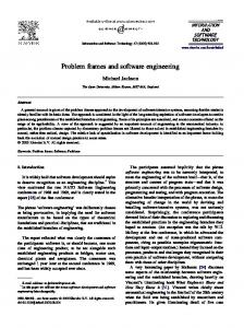
Tab. 4, PF 3.3 commanded transformation: This frame is similar to the simple workpieces frame. The difference is that two lexical domains exist. If these domains can be merged, the simple workpieces frame should be instantiated. A merge is not possible if the lexical domains are of completely different types. An example is a compiler that is configured and parameterized by the developer (biddable domain). It compiles source code (referenced domain 2) into an executable file (constrained domain). The developer must be considered, because the configuration or the parameters influence the quality of the executable file, and operating errors must be considered when the compiler is developed. Tab. 4, PF 3.7 commanded data-based control: This frame covers control problems where a biddable domain and additional stored data influences the behavior of the controlled domain. An example is a heating control, where the temperature depends on user commands, and public holidays stored in a database. When this frame is applied, an additional frame responsible for filling the database is necessary, e.g. simple workpieces, model building (PF 2.4). Figure 10 shows an instantiation of the commanded data-based control frame. The problem is to lower the shutters in an office automatically when the staff members are not present. The working hours and vacation days of the staff members are stored in a data base. At the same time, staff members present in the office must have the possibility to lift or lower the shutters manually. The requirement is R3: According to a preset configuration of a database or manual commands of staff members, the shutter is lifted or lowered. Tab. 4, PF 3.11 commanded model building: Using this frame, the model is initialized according to commands of a biddable domain and information from a causal domain. An example is a user recording a video with a camera. Tab. 4, PF 3.18 multi-user simple workpieces: This frame is an extention of the simple workpieces frame. It should be applied if the biddable domains cannot be merged (e.g., authentic
a
Shutter Control Machine
b
Staff Vacation & Working Hours Database
a
b Staff
R3
c c Shutter a: SDB!{lower, lift} b: STA!{lower, lift} c: SCM!{up, down}
Figure 10: Instantiated commanded data-based control problem frame users and malicious users, as in a problem frame for authentication, see [HHS06]). In multiuser systems, additional concerns (e.g. access control, concurrent access) must be taken into account. An example is computer-supported cooperative work (CSCW), where collaborative working (on a workpiece) is supported by a computer program. Tab. 4, PF 3.21 multi-user commanded behavior: This frame is an extention of the commanded behaviour frame. It should be applied if the biddable domains cannot be merged. In multiuser systems, additional concerns must be taken into account. An example is an access control system. This concludes the enumeration and assessment of problem frames, based on different domain types. All in all, we have identified 8 new problem frames. One of them was assessed to have only mediocre relevance (PF 1.3), whereas the others were assessed to be useful in practice.
5
Related Work
Since problem frames were introduced, the question of how to make use of them and how to adopt such patterns to make them applicable in more specific software development fields (e.g. software architecture, security engineering) animated many researchers. In this section, we mainly consider those research activities that consider variants of the original problem frames by Jackson [Jac01]. Indeed, Jackson’s frames only take into account functional requirements. For non-functional requirements, special problem frames have to be defined, e.g. to express security and usability problems. Hatebur and Heisel [HH05] introduce special problem frames, which constitute patterns for representing security problems. This approach is enhanced in [HHS06]. There, the frames presented in [HH05] are revised and several additional security problem frames are introduced. These frames carefully distinguish between problems and solutions, and, as a consequence, concretized security problem frames are defined to capture known approaches to achieve security. Wentzlaff and Specker [WS06] present HCIFrames, which consider usability requirements in a functional context. Their HCIFrames are linked to already defined HCI design patterns [Tid05, FvWB06] to establish a pattern-based transition from problem analysis to software design.
Also for functional requirements, further useful problem frames have been found. Choppy and Heisel [CH04] define two problem frames tailor-made for information systems, namely the query and the update frames. Some approaches use the problem frame concept not only for problem analysis, but also for other activities in the software development lifecycle. Hall et al. [HJL+ 02] developed AFrames to introduce architectural concepts into problem frames. The original problem frame approach is extended by domains with existing architectural support. In a further publication, Rapanotti et al. [RHJN04] linked AFrames to architectural styles [BMR+ 96] such as Model-View-Controller and Pipe-and-Filter. Lin et al. [LNI+ 03] use the ideas underlying problem frames to define so-called anti-requirements and the corresponding abuse frames. An anti-requirement expresses the intentions of a malicious user, and an abuse frame represents a security threat. The purpose of anti-requirements and abuse frames is to analyze security threats and derive security requirements. The above-mentioned problem frame variants are derived by abstracting frequently occurring problems. In contrast, our approach to detect new problem frames comes from the opposite direction by considering possible problem frames and then checking if there exist enough realistic problems covered by the respective frames.
6
Conclusions and Future Work
In this paper, we have taken a novel path for detecting relevant patterns that support software development, in particular problem frames. To obtain a good selection of new relevant problem frames, we investigated the nature of problem domains and the kind of communication between them in more detail. These investigations and the enumeration approach resulted in the following contributions: • We use new means for characterizing problem domains and their interfaces in more detail. By referring to notational elements of UML, we are in the position to specify more details of problem domains and their interfaces, thus improving the comprehension of problem frames. Our approach extends the meaning of problem frames by pointing out domain characteristics and interface properties for elaborating their basic communication. • We identified a new problem domain type. Our approach provides a better understanding of domain roles and their communication represented by a problem frame. During our in-depth investigations, we identified a new basic problem domain type, namely “display”. Display domains are clearly distinguished from the other domain types introduced by Jackson. • We specified integrity conditions for excluding meaningless problem frames. Taking into account the characteristics of the different domain types, it is possible to identify meaningless problem frames by consideration of their frame diagrams. Such problem frames need not be investigated any further. • We identified 8 new problem frames and gave a short assessment of their applicability. We consider the vast majority of the new problems (7 out of 8) as useful and relevant for realistic software development problems. In the future, we intend to continue our research on problem frames and pattern mining. In particular, we intend to • formalize problem frames to equip them with an unambiguous semantics • find additional integrity conditions for problem frames, possibly based on a formalization • consider more kinds of problem domains, e.g. business domains that represent organizations • consider problem frames with more than one constrained domain • specify merge rules for problem frames development and usage • consider behavioral aspects in problem frames • use the enumeration approach for other kinds of patterns We think that a comprehensive set of problem frames should belong to the “tool box” of every software analyst. Acknowlegement We thank Eduardo B. Fernandez and Tim Wellhausen for their valueable and constructive comments on our work.
References [BMR+ 96] F. Buschmann, R. Meunier, H. Rohnert, P. Sommerlad, and M. Stal. Pattern-Oriented Software Architecture: A System of Patterns. John Wiley & Sons, 1996. [CH04]
C. Choppy and M. Heisel. Une approache a` base de patrons pour la sp´ecification et le d´eveloppement de syst`emes d’information. Approches Formelles dans l’Assistance au D´eveloppement de Logiciels - AFADL, 2004.
[CHH05]
C. Choppy, D. Hatebur, and M. Heisel. Architectural patterns for problem frames. IEE Proceedings – Software, Special Issue on Relating Software Requirements and Architectures, 152(4):198–208, 2005.
[CHH06]
C. Choppy, D. Hatebur, and M. Heisel. Component composition through architectural patterns for problem frames. In Proc. XIII Asia Pacific Software Engineering Conference, pages 27–34. IEEE Computer Society, 2006.
[FJ99]
M. E. Fayad and R. E. Johnson. Domain-Specific Application Frameworks. John Wiley and Sons, 1999.
[For06]
UML Revision Task Force. OMG Unified Modeling Language: Superstructure, April 2006. http://www.omg.org/docs/ptc/06-04-02.pdf.
[Fow97]
M. Fowler. Analysis Patterns: Reusable Object Models. Addison Wesley, 1997.
[FvWB06] E. Folmer, M. van Welie, and J. Bosch. Bridging patterns: An approach to bridge gaps between se and hci. Information and Software Technology, 48(2):69–98, 2006. [GHJV95] E. Gamma, R. Helm, R. Johnson, and J. Vlissides. Design Patterns – Elements of Reusable Object-Oriented Software. Addison Wesley, Reading, 1995. [HH05]
D. Hatebur and M. Heisel. Problem frames and architectures for security problems. In B. A. Gran, R. Winter, and G. Dahll, editors, Proc. 24th Int. Conf. on Computer Safety, Reliability and Security (SAFECOMP), LNCS 3688, pages 390–404. Springer-Verlag, 2005.
[HHS06]
D. Hatebur, M. Heisel, and H. Schmidt. Security engineering using problem frames. In G. M¨uller, editor, Proc. of the International Conference on Emerging Trends in Information and Communication Security (ETRICS), LNCS 3995, pages 238–253. Springer-Verlag, 2006.
[HJL+ 02] J. Hall, M. Jackson, R. Laney, B. Nuseibeh, and L. Rapanotti. Relating software requirements and architectures using problem frames. In Proceedings of the 10th Anniversary IEEE Joint International Conference on Requirements Engineering, pages 137 – 144, Washington, DC, USA, September 2002. IEEE Computer Society Press. [Jac95]
M. Jackson. Software Requirements & Specifications: a Lexicon of Practice, Principles and Prejudices. Addison-Wesley, 1995.
[Jac01]
M. Jackson. Problem Frames. Analyzing and structuring software development problems. Addison-Wesley, 2001.
[JZ95]
M. Jackson and P. Zave. Deriving specifications from requirements: an example. In Proc. 17th Int. Conf. on Software Engineering, Seattle, USA, pages 15–24. ACM Press, 1995.
[LNI+ 03]
L. Lin, B. Nuseibeh, D. Ince, M. Jackson, and J. Moffett. Introducing abuse frames for analysing security requirements. In Proceedings of 11th IEEE International Requirements Engineering Conference (RE’03), pages 371–372, 2003. Poster Paper.
[RHJN04] L. Rapanotti, J. G. Hall, M. Jackson, and B. Nuseibeh. Architecture-driven problem decomposition. In Proceedings of the 12th IEEE International Requirements Engineering Conference (RE’04), Kyoto, Japan, 2004. IEEE Computer Society Press. [SG96]
M. Shaw and D. Garlan. Software Architecture. Perspectives on an Emerging Discipline. Prentice-Hall, 1996.
[SM98]
A. Sutcliffe and N. Maiden. The domain theory for requirements engineering. IEEE Transactions on Software Engineering, 24(3):174–196, 1998.
[Sut02]
A. Sutcliffe. The Domain Theory, Patterns for Knowledge and Software Reuse. Addison Wesley, 2002.
[Tid05]
J. Tidwell. Designing Interfaces. O’Reilly Media, Sebastopol, USA, 2005.
[WS06]
I. Wentzlaff and M. Specker. Pattern-based development of user-friendly web applications. In Proceedings of the 2nd International Workshop on Model-Driven Web Engineering (MDWE 2006), Palo Alto, USA, 2006. ACM.


![A SYSTEMATIC ACCOUNT OF Oscillatoria SPECIES FROM SONVAD ... [PDF]](https://m.moam.info/img/260x300/a-systematic-account-of-oscillatoria-species-from-_647a12bc098a9e61678b45e9.jpg)