Department of Software Engineering, Charles University in Prague, Czech Republic ... conceptual modeling, data semantics, matching algorithms etc. Using a .... For example, there is a format for XML messages with purchase orders sent by ... The WS part covers business processes implemented by the XML system.
A A Framework Framework for for Efficient Efficient Design, Design, and Evolution of a System of and Evolution of a System of XML XML
Maintaining, Maintaining, ? Applications Applications?
Martin Neˇcask´ y, Irena Ml´ ynkov´a Martin Neˇcask´ y and Irena Ml´ ynkov´a Department of Software Engineering, Charles University in Prague, Czech Republic Department of Software Engineering, Charles University in Prague, Czech Republic {necasky,mlynkova}@ksi.mff.cuni.cz {necasky,mlynkova}@ksi.mff.cuni.cz Abstract. The today’s applications usually form a system of sub-applications, each being responsible for a particular functionality. Hence, the design and maintenance of such a complex system is not a simple task. In addition, the user requirements can change and the affected parts need to be identified and evolved. Similarly, new components or even whole system may need to be integrated. In this paper we describe a framework that enables one to face the described issues. For this purpose we exploit verified technologies, such as conceptual modeling, data semantics, matching algorithms etc. Using a set of examples we show that our approach enables one to design, maintain, and evolve a system of applications efficiently and precisely. We depict the features on an XML system represented by a set of web services that exchange XML data. However, the concepts are general and can easily be extended for any kind of data format.
1
Introduction
The current applications are often based on two concepts. First, they do not form a monolithic piece of software, but they are usually composed of a set of simpler sub-applications, each being responsible for a particular execution part. Second, such sub-applications usually exploit a set of web technologies so that they can be distributed and communicate with each other. Hence, we usually speak of a complex system of applications which involves a huge amount of data formats being exchanged and processed by its components. Considering such a complex system, there occurs a number of related issues. First, the data formats need to be designed. With regard to the existing data design techniques we need a kind of conceptual model, general enough to cover any of the formats. Second, we need to design the formats correctly, so that they cover all the required information, but avoid redundancies. Hence, we cannot design the particular formats independently. And, last but not least, when the system is designed and implemented, there occurs the problem of evolution. The requirements of users can change which can lead to changes in several data formats and consequently the respective components that process and exchange ?
ˇ Supported by the Czech Science Foundation (GACR), grants no. 201/09/P364 and P202/10/0573.
J. Pokorn´ y, V. Sn´ aˇsel, K. Richta (Eds.): Dateso 2010, pp. 38–49, ISBN 978-80-7378-116-3.
A Framework for Efficient Design, Maintaining, and Evolution . . .
39
the data. It can also influence storage and manipulation strategies of the data formats. And, similarly, new applications may need to be incorporated, or even whole systems may be mutually integrated. The aim of this paper is to describe a framework that faces the described issues and identifies related problems that have not been solved yet by researchers. The proposed framework covers the whole life cycle of a system of applications from design and maintenance to evolution. Its main advantages are as follows: – It involves a conceptual level of both the data and the business processes which enable one to describe the user requirements easily and precisely. – It creates and preserves the relations between applications and their data. Hence, any evolution change can be propagated to all affected components. – The system is open, thus new applications can be semi-automatically incorporated or it can be integrated with a whole other system. – The additional information are exploited in various parts of the system, such as storage strategies or matching of components during integration. Probably the most common example of the described system is represented by the principle of Service Oriented Architecture (SOA) and its most common implementation – web services [16]. A web service (WS) is a software system designed to support machine-to-machine interaction over the Internet using message exchanging. Most of the functionality of a WS is based on XML [8] – its interface is described in WSDL [11], the data is exchanged using SOAP [9] messages, etc. For simplicity we will consider only such type of system – so-called XML system of applications that exchange and process data in XML format. However, the framework can easily be extended for various other formats. The paper is structured as follows: Section 2 provides a running example of an XML system. Section 3 describes basic decomposition of an XML system and Section 4 describes advanced components that form the framework. Section 5 provides conclusions.
2
Running Example
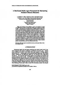
Let us consider a real-life purchasing application, in particular a simple business process of purchasing goods. The diagram of the business process modeled in BPMN [13] is depicted in Figure 1. The process starts with receiving a purchase order from a customer. Firstly, the trader checks the provided credit card details and rejects the purchase when the check fails. Otherwise, the trader arranges delivery of the purchased goods and sends an invoice back to the customer. The business process is implemented by a publicly available WS PurchaseWS depicted in Figure 2. The WS provides an operation ProcessPurchase that receives a purchase order as the input from a customer. When a customer’s credit card cannot be validated the WS sends a rejection message back to the customer. Otherwise, the customer receives an invoice with the delivery details as a response from the WS.
40
Martin Neˇcask´ y, Irena Ml´ ynkov´ a PurchaseWS
CreditCardValidatorWS ValidateCard
UPCShipmentWS
Reject Purchase Check Credit Card
GetShipmentRates
Credit Card O.K.
Receive Purchase
Arrange Delivery
ProcessPurchase
ProcessShipment
Send Invoice Customer
Fig. 1. Purchasing Business Process Diagram
FedExDeliveryWS GetUSRates GetWorldRates ArrangeDelivery
Fig. 2. PurchaseWS WS
Figure 2 also depicts third-party WSs exploited in the implementation of PurchaseWS. CreditCardValidator WS is exploited for validating credit cards of customers. WSs of various logistics companies are exploited. To arrange a shipment, shipment offers are retrieved from these services and the cheapest is selected. The figure depicts WSs of the UPS1 and FedEx2 companies.
3
Basic System Decomposition
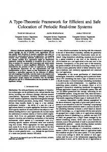
The full architecture of our framework is depicted in Figure 3. In this section we describe so-called run-time parts, i.e. parts that form the run time of an XML system. In the following section we describe extensions we need to design, maintain and evolve such XML system efficiently. The run-time parts of the system are XML Schema part, Web Services part, Database part, and Semantics part. We denote them XS, WS, DB, and SEMANTICS, respectively. The XS component is a mandatory part of each XML system. It covers XML schemas that specify XML formats applied in the system and integrity constraints that enhance XML schemas with advanced conditions that cannot be expressed with XML schema languages. XML schemas can be expressed in languages such as, e.g., XML Schema [5, 6], or Relax NG [25]; for expressing XML constraints, XML pattern languages, e.g. Schematron [19], can be applied. Example 1. The running example in Section 2 exploits several XML formats. For example, there is a format for XML messages with purchase orders sent by customers to PurchaseWS or two formats for XML messages with delivery information sent by PurchaseWS to UPCShipmentWS and FedExDeliveryWS. There are also advanced integrity constraints – for example, an integrity constraint specifying that “check sum equals to the sum of prices of individual items”. 1 2
http://www.ups.com/ http://fedex.com/
A Framework for Efficient Design, Maintaining, and Evolution . . .
41
Figure 2: Run-time and Design-time Components Fig. 3. System Architecture 1. Complex design • WS Motivation: The part covers business processes implemented by the XML system. o XML system comprise many components such that as XML schemas, a A WS is comprehended as can a standalone software component implements WSDL schemas, database schemas, integration scripts etc. However, business process. Data mediators can then implement transformation of XML these components do not provide an overall picture of the whole data messages between WSs, orchestration/choreography allows for composition domain andand business processes as they implement different viewpoints of individual WSs into complex services ones. other Transformations can be specified of various participants (e.g. users, systems, standardization efforts,To etc.). as XSLT [1] scripts. describe orchestration/choreography, languages such as • Solution: WSBPEL [10] can be applied. o Techniques for designing an overall conceptual model of the data
Example 2. In domain our sample system processes we specifywill WS descripand business be interfaces developed. as It isWSDL represented by thePurchaseWS two desing-phase partsthe of the XML systemUPCShipmentWS architecture depictedand in tions. Moreover, exploits two external Figure 2: also two trader’s internal WSs InventoryWS and AcFedExDeliveryWS and DM (Domain Model)ofpart covers a conceptual model the data countingWS for checking the amount a particular product on theofstock and domain. It comprises issuing invoices, respectively. In other words, PurchaseWS orchestrates these • PIM (Platform-Independent Model) which contains WSs. Since the input XMLconceptual formats ofdiagrams both UPCShipmentWS of the data domain.and PIMFedExDelivmodels eryWS differ from the output XML format of PurchaseWS, it necessary important aspects of the data domain (i.e.isconcepts andto relationships) independently its representation at logical incorporate XSLT data mediators that transform theofmessages respectively. levels, i.e. XML and DB. Diagrams can be expressed with
The DB (Database) part covers that persist XML data involved existing UMLdatabases class diagrams. in the system. The XML• documents can be stored centrally in advanced a single database Integrity constraints extend PIM with integrity constraints thatNative can notXML be expressed the PIM or distributed across different databases. databaseswith allow for storing modeling Existing OCL (Objectrequire Constraints XML messages in their native form.language. Object-relational databases decomLanguage) can be exploited. position of XML messages into object-relational tables.
BPM (Business Process Model) part covers a conceptual model
business processes. It comprises Example 3. The dataofinthe the exchanged XML messages in our sample XML system are stored in a relational database. When a purchase order arrives from a customer, it is shredded into records of relational tables. The same is for other information, e.g. delivery details, invoices etc. Conversely, because of legal constraints, each trader needs to store the invoices from suppliers as they come instead of converting them to normalized relational tables. Therefore, the trader exploits a native XML database in this case.
42
Martin Neˇcask´ y, Irena Ml´ ynkov´ a
The SEMANTICS part exploits ontologies to express semantics of the data domain and business processes in a machine-readable way. Domain ontologies specify semantics of the data domain, e.g., in OWL [3]. Process ontologies specify semantics of business processes, e.g., in OWL-S [2] or WSMO [7]. This enables one to exploit various advanced semantic techniques to, e.g., dynamically discover PurchaseWS or mediate other business processes to the business process implemented by the XML system. Example 4. For customers equipped with solutions based on the Semantic Web technologies, a trader can provide additional semantics part of the XML system. The trader exploits a standardized BMO3 business ontology to specify the important concepts, e.g. customer, product, purchase etc., and the purchasing business process at the semantic level. When two or more run-time parts are present in the system, we need them to work together. This internal integration is covered by integration parts called XML VIEWS, SEMANTIC VIEWS, XML GROUNDING, and WS GROUNDING depicted in Figure 3 as double-colored rounded boxes. XML VIEWS cover integration of the XML and DB parts. They transform data from its database representation to XML representation and vice versa. An XML view can be expressed in XML query languages such as SQL/XML [18]. Example 5. In our example we need XML views expressed in SQL/XML to transform the data stored in the relational database (e.g. purchase orders and delivery data) to XML formats specified by the XML schemas in the XS part and vice versa. These views allow to access the data in their various XML representations even if it is logically stored in relational tables. SEMANTIC VIEWS cover integration of SEMANTICS and DB parts. They transform data from its database representation to the ontological representation, e.g. RDF [4] triples, and vice versa. This allows for expressing the semantics of the data in a machine-readable way and, at the same time, database-supported semantic reasoning and querying. A SEMANTIC view can be expressed in an XML query language, such as SQL/XML, as RDF triples can be represented in XML. Example 6. Our sample system provides semantics-enabled customers with the purchase, invoice, and delivery data represented in the ontological representation conforming to the ontologies from the SEMANTICS part. This is achieved by semantic views that convert, e.g., purchase order data in relational tables to RDF triples and vice versa. XML GROUNDING integrates SEMANTICS and XS parts. It comprises mutual mappings of XML schemas to domain ontologies and as XSLT scripts that specify data transformation between XML and ontological representation. It is similar to SEMANTIC VIEWS part but instead of DB there is the XS part. 3
http://www.bpiresearch.com/Resources/RE_OSSOnt/re_ossont.htm
A Framework for Efficient Design, Maintaining, and Evolution . . .
43
Example 7. When a semantics-enabled customer receives an XML message with delivery information, (s)he needs to know the semantics of parts of the XML message, e.g. delivery date, packaging etc., in the terms of the domain ontology. This is expressed by the XML grounding that provides mapping of parts of the XML schema for the XML message to the domain ontology. WS GROUNDING integrates SEMANTICS and WS parts. It enhances XML GROUNDING by adding mappings of WS operations, orchestration, and choreography to process ontologies in order to specify semantics of, e.g., inputs/outputs of WSs. Example 8. Similarly to XML grounding, it is necessary to provide mapping of the WSDL description of PurchaseWS to the process ontology that specifies the semantics of our purchasing business process.
4
System Extensions
The components described in the previous section (or, in simpler cases, their various subsets) form the XML system and are present at run time. They need to be designed, implemented, and maintained. In addition, since an XML system usually evolves, the components need to be modified or even whole new XML components need to be integrated. Our framework involves techniques and tools that enable one to manage the whole life cycle of an XML system in a userfriendly and effective way. Complex Design As we have outlined, an XML system involves XML schemas, WSDL schemas, database schemas, integration scripts etc. They implement different and often limited viewpoints of various participants (i.e. users, other systems, standardization efforts etc.). Therefore the primary component of the extended system is a family of conceptual models [27], related integrity constraints [31], and a complex design tool [12] that supports them. In Figure 3 they are represented by the two design-phase parts of the architecture – DM and BPM. The DM (Domain Model) part covers a conceptual model of the data domain. It involves platform-independent model (PIM ) which provides conceptual diagrams of the domain and integrity constraints. PIM models important aspects of the data domain (i.e. concepts and relationships) regardless its representation at logical levels, e.g. XML or DB, using classical UML [15] class diagrams. Integrity constraints extend PIM with information that cannot be expressed with the PIM modeling language. For this purpose (OCL) [14] is exploited. Example 9. Figure 4 depicts a PIM diagram4 of our sample problem domain. Concepts are expressed as classes, e.g. Customer or Order. Relationships between concepts are expressed as associations. 4
It was modeled in XCase [12], a modelling tool that implements basic features described in this paper.
44
Martin Neˇcask´ y, Irena Ml´ ynkov´ a
Fig. 4. DM PIM Fig. 5. DM PSM
The BPM (Business Process Model) part covers a conceptual model of the business processes. It involves PIM which provides conceptual diagrams of the business processes and integrity constraints. PIM models activities, events, and messages participating in business processes independently of their implementation in WS part in BPMN [13]. Integrity constraints extend PIM with advanced constraints specific for individual WSs (e.g. pre-conditions and post-conditions of activities and events or constraints on exchanged messages). Again OCL can be applied. Example 10. A sample business process PIM diagram is depicted in Figure 1. Each message, e.g. purchase order, credit-card check, invoice etc., specified by the business process represents part of the data domain. This part is modeled as a PIM diagram which is part of the whole PIM diagram from Figure 4. For example, the PIM diagram for invoice messages contains Order, ProductItem, Product, and Customer classes. Note that the existing modeling languages [15, 13] consider data modeling and business-process modeling separately. In our framework we interconnect these two areas and model them uniformly at PIM level. Hence, PIM gives an overall picture of the data domain and business processes independently of their implementation; the interconnection enables one to describe the required applications more precisely. We survey methods for conceptual modeling techniques in [26], where we show that current methods allow modeling XML formats only at the PSM level. In [27] we introduced a conceptual model for XML that allows for modeling XML formats also at the PIM level. Regarding business process modeling, there are languages such as BPMN [13]. However, we are missing methods for modeling data in current BPM PIM modeling languages, i.e. methods interconnecting BPM and DM PIMs. These languages must therefore be further extended. Probably the first step towards this aim is paper [21], where the authors deal with transformations of BPM to UML using XSLT.
A Framework for Efficient Design, Maintaining, and Evolution . . .
45
Forward Engineering Manual coding of all components of the XML system (e.g. XML and WSDL schemas, XSLT scripts, database schemas etc.) consumes a lot of effort and is error-prone. Hence, our framework is based on a family of conceptual models [27] and respective technologies. Apart from PIM, it involves so-called platform-specific model (PSM ) represented by the XML PSM integration part, where each diagram takes part of the PIM diagram(s) and specifies how it is represented in a particular XML format. The diagram can also be comprehended as a mapping between PIM and XML schemas. Similarly, our framework involves techniques for specification of implementation of the business processes by WSs. This is represented by the WS PSM integration part and comprises WS PSM diagrams. Again each diagram specifies implementation of parts of a business process.5 The translation of PSMs to respective representations is done semi-automatically. In particular it involves translation of: – XML PSM to XML schemas (DM-to-XS ), – XML PSM to database schemas (DM-to-DB ) and XML VIEWS, – WS PSM to WSDL descriptions, XSLT data mediation scripts, BPEL orchestrations, and WS-CDL choreographies (BPM-to-WS ), and – PIM to ontologies (DM&BPM-to-SEMANTICS ) and SEMANTIC VIEWS. Forward engineering is depicted in Figure 3 by white-filled arrows. Example 11. A sample XML PSM diagram is depicted in Figure 5. It models how invoices are implemented in XML, i.e. how instances of classes from the DM PIM diagram in Figure 4, e.g. Order, Customer, or Product, are represented. From the XML PSM diagram, an XML schema, XML view, and XML grounding for this particular XML format are derived. Similarly, forward engineering of BPM PIM to WSs specification can be solved via BPM PSM. Consequently, the manual coding of WS, XML, DB, and SEMANTICS parts components is significantly reduced to design of XML PSM and WS PSM diagrams which is more user-friendly and natural. The user does not need to bother with syntactic details, specifics of particular format etc. What is more, the common PIM diagram also formally interrelates components of WS, XML, DB, and SEMANTICS run-time parts. Such information is further exploited in the following sections. In [26], we also study techniques of translating conceptual diagrams in various conceptual modeling languages to XML schemas. There are also methods for translating BPMN diagrams to BPEL scripts [34]. The translation is done only automatically. However, designers need a possibility to influence the translation process which is missing in the current literature. In [29], we study derivation of an optimal native XML database schema from a set of XML PSM diagrams and their DM PIM diagram. In [33], the authors 5
Note that in the same way the system can be extended with PSM of relational data (e.g. ER diagrams [32]), classes and objects (e.g. UML [15]), etc.
46
Martin Neˇcask´ y, Irena Ml´ ynkov´ a
study methods of derivation of an optimal hybrid database schema for a given XML schema. These methods should be further extended for deriving a hybrid database schema for a set of XML PSM diagrams. Reverse Engineering When a new XML component needs to be incorporated into the XML system, it is usually necessary to integrate it with other components manually. In simple cases it is possible, however in complex situations it can be a very hard task. For this purpose our framework involves (semi-)automatic techniques for reverse engineering of: – XML schemas to XML PSM diagrams – WS components (i.e. WSDL schemas, BPEL, and WS-CDL scripts) to WS PSM diagrams – external domain ontologies to DM PIM, and – external process ontologies to BPM PIM. Example 12. Suppose that the trader wants the XML system to support also managing supplies from the suppliers. The suppliers provide WSs for managing supplies; however, the interfaces are different. This requires to integrate the WSDL descriptions and XML schemas of the suppliers with the trader’s XML system. Instead of doing this manually, we enable one to map the XML schemas to the DM PIM diagram through XML PSM diagrams (semi-)automatically derived from the XML schemas. WSDL descriptions can be also mapped in a similar way to a BPM PIM diagram specifying the supply management business process from the trader’s point of view. Then, all other components can be derived automatically using the forward engineering procedures. Having the (semi-)automatic strategy, we significantly reduce the manual work when incorporating third-party components, e.g. XML schemas, WSDL descriptions, or ontologies of standardization organizations, business partners etc., into an existing XML system. As we have described in [28] the reverse engineering approach cannot be purely automatic since in several cases there can be multiple options of a suitable mapping. However, using verified strategies, such as similarity matching [23], evaluation of semantics etc., our approach enables one to reduce the options to reasonable amount. In addition, it even provides several metrics that enable one to evaluate quality of the options from distinct points of view. Note that similarly we can support integration of whole XML systems at PIM level. Again, if a given system does not involve our DM and BPM extensions, they can be reverse engineered. Then the PIM integration specifications are directly translated to XSLT data mediators and BPEL business process mediators. Evolution and Versioning Management As mentioned before, sooner or later user requirements can change and, hence, the respective data need to be modified. The problem is that such modifications can affect multiple components of the system, such as, e.g., XML schemas, WSDL descriptions, database schemas
A Framework for Efficient Design, Maintaining, and Evolution . . .
47
etc. And not only can such modifications be demanding, but, in complex systems, they can also be very hard to identify. For the purpose of complex evolution management we exploit the previously described features described. Similarly to design phase, we assume that most users express their modifications in PIM since again (s)he does not have to bother with specific features of particular formats. Such changes are then propagated to all related run-time parts by exploiting the forward-engineering methods – we speak about downwards propagation. On the other hand, when a change needs to be done in a run-time part, it can be propagated to PIM by exploiting the reverse-engineering methods – we speak about upwards propagation – and then to all the related system parts again using downward propagation [30]. To perform the respective modifications, our framework involves techniques for (semi-)automatic derivation of XSLT scripts. Example 13. In our sample scenario, we may need to represent names of customers in purchase orders as a pair first name and surname instead of a single value name. This requires to modify the XML schema for purchase orders. It may need to be propagated to the existing XML messages to preserve validity against the evolved XML schema as well as to the corresponding XML PSM diagram to preserve consistency with the XML schema. However, this also requires to change the DM PIM diagram or mapping from the XML PSM diagram to the PIM diagram. When the DM PIM diagram is changed, the change must be propagated downward to the other XML schemas in the system. Similarly to the case of reverse engineering, also in case of evolution management the key advantage of our approach is reduction of manual work when the XML system evolves. As we have studied in [30], the amount of approaches to XML evolution is surprisingly low and the approaches are trivial. They only deal with separate aspects, such as propagation of modification of XML schema level to XML documents or vice versa [22], several papers also deal with modifications of a kind of abstraction of the XML schema – either visualization [20] or UML diagram [17], i.e. a kind of PSM. However, none of them views the problem from the point of view of multiple applications sharing common domain. Run-Time Support During the run time of the system we need further system components, such as storage strategies and respective query operations, platform for running WSs, support for semantic operations etc. All these components can also benefit from the design-time components and exploit the complex information on the whole system at run time. For example, in most XML systems the XML data that are processed and exchanged by its components usually need to be persistently stored and retrieved. In general, there seems to be no generally optimal storage strategy. Since requirements of various XML applications significantly differ, for each type of processing of XML data the respective appropriate approach should be used [24]. And it is even often further optimized in a specific way. However, manual optimization of,
48
Martin Neˇcask´ y, Irena Ml´ ynkov´ a
e.g., database schemas with respect to the expected data retrieval and manipulation is complicated task. The more information are taken into account, the better, however the more complicated the search for optimum becomes. As we have already described, our framework involves complex information on multiple applications that process the XML data, data mediators, schema versions etc. Consequently, the respective storage strategies can be found more precisely and in more broader context of multiple application views. In addition, they can be adjusted to centralized or distributed architecture.
5
Conclusion
The aim of this paper was a description of a framework that enables one to simplify, clarify, and streamline the design, maintenance, and evolution of a complex system of applications. Due to space limitations we have described a general architecture of an XML system, the most common issues that need to be solved during its life cycle and, in particular, how they can be simplified using the described framework, i.e. extension of the system. Our current work naturally covers the full implementation of the key components of the framework. Some of them have already been covered by XCase [12] which we currently extend with modeling of business processes and storage level. Our future work will focus mainly on support of non-XML data models such as ER model, UML, etc. and application of the system in real-world use cases.
References 1. XSL Transformations (XSLT) Version 1.0. W3C, 1999. http://www.w3.org/TR/ xslt. 2. OWL-S: Semantic Markup for Web Services. W3C, 2004. http://www.w3.org/ Submission/OWL-S/. 3. OWL Web Ontology Language. W3C, 2004. http://www.w3.org/TR/ owl-features/. 4. RDF/XML Syntax Specification (Revised). W3C, 2004. http://www.w3.org/TR/ rdf-syntax-grammar/. 5. XML Schema Part 1: Structures (Second Edition). W3C, 2004. http://www.w3. org/TR/xmlschema-1/. 6. XML Schema Part 2: Datatypes (Second Edition). W3C, 2004. http://www.w3. org/TR/xmlschema-2/. 7. Web Service Modeling Ontology (WSMO). W3C, 2005. http://www.w3.org/ Submission/WSMO/. 8. Extensible Markup Language (XML) 1.0 (Fourth Edition). W3C, 2006. http: //www.w3.org/XML/. 9. SOAP Version 1.2 Part 0: Primer. W3C, 2007. http://www.w3.org/TR/soap12-part0/. 10. Web Services Business Process Execution Language (WSBPEL) TC. OASIS, 2007. http://www.oasis-open.org/committees/tc_home.php?wg_abbrev=wsbpel. 11. Web Services Description Language (WSDL) Version 2.0 Part 0: Primer. W3C, 2007. http://www.w3.org/TR/wsdl20-primer/.
A Framework for Efficient Design, Maintaining, and Evolution . . .
49
12. XCase – A Tool for XML Data Modeling. 2008. http://kocour.ms.mff.cuni.cz/ ~necasky/xcase/. 13. Documents Associated with Business Process Modeling Notation (BPMN) 1.2. OMG, 2009. http://www.omg.org/spec/BPMN/1.2/. 14. Object Constraint Language Specification, version 2.0. OMG, 2009. http://www. omg.org/technology/documents/formal/ocl.htm. 15. Unified Modeling Language. OMG, 2009. http://www.uml.org/. 16. Web Services Activity. W3C, 2009. http://www.w3.org/2002/ws/. 17. E. Dominguez, J. Lloret, A. L. Rubio, and M. A. Zapata. Evolving XML Schemas and Documents Using UML Class Diagrams. In DEXA’05, pages 343–352, Berlin, Heidelberg, 2005. Springer. 18. ISO/IEC 9075-14:2003. Part 14: XML-Related Specifications (SQL/XML). Int. Organization for Standardization, 2006. 19. R. Jelliffe. The Schematron – An XML Structure Validation Language using Patterns in Trees. 2001. http://xml.ascc.net/resource/schematron/. 20. M. Klettke. Conceptual XML Schema Evolution – the CoDEX Approach for Design and Redesign. In BTW Workshops, pages 53–63. Aachen, 2007. 21. O. Macek and K. Richta. The BPM to UML Activity Diagram Transformation Using XSLT. In DATESO’09, volume 471, pages 119–129, Spindleruv Mlyn, Czech Republic, 2009. CEUR-WS. 22. M. Mesiti, R. Celle, M. A. Sorrenti, and G. Guerrini. X-Evolution: A System for XML Schema Evolution and Document Adaptation. In EDBT’06, pages 1143– 1146, Berlin, Heidelberg, 2006. Springer. 23. I. Mlynkova. Similarity of XML Schema Definitions. In DocEng’08, pages 187–190, 2008. 24. I. Mlynkova. Standing on the Shoulders of Ants: Towards More Efficient XML-toRelational Mapping Strategies. In XANTEC’08, pages 279–283, Turin, Italy, 2008. IEEE. 25. M. Murata. RELAX (Regular Language Description for XML). 2002. http: //www.xml.gr.jp/relax/. 26. M. Necasky. Conceptual Modeling for XML: A Survey. In DATESO’06, volume 176, pages 40––53, Cerna Ricka, Czech Republic, 2006. CEUR-WS. 27. M. Necasky. Conceptual Modeling for XML. IOS Press, Heidelberg, Netherlands, 2008. 28. M. Necasky. Reverse Engineering of XML Schemas to Conceptual Diagrams. In APCCM’09, pages 117––128, Wellington, New Zealand, 2009. CRPIT. 29. M. Necasky and T. Knap. Reconstruction of Normalized XML Documents. In Innovations’08, pages 213––217, Al Ain, UAE, 2008. IEEE. 30. M. Necasky and I. Mlynkova. On Different Perspectives of XML Schema Evolution. In FlexDBIST’09, Linz, Austria, 2009. IEEE. 31. M. Necasky and K. Opocenska. Designing and Maintaining XML Integrity Constraints. In MoViX’09, Linz, Austria, 2009. IEEE. 32. Ch. Peter. Entity-Relationship Modeling: Historical Events, Future Trends, and Lessons Learned. pages 296–310, 2002. 33. L. Stromback, M. Asberg, and D. Hall. HShreX — a Tool for Design and Evaluation of Hybrid XML Storage. In FlexDBIST’09, Linz, Austria, 2009. IEEE. 34. S. A. White. Using BPMN to Model a BPEL Process. IBM Corp., USA, 2005. http://bpmn.org/Documents/Mappingf.