A fully programmable Rake-receiver architecture for multi-standard baseband processors Anders Nilsson, Eric Tell, Dake Liu Department of Electrical Engineering Linkoping University Linkoping, Sweden andni,erite,
[email protected] ABSTRACT Programmability will be increasingly important in future multi-standard radio systems. We are presenting a fully programmable and flexible DSP platform capable of efficiently performing channel estimation and Maximum Ratio Combining (MRC) based channel equalization for a large number of wireless transmission systems in software. Our processor is based on a programmable DSP processor with SIMD-computing clusters. We also map Rake receiver kernel functions supporting a large number of common Wireless LAN and 3G standards to this microarchitecture. The use of the inherit flexibility for future standards is also discussed. Benchmarking show that with the proposed instruction set architecture, our architecture can support channel estimation, equalization and decoding of: WCDMA (FDD/TDD-modes), TD-SCDMA and the higher data rates of IEEE 802.11b (CCK) at clock frequency not exceeding 76 MHz. KEY WORDS CDMA, Rake, MRC, DSP, SDR
1 Introduction The ever changing wireless network industry requires flexible and versatile baseband processors to be able to quickly adapt to new and updated standards. This requires programmable baseband processors in order to support multiple radio standards, since a pure ASIC solution will not be flexible enough. ASIC solutions for multi-standard baseband processors are also less area efficient than their programmable counterparts since processing resources cannot be efficiently shared between different operations. In this paper we present a micro-architecture which combines several SIMD computing clusters into a processor core. (Clustered SIMD) Unlike other flexible Rake architectures [2], this architecture will run both the multi-path search, Rake fingers and Maximum Ratio Combining (MRC) in software. A clustered SIMD machine is defined as a processor core with several heterogeneous SIMD-data path clusters (i.e. a 4-way ALU and a separate 4-way CMAC). In a clustered SIMD micro-architecture, only one instruction is issued every clock cycle. Unlike VLIW-
machines, this micro-architecture will allow concurrent vector operations and control flow instructions without the drawbacks and memory usage of a pure VLIW machine. The combination of SIMD units and an efficient memory architecture allows us to drastically improve the processing parallelism without adding extra complexity of VLIW machines. We have chosen to map channel estimation and correction of the following communication standards to our architecture: Standard WCDMA WCDMA-TDD TD-SCDMA IEEE 802.11b
Modulation CDMA/FDD CDMA/TDD CDMA/TDD DSSS/CCK
Type 3G 3G 3G Wireless LAN
Our processor architecture is proven by mapping the most demanding algorithms to the architecture. We both include Frequency Division Duplex (FDD) and Time Division Duplex (TDD) CDMA-modes[1][4] in order to fully prove the architecture. Time Division Duplex mode is the most demanding mode since it requires very short computing latency on the channel estimation compared to the FDD mode where a pilot channel is transmitted simultaneously with the data channel. By proving the TDD mode, we can ensure architectural support for the less demanding modes. The paper is organized as follows. In section 2, we survey four different communication standards and provide an overview Rake based channel equalization. In section 3, we discuss the proposed architecture. Then in section 4 SIMD clusters are discussed. In section 7 scheduling is discussed. In section 8 our results are presented. Finally conclusions are drawn in section 9.
2 Background 2.1 Survey of communication standards The chip rate, the over-sampling rate (OSR) and the required sampling rate for the investigated standards are presented in the following table:
Standard IEEE 802.11b-DSSS IEEE 802.11b-CCK WCDMA-FDD/TDD TD-SCDMA
Chip rate 11 Mcps 11 Mcps 3.84 Mcps 1.28 Mcps
OSR 2 2 4 4
Sample rate 22 MHz 22 MHz 15.36 MHz 5.12 MHz
By using an OSR of 4 for WCDMA/TD-SCDMA, the multi-path searcher will provide sub-chip resolution without fractional delay filters.
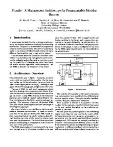
2.2 Rake based channel equalization Rake receivers are often used in CDMA systems to cancel inter-symbol interference resulting from multi-path propagation and to utilize the multi-path diversity. The idea of a Rake receiver is to identify a number of different multi-path components and align them constructively, both in time and phase, thus utilizing the created multi-path diversity. The combination of the different components is performed by Maximum-Ratio Combining (MRC). The function of delaying a certain transmission path and correct its phase is often referred to as a “Rake finger”. A Rake finger is illustrated in Figure 1, and the principle of a Rake receiver is presented in Figure 2. Spreading sequence
τ
Input
Channel estimate To sum
dt
Channel estimate
Figure 1. Rake finger.
Code generator 1 i Sample input Memory Symbol Acc. Memory controller
Acc
Matched Filter & Pilot sequence generator
2.3 Flexibility requirement In 3G standards (WCDMA/TD-SCDMA) de-spreading is accomplished by first de-scrambling the data by a scrambling sequence (Gold code), then by separating each data channel by multiplication with an Orthogonal Variable Spreading Factor (OVSF) code. User data rates can be varied by either reducing the spreading factor or by assigning multiple OVSF codes to a user. Traditional Rake receivers are usually implemented as pure ASIC solutions or as rigid accelerators to processor cores. However, this diversity among CDMA based standards including multi-code transmission requires large flexibility in the receiver. In contrast, conventional Rake-receivers despread each of the multi-path components by a single compound code. This obstructs the use of multi-code transmission. However, by reordering the operations performed in a Rake receiver and running them in a programmable environment, it is possible to facilitate multi-code de-spread without any significant hardware overhead. In the CDMA based Wireless LAN systems such as IEEE 802.11b[7], data symbols are either spread by a sequence having good auto correlation function, or modulated by Complementary Code Keying (CCK). In this case the Rake receiver only performs MRC on chip level.
2.4 Multi-path search Channel estimation can be divided into several tasks: Packet/Frame detection, multi-path search and symbol synchronization. Multi-path search is performed by using matched filters. However the diversity of the different standards render fixed matched filters inefficient. Since transmission delays for the different multi-path components can be large (greater than a number of symbol times), the channel estimator must not only search for synchronization on chip level, it must also search for symbol synch on all multi-paths. In our processor the multi-path search is completely performed by software running on a 4-way complex ALU and a 2-way complex multiplication and accumulation (CMAC) unit. The hardware micro-architecture is discussed in section 4.
3 Architecture overview Ch. estimate
Received symbol
Figure 2. Principle of a Rake receiver.
The number of Rake fingers needed is determined by the multi-path environment. In a Rayleigh fading outdoor environment (ITU Pedestrian B) [3] up to 93% of the scattered energy could be utilized by a four finger Rake.
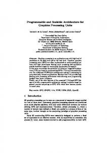
The processor is constructed as a DSP processor with multiple SIMD-execution units. The data paths are grouped together into SIMD clusters. Each cluster has it’s own load/store unit and vector controller. The clusters can execute different tasks while every data path within a cluster performs a single instruction on multiple data. The processor architecture is illustrated in Figure 3. The processor core consists of five main blocks: • A 4-way complex ALU. • A 2-way CMAC.
Memory sub−system
Interface unit
Sample Memory
Analog Front−End
AGU
Sample Memory
Integer Memory
Partial interconnect network
VLU (ALU) ACC
(ALU) ACC
(ALU) ACC
(ALU) ACC
Vector controller
Complex radix−2 data path (2 x CMAC)
RF Vector controller ALSU
MAC
VSU ALU SIMD Data path
CMAC SIMD Data path
Controller unit
Figure 3. Processor micro-architecture
• A memory sub-system with address generators. • A RISC-type controller. • A partial interconnect network. The SIMD units are the 4-way complex ALU, and the 2way complex MAC. The main difference between this processor and a VLIW processor is the instruction issue process. By only allowing one instruction issue per clock cycle, excessive hardware could be saved. The SIMD clusters can simultaneously run independent tasks. When a task is finished, data are transfered between the SIMD units and the processor core by a memory swap[5]. Hence costly memory moves are avoided. Memory management is further discussed in section 5.
3.1 Instruction set The instruction set architecture of the processor consists of three classes of compound instructions. 1. RISC instructions, operating on 16 bit integers. 2. DSP instructions, operating on complex numbers.
backward dependencies between tasks. This allows different tasks to be performed in parallel on SIMD execution units. However, these tasks normally operate on large data sets, such as de-scramble or de-spread of a whole memory block. Instead of using a VLIW-scheme, this property of baseband processing is used in the design of the instruction set architecture. To reduce the complexity and improve the efficency of the control path, only one instruction can be issued every clock cycle. However since vector (SIMD) instructions run on long vectors, many RISC instructions can be executed during the vector operation. This is illustrated in Figure 4.
Time [CC]
Vector instr.
RISC instr. Code example
CMAC
ALU
Control CVL.256 AR0,A++,B++ ADD4.64 AL0,M1,M2 SUBI R0,#2 ... ADD,R2,R3,R5 ... ... ...
3. Vector instructions, running vector operations on a particular SIMD-cluster. The RISC-instruction class contains most control oriented instructions and this instruction class is executed on the controller unit of the processor. (Control ALSU and MACunit). The DSP-instructions operate on complex-valued data and are executed on one of the SIMD-clusters. Vector instructions are extensions of the DSP instructions since they operate on large data-sets and utilize advanced addressing modes and vector loop support.
3.2 Instruction issue Analysis of baseband algorithms shows that the receiving algorithm can be decomposed into task-chains with little
Figure 4. Instruction issue.
Unlike VLIW-machines, our architecture will allow concurrent vector operations and control flow instructions without the drawbacks and memory usage of a pure VLIW machine.
3.3 Task synchronization In a micro-architecture containing several vector execution units, data synchronization is important. In our architecture, we provide special instructions for control flow synchronization. As shown in Figure 4, several vector operations can be executed in parallel. By using idle instructions, the control flow can be halted until a certain vector operation is completed.
Re
Im Vector load unit
"1"
Im −Im Re Re "0"
"0"
4 SIMD processing clusters
"0"
Cin_re
Cin_im
GUARD
This processor contains three execution units: the controller unit and two SIMD clusters. Common to the two SIMD computing clusters are the Vector controller and Vector load/store unit. (VLU/VSU). The VLU is the interface towards the memory blocks and the network interface. The VLU can load data in two different ways. In one mode, multiple data items are loaded each clock cyckle from a bank of memories. In the other mode, data are loaded one item at a time and then distributed to the SIMD-data paths in the cluster. This later mode is used to reduce the number of memory accesses when consecutive data are processed by the SIMD cluster.
"0"
GUARD
Vector store unit RE_ACC
IM_ACC
Figure 5. Part of vector ALU data path micro-architecture
5 Memory sub-system 4.1 Vector-ALU unit The complex vector ALU along with address and code generators are the main components used for Rake finger processing. By implementing a 4-way complex ALU unit with an accumulator, we can perform either four parallel correlations or de-spread four different codes at the same time. These operations are enabled by adding a “short” complex multiplier capable of only multiply by {0, ±1; 0, ±i}. The short complex multiplier can be controlled from either the instruction word, a de-scrambling code generator or from a OVSF code generator. All subunits are controlled from a vector controller which manages load and store order, code generation and hardware loop counting. To relax the memory interface, a special vector load/store unit is employed. The VLU/VSU contains registers to reduce the number of memory data fetches over the network. If a consecutive data items are processed the load unit can reduce the number of memory fetches by 3/4. A part of the micro-architecture of the Vector ALU is shown in Figure 5.
4.2 Vector-CMAC unit The control and load/store structures for the vector CMAC unit are identical to the control structures of the Vector ALU. The vector CMAC contains two full complex data paths which can be run separately or together as a Radix-2 FFT butterfly. [6]
Memory management and allocation are critical in order to efficiently use SIMD architectures. The data memory consists of several small memory blocks with its associated Address Generator Unit (AGU). These memories are in turn connected to a partial interconnect network[5] where they can be connected to several different computing engine ports. The memory sub-system design can be divided into two different areas, address generation for Rake finger processing and data movement architecture.
5.1 Rake finger addressing The length of memory buffers used for delay equalization is determined by the maximum delay-spread (∆t), the chiprate (1/Tc) and the OSR. The minimum memory length is: N = ∆t ·
OSR Tc
N = 184 when ∆t = 12µs[3], OSR=4 and 1/Tc = 3.84 Mcps. Delay equalization in the Rake fingers is performed by using a circular memory buffer and a number of configurable address generators. Each physical memory contains it’s own address generator capable of performing modulo addressing and FFT addressing. Only one memory is used by all Rake fingers. This memory serves as a circular buffer where one sample is written and four samples are read for each input sample. To reduce the complexity of the memory architecture, the memory accesses are time interleaved. For WCDMA Rake finger processing the memory access rate is:
6 Functional mapping
Memory access controller Write AGU
AGU #1
AGU #2
AGU #3
AGU #4
The four main kernel functions performed by a rake receiver are: 1. Delay equalization.
Memory array Read/Write logic
2. Multi-Path search. 3. De-scramble and de-spread.
Figure 6. Memory addressing system for Rake fingers 4. Maximum Ratio Combining. Access rate=
OSR·(1+Nf ) Tc
= 76.8 [Mop/s]
Where Nf = 4 is the number of Rake fingers. The use of a circular memory buffer with configurable address generators allows us to handle transmission delays many times greater than one symbol time. The maximum transmission delay which is acceptable is only limited by memory length.
By separating the de-scrambling (using Gold codes) operation from the de-spread operation (using OVSF codes), the same hardware can be re-used between operations in WCDMA and TD-SCDMA systems. The mapping of the Rake finger functionality to hardware blocks is shown in Figure 8. First the 4-way complex ALU unit are used to de-scramble the received data. By later feeding each accumulator with the corresponding OVSF-code the architecture can run de-spread on four simultaneous OVSF codes. Scrambling code
Channel estimate
5.2 Data movement architecture
Input
In a clustered SIMD processor it is important to have an efficient data movement mechanism to transport data between computing clusters. In our micro-architecture we use memories connected to a partial network. These memories can be connected to different ports on the different computing clusters. Since it is not necessary to connect all memories to all computing elements, the network is optimized to only allow certain memory configurations, hence “partial network”. In order to transfer data between these partial networks, several memory blocks are assigned to both sub-networks. These memory blocks are used as ping-pong buffers between tasks. They are illustrated in Figure 7. Costly memory moves are avoided by “swapping” memory blocks between computing elements. This strategy provides an efficient and predictable data flow without costly memory move operations.
τ Circular buffer AGU
OVSF code
Channel estimate
dt
Complex ALU
... Σ
Complex ALU CMAC
Figure 8. WCDMA Rake mapping.
The channel estimation task is also mapped to the same SIMD units as the Rake finger processing. Correlation with the spreading/pilot sequence is performed by the Complex ALU, whereas peak detection and absolute maximum search is performed by the CMAC unit.
7 Scheduling
Connected to both sub−networks MEM1
MEM2
MEM3
MEM4
MEM5
Partial network #1 Partial network #2
Figure 7. Ping-Pong memory blocks.
In packet based systems such as IEEE802.11b, the frame is so large that it cannot be stored entirely in memory. This requires the channel estimation process to be completed before the reception of the payload data. As a result of this, the required processing performance is huge during the preamble stage. This is illustrated in Figure 9. The processor architecture must have a peak performance matching the worst case computational load encountered. In this case all hardware resources are allocated to the channel estimation process during the preamble. However, in WCDMA systems, channel estimation can be performed at the same time as the reception of data since a pilot channel is always transmitted.
MIPS Cost Channel estimation / Multipath search Channel estimate required here! Payload processing and channel tracking
Frame detection
Time
Figure 9. Worst case scheduling, IEEE802.11b
Furthermore, the communication network and memory resources are statically scheduled in order to reduce the complexity of the memory architecture while maintaining a predictable worst case timing. To achieve optimal resource utilization, the number of computing elements is balanced between SIMD clusters so that each subtask consumes approximately the same number of clock cycles.
7.1 Power considerations The processor architecture is designed with low power techniques in mind. The control paths are minimized due to the inherit control locality of the CSIMD architecture. Furthermore, single port memories are used to reduce the power consumption due to memory accesses. Also, when an execution unit is not used, it’s inputs are masked to reduce unnecessary activity on internal logic.
The main focus of this paper has been on a flexible and efficient micro-architecture capable of performing MRCbased channel equalization for common and future CDMA based communication standards in software. We have presented a system architecture, a memory sub-system and we have mapped Rake kernel functions to this architecture. The kernel functions used by Rake receiving algorithms are benchmarked on the hardware and the result is listed below. Benchmarks illustrate the following cycle cost for different Rake kernel functions: Length 64 16 256 256·2 64 64·4
Required operating frequency 76 MHz 76 MHz 65 MHz 72 MHz
As shown in the table above, this architecture is capable of performing all kernel functions associated with a rake receiver for the standards discussed at a clock rate not exceeding 76 MHz. This limit is given by the memory access rate for WCDMA. The cycle cost of control code execution is masked by vector operations running in parallel.
9 Conclusion Programmability is essential for multi-standard baseband processors. In order to be able to process high bandwidth communication standards in a programmable processor new architectures are necessary. As a response to this, we have presented a micro-architecture for programmable baseband processors targeted at software defined radio applications. We have also presented a mapping of Rake kernel functions to our programmable baseband processor. Our architecture is versatile and area efficient since we ensure maximum utilization of each execution unit.
References [1] 3rd Generation Partnership Project; Physical channels and mapping of transport channels onto physical channels (FDD) 3GPP TS 25.211 V6.0.0
8 Results
Kernel function vabsqr vmul vmac vmac2 vsmac vsmac4
Standard WCDMA WCDMA-TDD TD-SCDMA IEEE 802.11b
Cycle cost 66 18 132 260 18 70
|xi |2 P c i · xi P c i · xi 2|| c i · xi P (±1 ± i) · xi P 4|| (±1 ± i) · xi
Limitations on the interconnect network restrict the data alignment for data used in parallel vector instructions such as vmac2 and vsmac4. Complete receiver algorithms, including multi-path search and Rake finger processing are also benchmarked. The following results were achieved:
[2] L. Harju, M. Kuulusa, J. Nurmi; Flexible implementation of WCDMA Rake receiver; Signal Processing Systems, 2002. (SIPS ’02). IEEE Workshop on , 16-18 Oct. 2002 Pages:177 - 182 [3] 3rd Generation Partnership Project; User equipment radio reception and transmission; 3GPP TS 25.102 V6.0.0 [4] H. Holma and A. Toskala; WCDMA for UMTS Radio Access For Third Generation Mobile Communications, John Wiley and Sons, Inc., 2001. [5] A. Nilsson, E. Tell; An accelerator structure for programmable multi-standard baseband processors. Proc. of WNET2004, Banff, AB, Canada, July 2004. [6] Dake Liu, Eric Tell; Chapter 23: Low power baseband processor for communications, Low Power Electronics Design edited by prof. Christian Piguet, CRC press Nov. 2004 ISBN: 0849319412 [7] IEEE 802.11b, Wireless LAN MAC and PHY specifications: Higher-Speed Physical Layer Extension in the 2.4 GHz Band, 1999.