pmdc motor drive is fed from a $phase thyristor con- trolled rectifier. The proposed FL rule based controller scheme utilizes both motor current and speed errors.
A Fuzzy Logic Tunable Speed Controller For A Rectifier Fed PMDC Motor Drives Hussein F. Soliman and A.M. Sharaf
M. M. Mansour, S. A. Kandil, M. H. El-Shafii
Electrical Engineering Departement University of New Brunswick Fredericton, N.B., Canada E3B 5A3
Departement of Electrical Engineering Ain Shams University Abdo Basha, Cairo, Egypt
Abstract
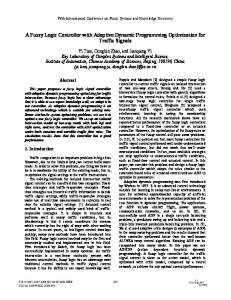
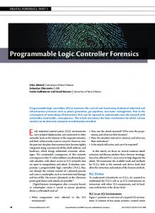
System, Fuzzy Logic Control, Rule based-Variable Structure and Artificial Neural Networks are now considered as viable tools in designing effective and robust drive systems-regulators. Fuzzy logic controllers have been used successfully to control dc motor drives [6, 7, 81. Fuzzy logic controllers are robust and insensitive t o motor parametric changes such as variations in load mechanical time constant and drive operation, hence ensure a robust effective control action under light load, high speed and high firing angle conditions, that usually result in a discontinuous mode of operation and sluggish dynamic speed tracking performance. This paper presents a novel "modified" WCOA defuzzification criterion that results in excellent dynamic tracking response, manifested by good speed reference tracking and minimum motor inrush current for different reference speed trajectories and under light or heavy load conditions, with model parametervariations. The motor inrush currents were reduced significantly during the start-up or acceleration periods of pmdc motor-chopper fed drives using F L controller [6, 7, &?].The F L based controller is also robust enough to deal with any sudden mechanical load excursions and abrupt changes in model parameters and operating conditions. The on-line tuning criteria was needed using the modified WCOA as given in Ref. [7, 8, 91 . The paper presents digital simulation results, fuzzy logic control design, defuzzification-tuning criteria and control system validation under varying reference speed trajectory and loading conditions. Figure (1) depicts the full pmdc-rectifier motor drive scheme. Figure (2) shows the structure of fuzzy logic based controller with the fuzzification, Rule- Assignment table and the "modified" tunable defuzzification stages. Digital simulation for the pmdc motor scheme under different reference speed trajectories and loading
A novel fuzzy logic ( F L ) control scheme to regulate the speed of a permanent magnet (pm) dc motor drive via armature voltage control, has been developed. The pmdc motor drive is fed from a $phase thyristor controlled rectifier. The proposed F L rule based controller scheme utilizes both motor current and speed errors. The firing delay angle (a) of the 3-phase converter is determined as the output of a modijed "weighted centre of area" (WCOA) defuzzifier stage, with an assigned rule base. The controller utilizes novel on-line adjustable defuzzification-weighting criteria to ensure minimum speed overshoot/undershoot as well as reduced motor tmnsient inrush current conditions. The on-lane tuning criteria is based on the speed error excursion level.
1
Introduction
High performance dc motor drives are used extensively in industrial, paper, mining and process industries [I, 2, 3, 4, 51 . The dc motor drive is a highly controllable electrical motor drive suitable for robotic manipulators, position control, guided vehicles, steel and electrical traction [I, 2, 3, 91 . The purpose of any speed regulator is to track a specified reference speed trajectory while rejecting any load or system excursions. Additional control system requirements are also specified such as minimum settling and rise time limits, overshoot/undershoot allowable percentage, limited motor inrush or starting current. Artificial Intelligence ( A I ) technologies are emerging as viable and effective tools in process control parameter, estimation and on-line robust control design, gain adaptation and model state estimation. Expert
0-8186-5320-5/94 $03.000 1994 IEEE
22
conditions were used to validate the proposed fuzzy logic control scheme.
2
(3)
0.0
f i z z y Logic Controller
"'[t
T h e F L controller comprises three stages namely the f u z z i f i e r , rule - base in the fuzzy set and the d e f u z z i f i e r [lo, 11). The motor speed error (e,) is obtained by subtracting the motor speed from its reference speed value, similarly the motor current error ( e i ) is obtained by subtracting the motor current from its reference specified maximum current. The inputs to the fuzzifier stage are the errors e, and ei after scaling and normalization. Fig. (3) depicts the fuzzy sets (f,) for input and output variables defined by the following nonlinear membership function: fa ( C i )
= e2p
-
+
(k8)
=
(Ui)
V, adjustable motor terminal voltage Volt I, armature current A m p J inertia constant N m 2 km back emf or torque constant (in pmdc motor ) "A-' B damping constant N . m / r a d / s e c Ra armature resistance Sl La armature inductance H 2-i load torque ( N . m ) , can be constant, or function of speed as for fan/pump type load.
(1)
V, is the ac supply line-to-line voltage (constant) a t the secondary of interface transformer. The parameters of the dc motor are: 600.0 volt, 1800.0 rpm, 125 HP, R,=0.0874 R,La=6.5 m H , J=2.5, B z 0 . 5 .
* ai (2)
i=N
(4)
w, rotor speed in radls
i=N i=O
oil
Where,
where the of values a and b specify the maximum level of membership grade (MSG)and its width. Tables l and 2 give the constants a and b for the input and output vectors [e,, ei] and Q respectively. The defuzzifier stage is calculated using a new weighted formula as follows [7, 8, 121:
C pk
--
3.1
pk ( g i ) i=O
Dynamic Model of pmdc Motor in Discrete-time Mode
where By using the continuous/discrete "c2d" meta file in the M A T L A B software package the discrete model equations of the dc motor representing the equivalent discrete state was derived using a sampling frequency of 360 Hz.
a (k,) is the firing angle a ( in degree ) at sampling instant (ka), is the sampled value along the entire discourse ai of the polyhedron map , p ( u j ) is the corresponding MSG of the output oil is the number of sampling of the entire N discourse of polyhedron map. is the on-line adjustable "tunable" power of k MSG based on a given adaptation criteria .
3
4
Digital simulation results for the F L control system validation without and with the tunable adaptive defuzzification structure were performed for the following study cases: (1) Motor starting under no - load. (2) Motor starting under no - load then suddenly a p plying full - load. The rule base or assignment table is given in table 3,4. Dynamic simulation were performed for different values of modifier k ( the power of MSG, in the tunable
PMDC Motor Model
The continuous state space model of the pmdc motor drive can be described by the following state space equation:
X
= A*x+B*u
Simulation Results
y = C*x+D*u
23
defuzzifier stage). For study case no. 1, as shown in Fig. (4), when the power k is greater than unity the dynamic speed response overshoot increases and also the settling time increases, but when k is below unity, the overshoot in speed U, decreases, so is the settling time. The overshoot in the speed wm decreases with k reduction until the value (k = 0.5) is reached, but the motor current I,, starts to develop a sustained ripple oscillation with further reduction in k. The defuzzifier output control level also becomes very sensitive to any changes in drive system conditions. So, the advantage of the reduction in speed overshoot, rise time and settling time is offset by this sustained current ripple oscillations. Fig.(5) shows the dynamic response of the pmdc motor for study case no. 2 with different values of modifier (k). It is obvious that decreasing the value of k reduces the speed dynamic overshoot and reduces both the rise and settling times. On the other hand it also increases the steady state error in the speed w m and creates an objectionable sustained current oscillations. So, to overcome this problem an on-line tunable fuzzy logic controller is required. Starting the motor a t specified value k equals unity, t o avoid any starting inrush current, reducing the modifier k value to reduce the speed overshoot. Then, switching back gradually to a value equals unity to cancel any sustained motor current oscillation, and eliminate the steady state error in motor speed, as depicted in Fig. (6). This flexible control system robustness can not be obtained by most conventional control algorithms, such as the P I controllers. So, this novel tunable on-line error driven switching criteria is effective.
Tuning Criteria
4.1
The tuning criteria is implemented as follows:
k=
{
5
Conclusion
unity small Linearlyincrease
The paper presents a novel error driven variable gain fuzzy logic speed controller for pmdc motor drives fed by a six pulse rectifier converters. The tunable F L controller utilizes a modified WCOA in the F L defuzzifier stage to tune the value of member ship grade k on-line based on speed error, to give a better dynamic tracking response, which free from speed overshoot and inrush current. This minimizes the steady state error in speed, while maintaining the motor current below maximum allowable level. The paper presents a simple, novel tuning criteria to implement in the F L controller scheme. Different alternative adaptation criteria can also be utilized to adjust the value of k. Other criteria can be based on speed error, current error and their rates. The dynamic simulation results validated the robustness and effectiveness of the proposed tunable F L controller.
Acknowledgements
NB N M NS IC PS P M P B ' -1.0 -0.66 -0.33 0.0 0.33 0.66 1.0 0.03 0.03 0.02 0.02 0.02 0.03 0.03
a
b
a '
b
R8
R11 R12 R13 R14 R15
86.
76. 1.5
73. 1.5
R9 R10 84. 81. 1.5 1.5 1.5 R18
R19
R20
51.
45.
44.
40.
35.
1.5
1.5
1.5
1.5
1.5
R16 R17
Fig.(l) P M D C motor drive system with F L controller.
if e, > u1 COA if V I < e, > 712 WCOA if e, >= 02 WCOA
69. 1.5
64. 62.0 1.5 1.5
R21 R22 R23 29. 21.5. 18.5 1.5 1.5 1.5
Table 2: The a , 6 constants for output variable firing angle (a)in degree for the rule set
24
Fig. (2) Fuzzy logic controller with tunable change of k in de f u z z i f i e r stage. Fig. (3) The exponential form for fuzzy set. N Negative P Positive
S Small M Medium B Big IC Insignificant Change
Rule assignment table for pmdc motor start under no - lood. caseno. 1. This for second step
Table 3: Rule mignment table for coseno. 1. This for first step
1.1
1
Ref. Speed ( --- ) 1-
?
0.9 -
k=l.O(-)
1,
k = 0.5 ( -.-.-) 0
1
Time 2
(sec)
3
4
Fig. (4) The dynamic response for pmdc motor starting under no - load for unit step in the reference speed and for different values of k, study case no. 1 I
3
I
t
k = 5.0 ( .....)
1.02 1'04
Time (sec)
Time (.sec)
Fig. ( 5 ) The dynamic response for pmdc motor starting under no-load then suddenly applying full- load for different values of k, study case no. 2 25
:!-
k = 1.O
( _._._)
k Tunable (-)
Ref. Speed ( ---)
j/O.*5
k
B I
-
1 .O (
_._I_
0.5.
k Tunable (-
0.9’ 0
I
.
1
Time
)
2 (sec)
) 3
9 I
n-
4
-0
J
1
2
3
4
Fig. (6) The dynamic response €or tunable values of k, study case no.’ 2
s.
0.4‘
0
References
I 1
2
3
U
4
Time (sec)
Table 4: Rule assignment table for case no. 2.
[l] P.C. Sen, ”Thyristor DC Drives,” John- Wtley & Sons, New York, 1981.
[7] Hussein F. Soliman, A.M. Sharaf, M.M. Mansour, S.A. Kandil and M.M. El-Shafii, ”Robust Variable Structure Fuzzy Logic Speed Regulator for PMDC Motors,” MEPCON’94, Giza, Egpypt January 3-6, 1994 accepted paper.
[2] Y.Y.Hsu and W.C. Chan, ”Optimal Variable Structure Controller for DC Motor Speed Control,” IEE P m . , Vol. 131, Pt.D, No. 6, pp. 233237, November 1984.
[8] Hussein F. Soliman, A.M. Sharaf, M.M. Mansour, S.A. Kandil and M.M. El-Shafii, ”Tunable Fuzzy Logic Controller for a Chopper fed DC Motors,” MELECON’94, 7’th Medit. Electr. Conf., Antalya, Turkey, April 12-14, 1994 accepted paper.
[3] J.Zhang and T.H Barton, ”Robustness Enhancement of DC Drives with a Smooth Optimal Sliding Mode Control”, IEEE Trans. on Ind. Appl., Vo1.27, No.4, pp. 686-693, July/August 1991. [4] B.A. White, R.T. Lipczynski and A.R. Daniels, ” A Simple Digital Control Scheme for DC Motor,” IEE Proc. B, Electrc. Power Appl., 130, (2), pp. 143-147, 1983.
[9] A.M. Sharaf, A. Ghosh, ”Speed and Torque Regulation of Permanent Magnet DC Motors Using Rule Based Fuzzy Logic Control,” Proceeding IEEE, Intelligent Vehicle Symposium, Tokoy, Japan, July 14-16, 1993.
[5] B. Phutal, ”Novel Closed Loop Control Scheme for Thyristor-fed DC Motor,” J . 1nst.Eng. (India) Electr. Eng. Diu., pp. 333-338, 1978.
[lo] L.A. Zadeh, ”Fuzzy Sets,” Information & Control, Vol. 8, pp.338-353, 1965.
[6] Hussein F. Soliman, A.M. Sharaf, S.A. Kandil, M.M. Mansour and M.M. El-Shafii, ”A Hybrid Fuzzy Logic Speed/Current Controller For A DC Motor Chopper Drive System,” AEIC’ 93, Cairo, Egypt, Dec. 18-21 1993 accepted paper.
[ll] Earl Cox, ”Fuzzy Fundamentals,” IEEE Spectrum, Oct. 1992.
[12] Z.G.Chen, S.J. Cheng and H.J. Hu, ”A Fuzzy Power System Stabilizer,” proceeding of IPEC-93, pp 410-415, Singapore, 1993.
26