Recoding of binary numbers has been used in computer arith- metic with 3-bit .... where digits Di are one of { -2, - 1 , 0, +l, +2} found from by looking up the Y ...
1006
!PEE TRANSACTIONS ON COMPUTERS, VOL. 39, NO. 8, AUGUST 1990
A Generalized Multibit Recoding of Two’s Complement Binary Numbers and Its Proof with Application in Multiplier Implementations Abstmct-A multibit recoding algorithm for signed two’s complement binary numbers is presented and proved. In general, a k +I-bit recoding will result in a signed-digit (SD) representation of the binary number in radix 2 , using digits --p-’ to +p-’ including 0. It is shown that by scanning k + l-tuples (k 2 1) with one bit overlapping between adjacent groups, a correct SD representation of the original number is obtained. Recoding of binary numbers has been used in computer arithmetic with 3-bit recoding being the dominant scheme. With the emergence of very high speed adders, hardware parallel multipliers using multibit recoding with k > 2 (i.e., more-than-3-bit recoding) are feasible with potentials of improving both the performance and the hardware requirements. A parallel hardware multiplier based on the specific case of 5-bit recoding is proposed. Such an implementation would use three fast adders to produce the odd multiples of the multiplicand while reducing the size of the carry-save-adder array by 50% compared to the classic case of 3-bit recoding. Extensions beyond 5-bit recoding for multiplier design are studied for their performance and hardware requirements. Other issues relating to multiplier design such as multiplication by a fixed or controlled coefficient are also discussed in the light of multibit recoding.
TABLE I MODIFIED BOOTH’S RECODING
001 010 011 100 101 110 111
+lY +1Y +2Y -2Y -lY -lY -0Y
ECODING of binary numbers was first hinted at by Booth 11 close to four decades ago while he was considering the problem of multiplying two signed binary numbers in digital computers. His algorithm treated positive and negative numbers in two’s complement format indiscriminately and therefore proved to be an attractive solution. In essence, the Booth’s algorithm looks at 2 bits of the multiplier number X and depending on the particular combination at hand it does one of the three operations. If x;x;+l = 00 or x;x;+l = 11 then shift the existing sum of partial products one bit to the right. If x;x;+l = 01 then add the multiplicand Y to the existing sum of partial products and then shift the result one bit to the right.
If X;X;+~ = 10 then subtract the multiplicand Y from existing sum of partial products and then shift the result one bit to the right. The process starts by appending a 0 to the right of the LSB of the multiplier X (denoted by x-1) and then looking at binary pairs beginning with x-1.’ Adjacent pairs share one bit so that in every iteration only one bit of the multiplier retires. It is worth noting here that the required multiples of the multiplicand are Y and - Y which are readily available if adders and subtracters are employed. n iterations are required for a multiplier X with word size n. A decade after Booth’s paper, MacSorley [2] proposed a modification to Booth’s algorithm in which a triplet of bits instead of a pair was looked at in every iteration.* His scheme is summarized in Table I. The Modified Booth’s Algorithm also starts by appending a 0 to the right of XO. Here triplets are taken again beginning at position x-1 and continuing to the MSB with one bit overlapping between adjacent triplets. If the number of bits in X (excluding x-I) is odd, the sign (MSB) is extended one position to ensure that the last triplet contains 3 bits. At every step, a multiple of multiplicand Y is added to the partial product according to Table I and the result shifted right by 2 bits. If n represents the (even) number of bits in the multiplier X after any sign-extension is performed, then a total of n / 2 iterations would be required in a multiplication X x Y , two bits of X retiring and two product bits resulting from every step.
Manuscript received August 22, 1989; revised March 2, 1990. The authors are with AT&T Bell Laboratories, Allentown, PA 18103. IEEE Log Number 9036136.
This and all the following recoding algorithms can start at either end of X . In this paper, we start the recoding always from x - I . A proof of the Modified Booth Algorithm was later given by Rubinfield [31.
Index Term-Booth’s Algorithm, computer arithmetic, fixed coefficient multiplier, multibit recoding, multiplier recoding, overlapped scanning, parallel multiplier, signed-digit arithmetic.
I. BACKGROUND
R.
+
0018-9340/90/08OO-1006$01.OO O 1990 IEEE
1007
SAM AND GUPTA: RECODING OF TWO'S COMPLEMENTBINARY NUMBERS
questions by developing a multibit recoding algorithm which is based on signed-digit number systems.
TABLE I1 EXAMPLES OF SD-REPRESENTATION IN RADIX 4
AND MULTIBIT RECODING 11. SD REPRESENTATION
A signed-digit number system [4] in radix r is based on a redundant set of signed digits
111011 000000
000
+12
001100
iio
+23
0101 1 1
i z i
{-a, -(a
-
l), . . . , -1,o, 1,. ' . ,a
where
The advantage of the Modified Booth's Algorithm (MBA) over Booth's original algorithm lies in the reduced number of iterations required, the reduction being from n steps to n/2 steps for MBA. This improves both speed and hardware requirements (in the case of a hardware parallel multiplier) when doing a multiply operation. This gain is possible at the expense of somewhat more complex operations at every step. It should be noted, however, that the required multiples of Y (0, fY , f2Y) are available by merely shifting Y to the left, provided subtraction as well as addition can be done at every step. Although the algorithms and operations specified above seem rather arbitrary at the first sight, they are both based on meaningful number systems. If one focuses on what in effect is being done to X in the two schemes and ignores the multiplicand Y and the multiplication process altogether, then one may arrive at a different representation for the two's complement number X . In the case of MBA, then, we may arrive at the following representation for X :
a
=
I;]
CDi.4'
(2.1.0)
+
+
A . Multibit Recoding Algorithm Let X be an n-bit two's complement format binary integer. The value of X can then be found from:3 n -2
.2"-l
+ pq .24.
n/2-I
=
1, a }
is chosen for minimum redundancy. Note that the total number of digits available (2a 1) does imply a redundant number system in radix r (because r 5 2 a 1). For example, if r = 8 then a = 4 and a redundant set of 9 signed digits ( 0 , f 1, f2, f 3, f4) is used to represent numbers in this system. Schemes of conversion from decimal numbers to a given SD representation exist (see [4] for example) but are usually not amenable to machine implementation due to their complexity. We will show that if we start from a binary 2C number then the SD representation in radix 2k can be obtained through what may be called a generalization of Booth's recoding algorithm.
x = -xn-l X
-
(2.1.1)
a =O
('*')
i =O
where digits Di are one of { -2, - 1,0, + l , +2} found from Tablq I based On the Of trip1ets Of form t X i + 2 9 xi+l x i > by looking up the Y coefficients in that table. Here we have a signed-digit (SD) representation of X in radix 4 (note that the radix 4 representation corresponds to 2-bit shifts of partial product in the MBA multiplication). Some examples may help to illuminate the concept. Applying the MBA scheme mentioned before to the multipliers -29, -5, 0, +12, and $23 results in the radix 4 numbers shown in Table 11. The negative sign of the digit is usually shown as a bar above the digit to aid the clarity of representation. The two's complement (2C) format is assumed to be 6 bits wide in these examples. The first signed digit of - 29 was found by appending a 0 to the right of LSB. Then the first triplet (1 10) was looked up in Table I to correspond to - 1. Other digits are found similarly by looking up digits corresponding to triplet values (sharing one bit from the previous triplet) from Table I. But how are the entries in Table I obtained? Can these results be extended to other radices? And if so, what ensures that algebraic equivalence is preserved? Unfortunately the available literature seldom refers to the number systems underlying recoding and therefore makes such questions difficult to answer. The following section attempts to answer such 9
Note that this is a uniform representation for both positive and negative numbers. X is positive if xn-l = 0 and is negative if X,-l = 1. An SD representation of X in radix 2k ( k 2 1) will have n / k signed digits4 Dn/k-l, Dn/kP2,.. . ,D1, Do. In this new radix (2k) the value of can be rewritten as
x
n/k-I
X =
Di .2ki
(2.1.2)
i =O
where digits Di are found from bits xi of X according to
(2.1.3) Binary integers are chosen to work with in this paper because their treatment is easier to follow than binary fractions which require negative powers in their representation. Obviously, the results derived are independent of the format used to represent the numbers and are equally valid for any binary 2C number. An n-bit 2C fraction can be conveniently converted to an n-bit integer by multiplying it by 2"-'. It is easily shown that sign-extension in 2C numbers does not change the value of the number. Therefore, if the number of bits in X is not divisible by k then the sign of X can be extended as many positions as required (at most k - 1) to make the new number of bits divisible by k. In this paper, n represents the number of bits in X after any sign extensions are performed and hence is always divisible by k .
1008
IEEE TRANSACTIONS ON COMPUTERS, VOL. 39, NO. 8, AUGUST 1990
B . A Proof of the Multibit Recoding Algorithm
and
x-1
=o
(2.1.4)
by definition which represents the appended 0 bit to the right of xo. Note that (2.1.3)simply evaluates the inner product
We want to show that digits Di as specified in (2.1.3)above correctly represent X in radix 2k. Note that based on these signed digits, the value of X is represented as in relation (2.1.2). The proof consists of substituting the value of Di from (2.1.3) into (2.1.2) and showing that the result is the same as the two's complement binary value of X as given by (2.1.1). After substituting the value of Di from (2.1.3)into (2.1.2) and rearranging we obtain nlk-1
nlk-1 k-1
(2.1.5) The first summation can be expanded and rearranged as follows: If we let X i and K represent the two vectors above then (2.1.3) x-12' -Xk-12k-' +Xk-12k -X2k-]22k-' +X2k-122k - " ' can be rewritten in short as
Di = X i . K .
(2.1.6)
- xn--k-12n--k--l +xn--k-12n--k -x,42n--1
+
= x-120 +x/+12k-' +x2/+12*k-' .' The two vectors in (2.1.5) above each have k 1 elements +xn4+12fl-k-1 -x,-12"-1. and therefore a k 1-bit recoding process corresponds to performing n / k such inner products. Some explanation of various elements in (2.1.3) may help one better see this correspon- Using the fact that x-1 = 0 to replace 2O with 2-' for the dence. The subscripts of x of the form k . i plus an index refer coefficient of x-1 and bringing the negative term first, the to the fact that k new bits of X (plus an overlapped bit) are above value for the first summation of (2.2.1)can be rewritten considered at a time for each signed digit D i . For each digit as Di the subscripts of x range from k . i - 1 to k(i 1 ) - 1 covering the same k 1 bits of X as specified in the first vector nlk-1 in (2.1.5). This digit calculation needs to be repeated n / k times so that (2.1.2)fully evaluates X . One can also easily see l. indicates the that digits Di and Di+l share bit ~ k ( i + ~ ) - This overlapping bit between adjacent k 1-tuples. Note, however, Substituting this value for the first summation into (2.2.1)we that the coefficient of this bit is - 2k-1 when calculating Di obtain while a coefficient of 1 is used for this bit when calculating n fk-1 Di+l. The minimum value of Di is found by letting X i be = -x,-12"-' + Xkj-12ki-' equal to [ l 0 . . .01 which yields - 2k-' and the maximum i=O is 2k-1 obtained by letting Xi be equal to [0 1 . . . 1 ] . All the nlk-1 k-1 integer values in this range can be assumed by digits Di when X i assumes all its possible binary values. Finally note that the second vector in (2.1.5) is a constant vector which is fixed for a given k (i.e., for a given radix 2k). The whole process nlk-1 k-1 --x,-I~~-' c x k i + j - 1 2 ki+j-1 . (2.2.2) of calculating the new digits from the binary numbers using the inner product (2.1.6) can therefore be thought of as a i=O j = O discrete convolution between the input data sequence X and the fixed response vector K. The only difference is that in a Expansion can easily show that, for constant integers k, q, real convolution the input data are shifted only once when a and t , the following relationship always holds true: new output is to be calculated whereas here it is shifted k Q k-1 kq+k-1 +t times between two output digits. xxxki+j+t xu. (2.2.3) The above results on multibit recoding are summarized in i=O j = O U =t Section 11-C. The next section proves that the above equations lead to a valid representation of X in radix 2k. It can be Equation (2.2.3) above reflects two different ways of finding skipped if desired without any loss to the continuity of the the sum of elements in an array with k(q 1 ) elements. On the material presented. left, we put the elements of the array into a two-dimensional
+
+
+
+
+
x
+
+
1009
SAM AND GUPTA: RECODING OF TWO'S COMPLEMENT BINARY NUMBERS
array with q + 1 rows and k columns and use the double summation to add the sums of individual row elements together. On the other hand, the right side shows the sum of all elements as ordinarily found from a one-dimensional array. In order to use (2.2.3) above to unfold the double sum in (2.2.2) into a single sum, we should replace t with - 1 and q with n / k - 1. Therefore, the new limits of the summation will go from - 1 to k ( n / k - 1) k - 1 - 1 which is equal to n - 2. Now x-1 is equal to 0 by definition and therefore (2.2.2) results in
+
n -2
X
=
-xn-12"-'
+c x u 2 u . U
(2.2.4)
=o
The proof is therefore ~ o m p l e t e .The ~ above value of X is identical to the one in (2.1.1) for an n-bit two's complement binary number X and therefore shows that recoding does not alter the algebraic value of the binary number. It also proves that any two's complement number can be represented in any radix 2k (k 2 1) by signed digits Di as given by (2.1.3). Finally note that x-1 = 0 is merely a convention required for relation (2.1.3) to calculate the value of DOcorrectly. If DO is treated separately by letting X O contain k bits instead of k 1 bits, thus dropping x-1, then this convention may be dropped.
+
C . Summary of Multibit Recoding The multibit recoding algorithm can be summarized as follows. An SD representation of a 2C binary number X in a given base 2k is obtained using the following steps. 1) Extend the sign bit of X by as many positions as necessary (at most k - 1 positions) so that the total number of bits n is divisible by k. 2) Append a 0 to the right of the LSB of X and denote this bit by x - ~ . 3) Form vectors of k + 1 bits starting from x-1 (see footnote 1) such that adjacent vectors share one bit. For example, the MSB of vector X Ois the same as the LSB of vector X I . 4) The inner product of each vector X ; with the constant vector '2l
2O
11
yields a signed digit Di . Alternatively, relation (2.1.3) can be used to calculate Di . 5) Digits Do through Dn,k-l obtained above represent X in base 2k. Each digit may assume values in the range - 2k-' to 2k-' including 0. To ease the digit computations, one can form tables showing the digits corresponding to all possible k + 1-tuples for a given k . Given are Tables 111-VI for k = 1, k = 2, k = 3, and k = 4 corresponding to radices 2, 4, 8, and 16, respectively. Note that the Modified Booth Algorithm of Table I corresponds to the multibit recoding with k = 2 as shown in Table IV. The authors recently learned of another proof for the general recoding case [5]. In that proof, the authors do not take advantage of the signed-digit number system underlying the recoding process and restrict their treatment to multiplier implementations. The ensuing proof is therefore quite complicated compared to the one given here. See [5] for more information.
TABLE I11 2-BIT RECODING (k
I
Pair Value
1)
=
Signed Digit Value
0
TABLE IV 3-BIT RECODING (k = 2) Triplet Value
o00 001 010 01 1 100 101 110 111
4-BIT
-2 -1 -1 0
TABLE V ( k = 3)
RECODING
Quadruplet Value
oooo o001 0010
Signed Digit Value 0 +1 +1 +2
Signed Digit Value 0 +I +I
001 1 0100 0101 0110 0111 lo00
+2 +2
IOOl
-3 -3
1010 1011 1 100 1101 1110 1111
+3 +3 +4 -4
-2 -2 -1 -1
0
Also, the original Booth recoding technique (see Section I) corresponds to the case of k = 1 as shown in Table 111. These tables can be implemented in hardware, as is the case with parallel multipliers and SD adders, or in softwarehrmware, as is the case with software multiply instructions. Recoding of binary numbers has been used to implement various arithmetic blocks such as multipliers, dividers, and signed-digit adders (see [4]). In the remainder of this paper, however, we limit our treatment to applications of recoding to hardware parallel multipliers.
III. APPLICATIONS OF RECODING IN MULTIPLIERS Various classes of multipliers such as serial multipliers, parallel multipliers, and the microprogrammed or software multipliers have all used the Modified Booth Algorithm to reduce the multiplication time. We will focus on the applications of recoding to hardware parallel multipliers and will show how multibit recoding may affect the design and performance of this class of multipliers. Afterwards, some special cases are covered for which multibit recoding may prove particularly advantageous.
1010
IEEE TRANSACTIONS ON COMPUTERS, VOL. 39, NO. 8, AUGUST 1990
TABLE VI 5-BIT %CODING (k = 4) Puintuplet Value 00000
Signed Digit Value 0
oo001 m10 m 11 00100 00101 00110 00111 01m 01001 01010 01011 01100 01101 01110 01111 loo00 loo01 10010 10011 10100 10101 10110 10111 1 loo0 11001 11010 11011 11100 11 101 11110 11111
+1
+1 +2 +2
+3 +3 +4 +4 +5 +5 +6 +6 +l +7
+8 -8 -1 -1 -6 -6 -5 -5 -4 -4 -3
-3 -2 -2 -1 -1 0
As mentioned in Section I, hardware multipliers have used recoding of the multiplier number ever since the idea was first proposed. The dominant scheme has been the Modified Booth Algorithm (MBA) used along with the so-called carry-save adder (CSA) array to implement a parallel multiplier. This results in a very regular layout for the multiplier as well as high speed of multiplication. 3-bit recoding of the multiplier number (X in the X x Y operation) in effect results in multiplication in the higher radix 4 and achieves a more parallel operation. This is achieved by multiplying the multiplicand Y by signed digits 0, f 1 , and f2 instead of by binary digits 0 and 1 at each step of operation. It is intuitively obvious that in a higher radix, for example using a 5-bit recoding, fewer operations would be required to finish the multiplication provided multiplication by the higher digits can be easily accommodated. This requires very high speed carry-propagate adders to generate odd-digit multiples of the multiplicand Y . To this end, a high-speed carry-propagate (CP) adder has been designed which makes it possible to generate the odd multiples of Y in a time comparable to the recoding time of X. The adder is of the carry-select type [6] and is designed to optimize the carry-propagate and carry-select paths for higher speed, thus achieving the performance required for higherradix recoding. Here we will first review the architecture of a conventional multiplier using MBA. Then a multiplier architecture is proposed which uses 5-bit recoding of X along with the optimized carry-select adders for the generation of odd multiples. Various considerations for multipliers based on multibit recoding technique are addressed in the end.
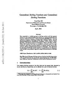
A . 3 -Bit Re;coded Multiplier [4], p] Fig. 1 shows the architecture of a typical parallel multiplier using MBA. The multiplier X is n bits wide and the multiplicand Y has m bits. There are n / 2 3-bit Booth encoders each taking 3 bits of the X and generating control lines to select one of the multiples of the Y (0, fY , f2Y) to be applied to the inputs of one row of the carry-save adder (CSA) array. Each encoder implements the truth table of Table IV which corresponds to radix 4 representation (k = 2) for X. Each row of the CSA array consists of m + 1 selectors each feeding an adder (no adders for the first row, half adders for the second row, and full adders for the rest). Each row of the selectors therefore selects one of the different multiples of Y and applies it as one input to the adder row. It should be emphasized again that the only multiple of Y requiring special treatment is 2Y which can be easily obtained by shifting Y one position to the left (by hardwired displacement of Y one bit to the left in hardware). Negative multiples are obtained by complementing the multiple and then adding a 1 in the final twin adder. The sums and carries of each row of the array reflect the partial product accumulated up to that point and in turn are applied to the next row to be added to a new multiple of Y . Each row also produces 2 bits of the product in the same way that a long-hand multiplication produces one digit of the product each time two consecutive results are added. After the first n bits of the product are produced on the right through the twin adders (i.e., adders with 2-bit carry look-ahead (CLA) which propagate the carry from one row to the next), m bits of carry propagation is required to produce the final m bits of the product. This can be done through any m-bit carry propagate (CP) adder and twin adders are used here to generate these product bits faster. The most important attribute of a parallel multiplier is its speed performance. This is usually the driving force for a parallel multiplier. Next is its silicon area and dimensions. For the above multiplier, the multiplication time can be divided into the following components: The Booth encoder delay. With the current 0.9 pm CMOS technology a delay of 3 ns is typical. Note that the encoders are used in parallel and therefore their delays do not accumulate. The delay of the CSA array or of the n / 2 twin adders producing lower product bits, whichever is larger. Usually, the twin adders are designed to outperform the adder array for optimum performance. This delay is then equal to ( n / 2 1) x (one carry-save adder delay). A delay of about 1.80-2.0 ns is obtained with the current technology for a carry-save adder. The delay of the final carry propagation6 which is equal to m / 2 x (one twin adder delay). The twin adder’s carry path delay is about 2 ns for the current technology. The area of a multiplier can be roughly measured by looking at the number of rows and columns that make up the multiplier A more accurate estimate for the carry propagation should account for the setup time of the first stage of the CLA circuit. This delay increases as the size of CLA is increased.
1011
SAM AND GUFTA: RECODING OF TWO’S COMPLEMENT BINARY NUMBERS
P[n:n+m-I] Fig. 1 .
Parallel multiplier with 3-bit recoding.
J C q - S a h C l Adders
Selecbr and
X(n-1:O)
5-m Bmlh
MulIipIier
Cany-Saw AUer +,
Enc.
Amy (m+3 Columns)
(d4 Rows)
Bits
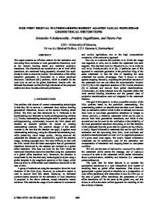
Fig. 2 . Architecture of multiplier with 5-bit recoding.
as well as the relative complexity of each cell making up the rows or columns. In this case, we are dealing with n / 2 rows by rn 1 columns. The elements making up each row are one 3-bit Booth encoder, rn 1 selectors (1 of 5) and adders, and one twin adder. A recent 16 x 16 multiplier using 3-bit recoding in 0.9 pm CMOS has a delay of 25 ns and an area of 0.73 mm2. Other examples of 3-bit recoded multiplier design as well as the design issues involved can be found from the reference list [8], [9].
+
+
B . Proposal for a 5-Bit Recoded Multiplier Maybe the most formidable obstacle in going to higher bit recoding schemes has been the generation of odd multiples of the multiplicand. Such multiples can be formed by addition or subtraction of two (or possibly more) power-of-2 multiples
of Y . Such a scheme would have an acceptable performance if the adder delay can be justified in relation to the overall performance gain of the multiplier. Since the generation of the multiples of Y takes place in parallel with the recoding of the multiplier X , it is highly desirable to have an rn-bit adder delay comparable to the delay of the recoder. The optimized carryselect adder mentioned before achieves such a performance goal. Given in Fig. 2 is a block diagram of the 5-bit recoding parallel multiplier. The salient features of this multiplier which set it apart from the previous one are as follows. 1) The multiplier is now recoded in 5-bit groups. This corresponds to radix 16 representation (k = 4) for X using signed digits 0, f 1, . . . , f 8. Each recoder cell is larger (five inputs and ten outputs) than before but only n / 4 of these
1012
IEEE TRANSACTIONS ON COMPUTERS,VOL. 39, NO. 8, AUGUST 1990
TABLE VI11 REPRESENTATIVE DELAYS FOR MU BIT RECODED MULTIPLIERS
TABLE VI1 FOR PROPOSED MULTIPLIER ADDERS NEEDED Multiple
Operatio0
Adder Size
Multiplier Size
m+2 m+3
RecoderDelay
8Y - Y
36x36
48x48
64x64
4ns
411s
4ns
4ns
4ns
14ns
22ns
34ns
46ns
62ns
16ns
24ns
3211s
42ns
42ns
62ns
82ns
108ns
Final Carry llns . ~ P a L W ~ ~ Y Total Delay
29ns
TABLE IX REPRESENTATIVE DELAYS FOR BIT RECODED MULTIPLIERS WITH CARRY-SELECT USEDFOR THE FINALSTAGE 16x16
Multiplier Size ~
24x24
,
I
8ns 8ns Ens
36x36
9.5ns t llns
8ns ~
~
Final Cany Select Select Delay Delay Total Delay
+
+
24x24
1 I I I I I
CSA Array
are required as compared to n/2 for MBA. The ten outputs of the recoder select one of the 17 different multiples of Y (0, & Y , f 2 Y , f 3 Y , f 4 Y , f 5 Y , f 6 Y , &7Y, f 8 Y ) . The ten select lines can be mnemonically referred to as Sign, Zero, One, Two, Three, Four, Five, Six, Seven, and Eight. The Boolean equations to implement these signals are easily obtained from Table VI and have some minterms in common. 2) The carry-select adder block is a new block which does not exist in the 3-bit recoded multiplier. It consists of three adders which are used to obtain the odd multiples of Y according to Table VII. 6 Y is obtained by displacing 3Y one position to the left. All the other multiples (Y, 2Y, 4Y, and 8Y) are available by shifting Y (i.e., hardwired displacement) to the left by 0, 1, 2, or 3 bits, respectively. 3) The CSA array now has only n/4 rows instead of n/2. Each row consists of m 3 selectors selecting one of the nine multiples (0 Y through 8 Y) with the Sign selecting addition or subtraction. Again the first row has no adders, the second row has half adders, and the rest are full adders. Therefore, the delay Of CSA array is approximately equal to (n/4- 1) (one carry-save adder delay). 4) Each row of the array generates four product bits instead of two. This requires the use of fast carry-propagate adders to generate the 4 product bits and the carry input to the next stage in the same time interval that a carry-save adder row is updating the partial product. The use of quad adders with 4-bit carry look-ahead (CLA) achieves the under 2 ns carry delay required here. 5) The final m bits of the product are generated by an rn-bit carry-select adder. This can be done due to the timing nature of the inputs to the final carry-propagate stage which makes all the inputs available by the time the first input (bottom righthand side) is ready. Another speedup, therefore, is achieved here through the carry-select adder with representative delays of 8 ns for 16 bits, 9.5 ns for 24 bits, and 10.5 ns for 32 bits. The above features of the new multiplier make it an attractive choice because of its higher speed performance and at the same time good area cost while keeping the regular layout structure. The higher speed is achieved by reducing the array delay by more than half which can be specially significant for very large multiplier sizes (say 48 x 48). The array delay reduction is gained at the expense of a few nanoseconds of penalty, i.e., the difference between the m 3-bit carry-select delay (for generating 7Y) and the recoder delay. The use of carry-select adders for the final propagation of carry improves the performance even further. As far as the area is concerned, great improvements are obtained by reducing the size of the amay by half while paying the price of somewhat bigger selectors and recoders as well as the three additional adder blocks. Whether or not area is increased significantly is to a good degree a function of the layout tech-
16x16
48x48 ~12.5ns
64x64
14ns
y
II 1I 1I 1I 1 ,
9.511s 9.511s
llns llns
12.5ns 12.5ns
14ns 14ns
29ns
37ns
47ns
58ns
TABLE X VARIOUS FEATURES OF MULTIPLIERS USINGMULTIBIT RECODING Recoding
No. of
6 Bits 7 Bits
17 33 65
&lector
1 4 4 1-of-8 1~f-16 l-of-32
No. of
Normsllked
7+2 15+8
0.66 0.50 0.40 0.33
CLA
4 6
niques used to implement the multiplier and of the size of the multiplier itself (i.e., values of m and n). It is believed that superior performance is possible at the expense of at worst a little area penalty using this scheme with both area and performance enhancing further as the word size of multiplier and multiplicand (n and m)are increased. This is in contrast to the Wallace tree [ 101 implementations which have highly irregular layouts while their area penalty for speed improvement is rather severe. Tables VI11 and IX show some of the expected delays for 5-bit scheme compared to the 3-bit (MBA) scheme. All of the above delays are based on ADVICE [111 simulations of the individual cells under the worst case slow process files at 125°C and 4.2 V supply. Note that in Table IX the recoder delay is replaced by the delay of the carry-select adder generating the odd multiples of Y because this delay is larger than the recoding delay. As is evident from the above delay figures, the future generations of multipliers can particularly benefit from the proposed architecture and the speed gain it offers.
c. Multiplying by a Fixed or Controlled Coeficient It is worthwhile noting here that in specialized DSP applications, where a multiplier can be dedicated to multiplying input data by a fixed coefficient, considerable savings in area
1013
SAM AND GUPTA: RECODING OF TWO'S COMPLEMENT BINARY NUMBERS
bits of the product fall off from each row of the CSA array. This requires high-speed k-bit adders to produce k bits of the product and the carry into the next stage in the same time that one row of the CSA array produces the outputs into the next row. This was the reason for using quad adders (i.e., 4-bit CLA adders) in the proposed architecture and currently this should be done in under 2 ns. Obviously the task becomes more formidable as the number of carry-propagations to be done in this time period is increased. The setup time needed for a larger size CLA adder is also increased making the design goal further difficult to achieve. The size of carrylook-ahead circuit needed for various recoding sizes is shown in the last column of Table X. The main advantage of going to a higher bit encoding lies in its reducing the CSA array delay. Since the delay of the CSA array is only halved by doubling the size of k and since the addition of each bit to recoding size requires about twice as many digits to generate and choose from, then the point of diminishing returns is reached very quickly considering the exponential growth of hardware elements and the obstacles mentioned above. We believe that 5 bits ( k = 4) is the optimum recoding size given that the delay of CSA array is halved compared to the 3-bit case by requiring only three extra additions to be performed. The 1-of-8 selectors needed also seem to be manageable specially from a layout standpoint where the selectors can feed the adders without compromising the compactness of the layout. The height of the selector D.Considerations for Higher Bit Recoding cell will increase in the same direction as the reduction of the Every time the recoding size is increased by one bit, the rows of the CSA array and thus the overall aspect ratio of the number of digits required to represent the binary number is multiplier is not considerably changed. Finally the 4-bit CLA doubled (not counting 0). This means that a multiplier to be circuit needed is manageable from a design and area standimplemented with a recoding size of one bit more will require point as experiments by authors have shown to be the case. selectors which should select from twice as many digits as be- As a final indication of the optimality of the 5-bit recoding, fore. Also the number of odd multiples of the multiplicand is a comparison to the 9-bit recoding is given. The use of 9almost doubled requiring more carry-select adders to imple- bit recoding would offer only a modest 25% improvement in ment those multiples. On the other hand, with recoding sizes the array delay over the 5-bit case while requiring 1-of-128 of more than 5 bits, there are some multiples of Y (such as selectors and the generation of 63 odd multiples of Y! An estimating formula is presented below which provides 11Y) which can only be obtained by addition of more than two power-of-2 multiples (in this case SY, 2Y, and Y). Such the delay figure for a parallel multiplier implemented via a multiples can be formed by using carry-save adders to reduce CSA array and using k 1-bit recoding of the multiplier X . the summands (i.e., power of two multiples to be added) to It is assumed that X and Y are, respectively, n bits and m two numbers and then by a carry-select adder to obtain the bits wide. It is further assumed that the k-bit carry-look-ahead required multiple. However, the operations required and the delay is less than or equal to the delay of one stage of the CSA number and complexity of circuits needed to implement them array. very quickly prohibit a practical multiplier design using higher Tk+l(n x m ) = max[((k + 1)-bit recoder delay), bit recoding schemes. Given in Table X are some of the hardware requirements for various multipliers using k + 1-bit re((m k - 1)-bit CP adder delay (y - 1) coding. For recoding sizes of more than 5 bits, the two difx (one CSA stage delay))] ferent types of adders required are shown as the sum of two numbers under the Extra Adders column. The first number is 1 x (one CSA stage delay) the number of carry-select adders and the second one of the number of carry-save adders. More than two additions may (m-bit CP adder delay). (3.4.1) become necessary for higher bit recodings. Another design difficulty in going to-higher bit recoding In (3.4.1) above, the first term represents the maximum of the comes from the fact that in a k + l-bit n ~ o d e dmultiplier, k two delays associated with parallel operations of recoding and odd-digit multiple generation. In generating odd multiples, at 'An example would be when the multiplier coefficients are stored in a ROM. In this case, the approximation can be done before storing the values most 7 additions (Of + shifted Of be so that no extra operations take place before multiplication. performed where y is a heuristic number associated with the
can be achieved which reduce the area below the equivalent 3-bit implementation. This is because, assuming that the fixed coefficient is applied to the multiplier X , recoders and selectors will no longer be necessary and direct hardwiring of various multiples of Y to various rows of the array will serve the purpose. Another interesting speed and area enhancement in this case may be possible by approximating the fixed coefficient by another coefficient which uses only quintuplets corresponding to powers of 2 (see Table VI). If such an approximation is possible and acceptable then the three carry-select adders for generating odd multiples of Y can also be removed thereby improving both the area and speed even further. It seems that one should be able to find analytic transformations to approximate any binary 2C number by another one which can be represented by power-of-2 signed digits in a given radix 2k (in this case in radix 16). If such a transformation exists and can be applied satisfactorily to the multiplier numbers7 X or if the algorithms using multiplication can be modified to use only coefficients with power-of-2 signed digits, then a more general multiplier may also do away with the three carry-select adders and their associated delay. In this case, the selectors and the recoding logic are also simplified. Such special purpose multipliers should be studied as potential options for dedicated applications where the higher speed and the smaller area offered are very desirable.
+
+
+(&- ) +
+
1014
IEEE TRANSACTIONS ON COMPUTERS, VOL. 39, NO. 8, AUGUST 1990
TABLE XI WORST CASENUMBER OF ADDITIONS ( 7 ) TO GENERATE ODD FOR DIFFERENT RECODINGSIZES MULTIPLES RPcodingSize
2
3
4
5
6
7
8
9
0
0
1
1
2
2
3
3
*+U Y
“worst case” multiples of Y for the given recoding size of 1. The first y values would be reduced through y - 1 CSA stages. The final carry propagation to generate the odd multiple would be performed by a CP adder, such as a carryselect adder, which would be at most m k - 1 bits wide (corresponding to the multiple [2k-’ - 11Y). The values of y for recoding sizes of up to 9 are given in Table XI. As may be seen, a relation of the form y = [(k- 1)/2J is strongly suggested by the table. The second term in the delay equation (3.4.1) corresponds to the CSA array delay which is approximately in inverse proportion to k - 1. Finally, the last term in the delay formula corresponds to the last m-bit carry propagation which generates the most significant bits of the product. It is worth mentioning here that a 4-bit recoding scheme (corresponding to Table V with k = 3) is quite feasible and straightforward to implement by requiring only one carryselect adder to produce the term 3 Y and 3-bit CLA adders to propagate the carry. The selector size of 1-of-4 is also rather convenient to design and work with. The improvement in the delay of the array (33%), however, is not as large as the 5bit case. Nevertheless, it is a good choice for some moderate improvement in the speed of multiplication. It is interesting to note that MacSorley (see [2]) mentioned the case of 4-bit recoding at the same time as the Modified Booth Algorithm. However, it was not as widely adopted due to the difficulty in generating the term 3Y. Again attention should be paid to special purpose multipliers which multiply by fixed or controlled coefficients and the improved area and performance which may result from this (see Section 111-C). It should be noted, however, that an increase in the recoding size implies coarser approximations if only power-of-2 signed digits are available. If the resulting approximations are satisfactory, then such multipliers may offer superior area and performance using higher bit recoding schemes.
k
+
+
IV . CONCLUSION A generalized recoding scheme for signed two’s complement binary numbers is presented. It is shown that multibit recoding of two’s complement binary numbers corresponds to a signed-digit representation of the number in a powerof-2 radix and leads to a compact representation of the recoded number. The SD representation of the recoded number is used to prove the correctness of the multibit recoding algorithm. The proposed scheme has applications in implementing various arithmetic blocks such as multipliers, dividers, and signed-digit adders where recoding has traditionally been used. The specific case of hardware parallel multipliers is covered in some depth in the light of the multibit recoding algorithm. With the trend towards higher performance processors
and arithmetic units, substantial performance improvements can be obtained by applying multibit recoding to the design and implementation of multiplier units. Such implementations are feasible due to emergence of fast carry-propagate adders. Fixed coefficient multipliers can be designed without the need for recoding blocks or selectors thereby reducing the area of the multiplier. Furthermore, it is suggested that by controlling the multiplier numbers to be representable by power-of-2 signed digits, the need for extra adders may be overcome with corresponding improvements in speed and area. Such circuits are no longer true “multipliers” in the conventional sense of the word but approximate the operation of a real multiplier for dedicated purposes which are tolerant of such approximations. Further theoretical work in this area may be necessary to establish approximation algorithms in a streamlined fashion. On the other hand, from a merely theoretical standpoint, it would be interesting to further generalize the proposed multibit recoding to include SD representation in a radix which is not a power of 2. ACKNOWLEDGMENT The authors would like to thank A. Fisher and J. Henry for the enthusiastic support and encouragement which has made this work possible. H. Scholz and K. Kolwicz provided the opportunity which originated the ideas expressed here and are gratefully acknowledged for their support and interest. H. Moscovitz and B. Krambeck received the ideas of this paper with great interest and are thanked for their encouragement. Discussions with L. Rigge, J. Fadavi-Ardekani, M. Thierbach, and P. Lin also provided much technical support and are gratefully acknowledged.
REFERENCES [I] [2] 131 [41 r51
A. D. Booth, “A signed binary multiplication technique,” Quarterly J. Mechan. Appl. Math., vol. IV, part 2, 1951. 0. L. MacSorley, “High speed arithmetic in binary computers,” P m . IRE, Jan. 1961. L. P. Rubinfield, “A proof of the modified Booth’s algorithm for multiplication,” IEEE Trans. Comput., Oct. 1975. K. Hwang, Computer Arithmetic Principles, Architecture and Design. New York: Wiley, 1919. S . Vassiliadis, E. M. Schwarz, and D. J. Hanrahan, “A general proof for overlapped multiple-bit scanning multiplications,” IEEE %ns. Comput., Feb. 1989. J . J . F. Cavanagh, Digital Computer Arithmetic Design and Implementation. New York: McGraw-Hill, 1984, pp. 117-122. A. Gupta, “A 50 ns 16 x 16 bit 2’s complement parallel multiplier,” P m . ISELDECS, pp. 141-749, 1987. M. Hatamian and G. L. Cash, “A 70-MHz 8-bit x 8-bit parallel pipelined multiplier in 2.5-pm CMOS,” IEEE J . Solid-state Circuits, vol. SC-21, no. 4, Aug. 1986. K.-C. Chu and R. Sharma, “A technology independent MOS multiplier generator,” in P m . 21st Design Automat. Conf., 1984. C. S . Wallace, “A suggestion for a fast multiplier,” IEEE Trans. Electron. Comput., Feb. 1964.
SAM AND GUFTA: RECODING OF TWO’S COMPLEMENT BINARY NUMBERS
1015
[ l l ] L. W. Nagel, “ADVICE for circuit simulation,” in Pmr. IEEE Znl. Symp. Circuits Syst., Apr. 28, 1980.
and DSP architecture. His research interests include computer algorithms, signal processing, and number theory. Mr. Sam is a member of Tau Beta Pi and Eta Kappa Nu.
Homayoon Sam received the B.S. degree from the University of California, Berkeley, in 1982 and the M.S. degree from the University of Michigan, Ann Arbor, in 1984, both in electrical engineering and computer science. From 1984 to 1988 he worked as circuit and system designer with the Telecommunications Department of National Semiconductor. Since 1988 he has been a member of the Technical Staff with the Technology Implementation and the Signal Processing and Integrated Circuit Design Departments of AT&T Bell Laboratories where has been working on multiplier generators
Arupratan Gupta (M’85) received the B.Tech. (Hons.) degree in electronics and electrical communication engineering from the Indian Institute of Technology, Kharagpur, in 1981 and the M.S. degree in electrical engineering from Washington State University, Pullman, in 1983. From 1983 to 1985 he worked as a design engineer at the Peripheral Components division of Intel Corporation. Since 1985 he has been a member of the Technical Staff with the Signal Processing and Integrated Circuit Design Department of AT&T Bell Laboratories. His research interests are in the areas of computer architecture, high-performance arithmetic VLSI, and digital signal processing. Mr. Gupta is a member of Tau Beta Pi and Sigma Xi.