13S, UniversitC de Nice SophirJAntipolis - CNRS, 41 Bld. Napoleon III 06041 Nice. Cedex, France. - ânameâ@alto.unice.fr. Abstract: This paper introduces a ...
A generic multi-unit architecture for codesign methodologies
Guy GOGNIAT, Michel AUGUIN, CCcile BELLEUDY 13S,UniversitC de Nice SophirJAntipolis - CNRS, 41 Bld. Napoleon III 06041 Nice Cedex, France. - “name”@alto.unice.fr Abstract:This paper introduces a template architecture for codesign methodologies. This architecture
is basedon a data synchronized control schemethat is well adapted to the implementation of numerous telecommunicationapplications specified with a data frow model:The template architecture permits an easy integration of HW and SW coarse grain units. Communicationsbetween internal units are assumed to have an asynchronous protocol that is the more general transfer mechanism but also the more expensive in hardware resources. Hence, a communication synthesismethod is presented that transforms asynchronouscommunications into synchronous ones. Results on an acoustic echo canceller illustrate the interest of the approach. 1.
Introduction
The complexity of embeddedsystemsfor multimedia and wireless applications imposesthe use of heterogeneousresources(i.e. processorcores,dedicatedfunctional units). Codesignmethodologiesof such systemsmust respectcost and performanceconstraintswith a reducedtime to market. The needfor codesign techniquesresults from the increasingcomplexity of applications and the advancesin HW and SW technologies.Due to the lack of a generalformalism able to provide models for various application domainswith efficient HW or SW implementations,codesignmethodologiesfocus on a specific application domain with a dedicatedgeneric architecture.For example,codesignmethodsconsidergenerally a templatearchitecturecomposedof a single processorand an ASIC [5],[7],[10]. But, with current advancesin VLSI technologies,vendorsproposesystemson a chip composedof a DSP core, a RISC core and customizedhardwarecells. This limit of two processorson a chip will be widely oversteppedshortly. Hence, more general architecture models targetedby codesignor system synthesis methodologies haveto be investigated.Generally, the more templatearchitecturesare targetedto a restricted set of applications, the more efficient implementationscan be achieved.But, codesignmethodologiesthat focus on a too restrictedapplication domain are somewhatuninteresting.Therefore,trade-offs betweenapplicability and efficiency have to be explored. Since we focus on telecommunicationand multimedia applications we considera dataflow oriented static model ([3] for example)that permits to describea wide range of applications. In this paper a template architectureadaptedto application and technology requirementsis introduced. The following section depicts characteristicsof this architecture. Section 3 presentsa communicationsynthesismethod that promotessynchronoustransfersin that architectureto reducethe interconnectarea.Before concluding, results about an acoustic echo canceller are depicted. 2.
Template architecture
for codesign
A static data flow model of an application can be describedby a directed acyclic graph where nodes correspondto tasks of the application and edgesrepresentdata transfersbetweentasks. In this paperwe focus on a coarsegrain task model of applications. Generally, codesigntechniques[2],[13],[7],[5], begin with a HW/SW partitioning of tasks which provides an assignmentof implementationunits to tasks. Some partitioning techniquesare basedon scheduling algorithms [9],[11]. The partitioning must take into accounta target architecturein order to provide realistic solutions. Our target architectureis basedon the DSPA (data synchronizedpipeline architecture)architecture[8] which was developedfor high performancescientific computing. The initial DSPA model is composed of functional units (ALU, Mul, Mem,...) receiving their instruction flows through FlFOs from a VLIW type instruction memory. An instruction is executedby a functional unit (FU) as soon as data are available on its input ports. Outputs and inputs of PUS are connectedthrough an incomplete crossbarnetwork. Each crosspointcorrespondsto a FIFO. This model presentsattractive characteristics: 1. PUSmay be asynchronoussincethey are synchronizedon dataarrivals. Then, communications betweenFUs are asynchronous.The Siera template architecture[12] considersalso this approachto avoid the distribution of a global clock over the whole system. 2. Since FUs have a local data flow behavior, the mapping of a data flow model is facilitated. 3. Pipelining techniquescan be applied to speed-upcomputationson data flows. 23 0-8186-7895-X/97
$10.00 0 1997 IEEE
4. PUSare controlled and interconnectedwith the samescheme,including communication ports. This facility allows to considerheterogeneousFus in the samestructure: for instanceDSP and RISC processorsand pre-designedFus. The DSPA model is a good candidatefor codesignmethodologies dealing with telecommunication and multimedia applications. Analog architectureswhere computation and memorization units are modeled at a fine grain level have already been developpedfor video and signal processings[4],[ I]. The control schemeof these architecturesallows an efficient mapping of the specification but the important use of PIPOs constitutes a major drawback for embeddedsystem design. Therefore, refinementsand improvements to the basic model are required to get a real template architecture for HWBW codesign. 2.1
Control scheme of the model
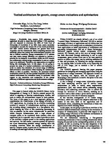
Since Fus are either processorcores or pre-designedunits, they cannot be controlled efficiently with a fine grain VLIW type instruction. Hence, a main controller (MC) is associatedwith each FU. This controller ensuresthe execution of correspondinginstructions that are stored in a local instruction memory (Fig. 1 0). More precisely, the partitioning and the scheduling of tasks or nodes of the data flow graph
IM: Instr. Memory MC: Main Contmller
Fig. 1 The consideredtargetarchitecture of the application [ lO],[ 1 l] provide coarse grain instruction segmentsfor each F’IJ. A coarse grain instruction contains information required to executethe operation: the location of the input or output data crosspointsin the communication network, indication of associatedprotocols to perform their transfers, and, if the unit supportsseveraloperations (for instance,FFT and FFT’), the op-code of the operation. The main controller sendsto the PU this instruction and wait for an end of execution before sendingthe next one. Since we consider applications with a static behavior, only a global loop involving all instructions is required in the main controller. In order to facilitate the I-N/SW system integration, we assume that all HW or SW Fus have this common interface with the network and the main controller. Therefore, input/output data transfers and PU’s computations are consideredto be internal to the NJ, controlled by a specific controller (Fig. 2 l ) or by a program memory of a core processor.This specific controller has in charge the managementof network protocols and control signals of the FU. l
Fig. 2 Controlstructureof functionalunits l
2.2
Communication
model
In the initial DSPA model, interconnection crosspoints are FIFO queues.This asynchronouscommunication model leads to an ASAP (As Soon As Possible) execution style of operationsby PUS.Since considered applications have a static behavior, a fixed scheduling of operations may be defined during partitioning. Then, some communications may be changed into synchronous transfers (rendez-vous mechanism) without overstepping timing constraints. The protocol associatedwith a transfer can be blocking or non blocking. The protocol is blocking if before reading or writing into a crosspoint the PIJ 24
must check availabilities of data. With a non blocking transfer no verification needsto be done. To limit the cost due to FIFOs, the static scheduleof tasks has to minimize the use of asynchronouscommunications. This point is addressedin the following section. 3.
Communication
synthesis
After partitioning communication edgesrepresentlinks between HW and SW units, between different SW units or different HW units. Communication synthesisconsists in determining for each communication edge the type of transfer (i.e. synchronousor asynchronous),the communication resources,the transfer protocol (blocking or non blocking) and the transfer mode (DMA or memory mapped I/O for processors).As mentioned above, the raw template architecture considers asynchronouscommunications with FIFOs. Hence, it is of prime importance to minimize their use in order to reduce communication resources.In the sequel,we addressthis point and details on other steps of the communication synthesisflow can be found in [6]. The communication synthesismethod assumesthat after partitioning a scheduleof tasks on FUs is provided. The aim is to transform asynchronouscommunications into synchronousones by local reschedulings. Fig. 3 a,b and c depict an example of a feasible reschedulingwhereasFig. 3 d,e and f illustrate the caseof an imposedasynchronouscommunication. l
l
tioned graph.
software unit hardware unit
b. Initial sc@d@ingof the graph without ~0mm~m~at~0noptumwt~on. e. A timing constraint is set up on task 7. . . synchronization loop c. With a synchronization between node 3 and 4 the communication becomessynchronous, without FIFOs.
Fig. 3 Local reschedulingof nodes
1. Reschedulingnode 5 is not feasible.
l
The algorithm is basedon two functions: Nodecharacterization and Edge-characterization. For each node Vi Node-characterizationcomputesthe mobility interval AMaVidefined as the interval betweenthe ASAP starting time ~(AsAp)iand the LAP ending time te(Aup)i : A~-vi = [fs~AsAp)i,fe(A~p)j].COmputations of interval mobilities take into account timing constraints.*Edge-characterizationco.nfputes the mobility interval AMei,j of a communication edge ei,! and its moblhty value Mei,j. The mob&y mterval representsall the instants where a communication between two nodes Vi and Vj can take place: AMei,i= [fs(ASAP))fe(A/!.AP)i]*The value ?s(ASAP)jrep resentsthe ASAP starting time of the node that receivesdata and the value te(Aup)j rep resentsthe ALAP ending time of the node that sendsdata. The mobility ValUe Mei,j iS equal t0 te(Aup)i - tS(~s~pa. If ?s(ASAP)j > te(Aup)i then Mei,j iS IlegatiVe and the communication is asynchronoussince there is no timing overlap betweenthe senderand the receiver. Otherwise the communication in consideredas potential synchronous. The Edge-characterizationfunction also provides a cost value 5eij for edgeswith a potential synchronous communication and representsthe ratio of the amount of data that is transferred through this edge (volume of communication Veij) and its mobility value: &i,j = Vey / Meij. Edgesthat have the highest cost value are consideredfirst iince if communications associatedwith these edges are synchronousa better hardwareminimization is expected. The algorithm (Fig. 3 0) operatesas follows. Firstly, nodes and edgesare characterized.An edge eij is labelled when a transfer type (synchronous or asynchronous)is assigned.Edges with asynchronous comnnmications(ts(ASAp)j> tc(mp)i i.e., Meij end (ps) operators 0 0 -> 86 FFr 1 87 -> 5.58 2 5.59-> 1288 3 1289-> 1758 4 1759-> 1820
-_ --__ --_-_____-----
!7.2...7.8l
_---
Fig. 5 Flow graphof GMDFa andpartitioning l
1 2456->...->57431 5744-> 5840 PPT,Adder FFT, Adder 5840ps
I
denceconstraintsbetweentwo nodesare expressedby an edge. On each edge,the name and the volume of data are given. A dotted line meansthat this data will be used at the next iteration of the algorithm. Node 0 computesan FFI on the input signal (XT). Node 1 is a normalization block. The output of node 2 gives the estimatedoutput in the frequency domain (Qx which denotesarrays Qr and Qi of complex values)by a convolution product, and after an FFT’ (node 3), we obtain the estimatedoutput in the time domain (Ytest). The difference betweenthe desired output (YT) and the estimatedoutput is calculated in node 4. Node 5 provides the echo (YF). Node 6 transforms the error signal (Et) into an error signal in the frequency domain (Ex) by one FFT. In nodes 7.i and 8.i, (i=l..k) filter coefficients are computed by FFT and FFT’ operationsof each elementary cells. In Fig. 5 * is given a HW/SW partitioning of the flow graph [ 1I]. This partitioning attemptsto minimize the hardware area with a timing constraint of 8 26
ms. The software unit is a DSP56002processorand the hardware part is composedof a FFlYoperator, an adder and two data memories Hr, Hi (Fig. 6 *.a). Before synthesisof communications all units are connectedthrough FIFOs placed in a network of six bus. The schedule of application nodes allows to label all communication edges with a synchronous transfer mode avoiding FIFOs. With the knowledge of timings of data transfers, a minimization of the number of bus can be performed (for example with a graph coloring method) and the network can be reducedto only two bus (Fig. 6 l .b). This example illustrates that the template architecture is designed All the crosspoint connecum now transfer mode
use the synchro-
cttmc interface
architecture Fig. 6
l
HW/SW architectures for GMDFa.
to support a general communication mechanismthrough FIFOs but the particularization induced by the knowledge of a specific application can lead to efficient implementations. 5.
Concluding
remarks
In this paper a generic architecture for HW/SW codesign methodologies is presented.Main characteristics of this model include asynchronousbehaviors of functional units with synchronizationson data arrivals, common encapsulationof functional units that allows easy extension capabilities and integration of heterogeneousHW/SW units. But the communication model can lead to excessivecommunication resources, therefore a communication synthesis method that performs local reschedulings of transfers,permits to replaceasynchronouscommunicationsinvolving FIFOs with synchronoustransfers supportedby bus. Our template architecture is therefore a good candidate model for codesign method-’ ologies dealing with applications with a static behavior. For applications with a dynamic behavior, important extensionsto this model are required and are area for future works. References
6.
Ill 121 [31 [41
151 161 [71
181 [91
I101 [ill 114 [131
AARTS E.H.L., ESSINK G., De KOCK E.A. Recursive bipartitioning of signal flow graphs for programmable video signal processors.Eurq~un Design and Test Conference, pages 460-466. Paris, March, 1996. ADAMS .I. K. and THOMAS D. E. The Design of Mixed Hardware/Software Systems. DAC. Las Vegas, NV, USA, june, 1996. BUCK J., HA S., LEE E.A., MESSERSCHMI’IT D.G. Ptolemy: a framework for simulating and prototyping heterogeneous systems. Int. Journal of Computer Simulation: special issue on Simulation Sofhvare Development. 4april.1994. CORPORAAL H., HOOGERBRUGGE J. Cosynthesis with the MOVE framework. CESA’96 IMACS Multiconference, pages 184-189. Lille, France, july, 9-12, 1996. ERNST R., HENKEL J., BENNER T. Hardware-Software Cosynthesis for Microcontrollers. IEEE Joumuf Design and Test of Computers. 64-15, december, 1993. GOGNIAT G. Etude de la synthese des communications dans les systemes 1ogicielsAnaten’els. Technical Report RT96-01, I3S, Sophia-Antipolis, France, juillet, 1996. GUPTA R.K., DE MICHELI G. Hardware-Software Cosynthesis for Digital Systems. IEEE Journal Design and Test of Computers. 29-41, September,1993. JEGOU Y., SEZNEC A. Data synchronized pipeline architecture: pipelining in multiprocessor environments. Journal of Parallel and Distributed Computing. 3508-526, 1986. KALAVADE A., LEE E. A global criticality/local phase driven algorithm for the constrained hardware/software partitioning problem. Proceedings Int. Workshop on Hardware-Software Co-Design, pages 42-48. Grenoble, France., September 22-24, 1994. KALAVADE A., LEE E. The extended partitioning problem: hardware/software mapping and implementation-bin selection. Proceedings Int. Workshop on Rapid System Pmtolyping, pages 12- 18. Chapel Hill, NC, June 7-9.1995. ROUSSEAU I?, BENZAKKI J., BERGE J.M., ISRAEL M. Adaptation of force-directed scheduling for hardware/ software partitioning. Proceedings Int. Workshop on Rapid System Prototyping. Chapel Hill, NC, June 7-9, 1995. SRIVASTA M.B., BRODERSEN R.W.,. SIERA: A Unified Framework for Rapid-F’rototyping of System-Level Hardware and Software. IEEE Transactions on Computer-Aided Design. 14(6):676-693, June, 1995.
VAHID E, GONG J., GAJSKI D. A binary-constraint searchalgorithm for minimizing hardware during hardware/ software partitioning. IEEE CS Press (editor), Pmt. European Design Automatton Conference. 1994.
27