University of California at San Diego. ABSTRACT. Autostereoscopic ...... REFERENCE. [1] N. Dodgson, J. Moore, S. Lang, G. Martin, P. Canepa. A 50” time-.
A GPU Sub-pixel Algorithm for Autostereoscopic Virtual Reality 1
1
1
1
2
2
Robert L. Kooima , Tom Peterka , Javier I. Girado , Jinghua Ge , Daniel J. Sandin , Thomas A. DeFanti
1
Electronic Visualization Laboratory
2
California Institute for Telecommunications and Information Technology
University of Illinois at Chicago University of California at San Diego ABSTRACT Autostereoscopic displays enable unencumbered immersive virtual reality, but at a significant computational expense. This expense impacts the feasibility of autostereo displays in highperformance real-time interactive applications. A new autostereo rendering algorithm named Combiner addresses this problem using the programmable vertex and fragment pipelines of modern graphics processing units (GPUs). This algorithm is applied to the Varrier, a large-scale, head-tracked, parallax barrier autostereo virtual reality platform. In this capacity, the Combiner algorithm has shown performance gains of 4x over traditional parallax barrier rendering algorithms. It has enabled high-performance rendering at sub-pixel scales, affording a 2x increase in resolution and showing a 1.4x improvement in visual acuity. CR categories: I.3.7 [Computer Graphics]: Three-Dimensional Graphics and Realism --- virtual reality Keywords: autostereoscopic display, 3D display, virtual reality, Varrier, parallax barrier 1
INTRODUCTION
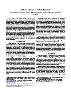
Unencumbered immersive stereo display is a clear goal of virtual reality research. Autostereoscopic displays achieve the goal of removing encumbrances, but the application of autostereo to virtual reality is not yet widespread. Existing autostereo displays are limited in performance and resolution. Our work seeks to improve upon the current state of autostereo displays in these areas in order to enhance the use of autostereo in the context of virtual reality. We define virtual reality by four criteria: tracked first-person perspective, orthostereo display, immersive field of view, and real-time interactivity. The working platform for our research is the Varrier (Figure 1), a display satisfying all four of these criteria, first introduced to the IEEE VR community at the IEEE Virtual Reality Conference 2004 [8]. From this platform we develop a new approach to the computational problem of autostereo display, a GPU-based algorithm named Combiner. The Combiner algorithm is a highperformance generalized rendering solution applicable to a large class of autostereo displays. In support of this claim, we begin by laying out a brief taxonomy of autostereo technologies. 2
Figure 1. The Cylindrical Varrier, a high-resolution parallax-barrier autostereo VR display.
Spatial-multiplexing is an autostereo approach involving image interleaving. In its simplest form, image interleaving entails cutting source images into strips and merging these strips into a single displayed image. A trivial example is shown in Figure 2. A significant issue with spatially-multiplexed autostereo is clearly seen in this figure. At most half of the pixels of each source image appear in the final interleaving. Consequently, at least half of the resolution of these images is lost.
BACKGROUND
Autostereoscopic displays fall largely into two categories: timemultiplexed and spatially-multiplexed. Time-multiplexed displays function by rapidly alternating between multiple images. They use a synchronous mechanism to ensure that a user’s views of these images are correspondingly occluded or clear. Such systems require delicate timing and rapidly responding displays. Time multiplexed displays include the Cambridge display [1] and the NYU display [6]. We focus here on the other category.
Figure 2. Spatial multiplexing of two views
The spatially-multiplexed category of displays is further divided into two functionally equivalent display types, distinguished by the means with which they direct interleaved images toward the eye. These are lenticular and parallax barrier displays. A lenticular display (Figure 3, right) uses a fine array of lenses to focus distinct portions of each image toward the user’s eyes. A parallax barrier display (Figure 3, left) uses a screen of opaque lines mounted a small distance from the surface of the display. This line screen occludes or reveals distinct portions of the image to each of the user’s eyes. Lenticular displays include the SynthaGram [5] and the Phillips 3D-LCD [10]. Parallax barrier displays include the 4D-Vision [9] and the Varrier [8]. Being equivalent, we choose to focus this discussion on parallax barriers, with the understanding that these concepts are universal to the category of spacially-multiplexed displays.
On a head-tracked two-view system we use a duty cycle around ¾. Our system displays bands of image pixels separated by guard band pixels, areas of black that reduce crosstalk and “ghosting” between stereo channels, enabling orthostereo and mitigating the occurrence of pseudostereo on tracker lag. A two-image interleaving consists of 4 bands in this order: a band of left-eye image, a guard band, a band of right-eye image, and another guard band. Given that exactly one of these should be visible from any given viewpoint, the ¾ opaque duty cycle follows. The optical thickness (t) parameter gives the distance from the parallax barrier to the display, adjusted to account for the index of refraction of the material to which the barrier is applied. The angle (a) parameter gives the physical barrier’s degree of rotation from vertical. On the Varrier [8], as on the SynthaGram [5] and the Philips 3D-LCD [10], image bands are non-vertical. The angle is selected empirically to maximize image quality and reduce moiré interference. The final line screen parameter, shift (s), gives the horizontal offset of the parallax barrier relative to the display.
Figure 3. Interleaved images displayed on parallax barrier (left) and lenticular (right) autostereoscopic displays
Figure 4. Line screen parameters
Autostereo displays in general can be further categorized as tracked and untracked. A tracked display has the advantage of providing a true first-person VR perspective and requires the integration of only two viewpoints. An untracked multi-image display generally provides some 3D look-around, but must render a large number of views to do so. An untracked 2-image display requires that the viewer remain motionless at a precise location. With our emphasis on VR, we focus strictly on tracked autostereo display, though a simple untracked modification to the work discussed here is touched upon below. Autostereo image interleaving is seldom as simple as depicted in Figure 2. The precise nature of the image interleaving is determined by the configuration of the line screen. A variety of algorithms of varying power, complexity, and performance have been documented. Most autostereo hardware literature includes discussion of the software methods appropriate to it. Examples include the computer-combining method of phscologram creation [7], the “punch texture” method of the 4D-Vision [9], and the “Interzig” process of rendering to the SynthaGram [5].
2.2 Traditional image-interleaving algorithms To render to a parallax barrier display, an application uses the line screen configuration and eye positions to determine which onscreen pixels are visible to each eye, and interleaves rendered views of the scene according to each pixel’s visibility. Many parallax barrier display algorithms and implementations exist. Three general approaches are common. The deferredrendering approach proceeds in two passes. First each view of the scene is rendered and stored off-screen, and second the image pixels are sorted and transferred to the final interleaved image. The alternative direct approach selectively writes each image to the interleaved image as it is generated. A hybrid approach alternates off-screen and on-screen passes, rendering each view to an off-screen buffer and selectively transferring it to the final image interleaving before proceeding with the next view. Static image and untracked displays, such as phscolograms [7] and the Synthagram [5], are obviously amenable to the deferred approach. The NYU display requires the deferred approach in order to satisfy a difficult timing requirement in the hardware implementation [6]. The 4D-Vision implements the deferred approach, but suggests the hybrid [9]. The Varrier traditionally uses the direct approach [8].
2.1 Line screen parameters A line screen configuration for a head-tracked parallax barrier display consists of five constants: pitch, duty cycle, optical thickness, angle, and shift. These values, along with the varying values of the user’s eye positions relative to the display, fully determine the state of the image interleaving at any given moment. The pitch (p) parameter gives the spatial frequency or period of the parallax barrier. Referring to Figure 4, p = 1 / (wo + wt). The duty cycle (c) parameter gives the barrier’s ratio of opacity to transparency. Below, c = wo / (wo + wt).
2.3 Varrier image-interleaving algorithms The Combiner algorithm builds upon the history of the Varrier. Three previous Varrier algorithms have been devised. The issues encountered and resolved by each of these show a clear progression, and a review of each algorithm, its rationale, and its limitations provides the context in which the Combiner algorithm can be described. Traditional Varrier rendering algorithms take the direct approach to the image-interleaving problem, drawing directly to
the on-screen frame buffer. They exploit the depth buffer to this effect. All of these algorithms draw the line screen as geometry, so the five configuration parameters defined above map onto 3D transformations in a straightforward fashion. These algorithms are distinguished from one another by the number of rendering passes made for each eye’s line screen and scene view. Thus they are named “1/1”, “3/3”, and “4/1”. The 1-line screen/1-scene pass (1/1) algorithm proceeds as follows. 1. 2. 3. 4. 5. 6.
Clear the color and depth buffers. Draw the line screen from the left eye’s perspective to the depth buffer at the near plane. Draw the scene from the left eye’s perspective to the color and depth buffers. Clear the depth buffer. Draw the line screen from the right eye’s perspective to the depth buffer at the near plane. Draw the scene from the right eye’s perspective to the color and depth buffers.
In effect, the pre-rendering of the line screen allows the depth buffer to protect those pixels of the color buffer that cannot be seen by the corresponding eye. The 1/1 algorithm either accepts or rejects each pixel entirely, potentially allowing errant un-occluded sub-pixels to remain visible, resulting in color shift. In addition, the one-pixel scale of the interleaving limits the pitch of the line screen to 4 times the size of a single pixel. To resolve either of these issues we must determine visibility at the sub-pixel level. The 3-line screen/3-scene pass (3/3) algorithm does this by rendering each color channel separately with the line screen shifted left or right by one third of a pixel. 1. 2.
3. 4.
5. 6.
Clear the color and depth buffers. From the left eye’s perspective, draw the line screen shifted left 1/3rd of a pixel to the depth buffer and draw the scene to the depth buffer and the red channel of the color buffer. From the left eye’s perspective, draw the line screen to the depth buffer normally and draw the scene to the depth buffer and the green channel of the color buffer. From the left eye’s perspective, draw the line screen shifted right 1/3rd of a pixel to the depth buffer and draw the scene to the depth buffer and the blue channel of the color buffer. Clear the depth buffer. Repeat steps 2 through 4 using the right eye’s perspective.
This algorithm works by simply repeating the action of the 1/1 algorithm 3 times, once for each channel of the destination frame buffer. The RGB sub-pixel centers are displaced by 1/3rd of a pixel from the pixel centers, so a virtual line screen behaves as desired when its shift parameter is displaced ±1/3rd of a pixel. The 3/3 algorithm correctly determines sub-pixels visibility, but it does so at significant cost. It makes one scene pass per channel per eye, so it consumes 3 times the fill rate of the 1/1 algorithm and requires a total of 6 passes over the scene’s geometry. The 4/1 algorithm attempts to resolve some of the performance issues of the 3/3 algorithm while retaining its quality. It works by rendering the left-eye view of the scene normally and selectively clearing the depth and color buffers in preparation for rendering the right-eye view. The rendering of the right eye view proceeds with the left-eye view protected by the depth buffer. Finally, the right-eye view of the line screen is drawn to the color buffer to
carve out the guard bands between the views. The left-eye and right-eye views of the scene are protected by the depth buffer, which by this time contains both the left-eye and right-eye views of the line screen. In summary, the 1/1 algorithm interleaves views giving autostereo, the 3/3 algorithm resolves the color issue, and the 4/1 algorithm minimizes the geometry expense and mitigates the pixel fill cost. We are left with a significant pixel fill cost due to the ¾ duty cycle. In effect, only 25% of all scene pixels processed are actually displayed. The remaining pixels comprise the line screens, which are touched once per channel per eye. This amounts to 75% of the pixel cost of touching every pixel on the screen 6 times per frame. While it is true that pixel fill rate continues to increase dramatically with each new generation of video hardware, a 6x overdraw penalty is a clear disadvantage to autostereo display, and is an obvious target for optimization. 2.4 OpenGL and GLSL As the complexity of graphics hardware increases, graphics software APIs become unwieldy. The fixed-function OpenGL API is not sufficiently rich to describe the extended capability provided. User-programmable functionality has evolved to replace fixed functionality in areas of deep complexity. In particular, the OpenGL Shading Language (GLSL) has arisen as a standard, widespread, high-level mechanism enabling the expression of specialized vertex and fragment processing [2]. This generalized processing capability enables a highly optimized solution to the problem of autostereo view interleaving. Both the programmable vertex pipeline and the programmable fragment pipeline are exploited. The vertex pipeline maps realworld spatial coordinates onto the parallax barrier, while the fragment pipeline determines each pixel’s status within the image interleaving relative to that barrier. All of this processing is performed by the GPU, freeing the CPU to attend to the needs of the application while ignoring the details of the display. 3
THE COMBINER ALGORITHM
3.1 Concept The Combiner algorithm differs from previous Varrier algorithms in that it chooses the deferred rendering approach over the direct. Rather than carefully composing all scene views to a single frame buffer, Combiner renders each view to a separate off-screen buffer and combines them to the display in a single final pass. Rather than explicitly drawing the virtual barrier, it computes the opacity of the virtual barrier as viewed by each eye and modulates each image accordingly. This has a number of advantages. First, the distinction between the off-screen render buffer and the on-screen display buffer affords the opportunity to render the scene at a resolution different than that of the display. For example, given a ¾ duty cycle, on average only one of every four scene-pixels is ultimately visible. The other three need not be rendered. To enable this, the off-screen render buffers are allocated at a reduced resolution more-closely matching the real output resolution of each image. This optimization is fairly obvious, and is used by other autostereo implementations, including [9], but it integrates particularly well with the use of GLSL. A simple texture coordinate scaling stretches off-screen buffers up to the full size of the display while they are combined to form the final on-screen interleaving. In general, this scaling factor need not be related to the display’s duty cycle, and it need not be applied only along the axis of the line screen. It represents a smoothly varying two-dimensional quality coefficient that
directly balances pixel fill-rate consumption versus visual fidelity. Due to the resolution-degrading nature of parallax barrier autostereo, these quality coefficients rarely need to be set to their maximum values to achieve optimal output quality. Second, the Combiner algorithm performs the final image interleaving for the entire frame in a single pass, touching each on-screen pixel exactly once. This, along with the reduction in pixel fill consumption reclaimed using the scaled off-screen buffers, reduces the total fill rate cost of autostereo display to its minimum. The overall performance is equivalent to quadbuffered, passive, or anaglyphic stereo on the same hardware. This significant reduction in the cost of sub-pixel autostereo image interleaving has lead to a potential increase in Varrier line screen pitch and, correspondingly, display resolution, with an associated increase in visual acuity. Third, the Combiner algorithm requires very little OpenGL state to be in effect during the execution of the application’s display function. Traditional algorithms have specific requirements with respect to the state of the depth and color buffers. This deprives the application of the freedom to exploit this OpenGL state as needed. The Combiner algorithm requires only that application render to an off-screen buffer. While the Combiner’s final pass does require GLSL state, this need not be in effect during the execution of the application’s display function, and the application is free to use GLSL state as needed. This reduced set of requirements significantly eases the porting of existing OpenGL applications to the Varrier display. 3.2 Line screen transform The line screen configuration with the positions of the user’s eyes fully determines the state of the image interleaving at any given moment. During the final combination of each frame, the eye positions are received from the tracking mechanism and a pair of matrices is constructed. These matrices transform a point in space to a position in the line screen, one matrix giving the line screen position as viewed by the left eye, and the other as viewed by the right eye.
Figure 6. Line screen space
The matrix construction is performed once for each eye. To begin, we compute a few intermediate values. These values require division by the z coordinate of the eye position. As such, they are akin to perspective projection. Let v be the 3D position of an eye in display space. We first compute the parallax offsets along the x and y axes due to optical thickness.
d x = tv x / v z d y = tv y / v z We also compute the reduction in line screen pitch and shift due to optical thickness. ! In effect, these are the apparent pitch and shift of the line screen after being displaced by the optical thickness along the ! normal of the display.
p" = p(v z # t) / v z s" = s(v z # t) / v z The line screen transform involves a scaling, a rotation, and a translation. The ! scaling accounts for the line screen pitch. The rotation accounts for the line screen angle. The translation accounts for ! the line screen shift and the parallax due to eye position. The line screen transform is the composition of these.
# p" % 0 M =% %0 % $0
! Figure 5. Display space, a real-world coordinate system centered upon and oriented with the display.
We define display space (Figure 5) as the coordinate system with its origin at the center of the display, oriented with the x and y axes of the display, using the same real-world unit of measure as the tracking system. We define line screen space (Figure 6) as a one-dimensional coordinate system where the axis maps onto position across the line screen. Using the line screen pitch as unity, this becomes the coordinate system of the line screen duty cycle parameter. In this space, the line screen appears as a rectangular wave and position within the line screen maps onto the phase of that wave.
0 p" 0 0
0 0 1 0
0& # cos a *sin a ( % 0( % sin a cos a ) 0( % 0 0 ( % 1' $ 0 0
0 0 1 0
0& #1 ( % 0( % 0 ) 0( % 0 ( % 1' $ 0
0 1 0 0
0 d x * s"& ( 0 dy ( 1 0 ( ( 0 1 '
3.3 Render setup Applications transmit input to GLSL shaders via uniform variables. Generally this involves naming the variable in the shader text and acquiring a descriptor locating said named variable via the OpenGL shader objects API [4]. When transmitting matrix uniforms such as the line screen transform we are afforded a shortcut. We exploit OpenGL texture matrices to communicate line screen transforms to the vertex shader. OpenGL transform functions act on these matrices directly, performing the necessary matrix multiplication. The resulting matrix values are transmitted automatically to an array of predefined uniform variables named “gl_TextureMatrix” in GLSL, eliminating the need to acquire and assign the value in code [2]. The left-eye off-screen buffer is bound to texture unit 0 and the left-eye transformation is composed on the TU0 texture matrix stack. Similarly, the right-eye image and transformation are bound to TU1. An orthogonal projection matrix is configured to map
display space onto normalized device coordinates and the final image interleaving is drawn as a single screen-filling rectangle.
uniform uniform uniform uniform
3.4 Vertex shader The vertex shader executes once for each of the four vertices of this rectangle. In so doing, it computes the line screen phase of each corner of each RGB channel of the display for both eyes. The shader receives a uniform constant giving the offset between sub-pixel centers. The output is a pair of phase values for each channel, stored in varying vector values for use by the fragment shader. The full source of the vertex shader follows. Shader source is shown here in order to emphasize the simplicity and compactness of the technique, and the straightforwardness of its application using GLSL.
samplerRect samplerRect float vec2
L_map; R_map; c; q;
varying vec3 L_phase; varying vec3 R_phase; void main() { vec4 L = textureRect(L_map, gl_FragCoord.xy * q); vec4 R = textureRect(R_map, gl_FragCoord.xy * q); vec3 Lk = step(vec3(c), fract(L_phase)); vec3 Rk = step(vec3(c), fract(R_phase)); vec3 Ik = max(L.rgb * Lk, R.rgb * Rk);
uniform vec3 offset; varying vec3 L_phase; varying vec3 R_phase;
gl_FragColor = vec4(Ik, 1.0); void main() { vec4 dr = gl_Vertex + vec4(offset.r, 0.0, 0.0, 0.0); vec4 dg = gl_Vertex + vec4(offset.g, 0.0, 0.0, 0.0); vec4 db = gl_Vertex + vec4(offset.b, 0.0, 0.0, 0.0);
}
L_phase.b = (gl_TextureMatrix[0] * db).x; R_phase.b = (gl_TextureMatrix[1] * db).x;
The final pixel is taken to be the maximum of the modulated left-eye and right-eye pixels. Under normal circumstances the sum of these pixels produces the same result. The use of the maximum function in this case is motivated by an edge-case behavior of parallax barrier displays. The pitch of the line screen limits the usable area of a display [8]. When the user moves outside of this area a clean separation of left-eye and right-eye visibility becomes impossible, and the image bands overlap. The sum of a pair of overlapping images tends to saturate to white, while their maximum preserves the color of the scene. The autostereo effect is necessarily lost under these circumstances, but the maximum function at least mitigates the jarring visual discontinuity.
gl_Position = ftransform();
4
L_phase.r = (gl_TextureMatrix[0] * dr).x; R_phase.r = (gl_TextureMatrix[1] * dr).x; L_phase.g = (gl_TextureMatrix[0] * dg).x; R_phase.g = (gl_TextureMatrix[1] * dg).x;
RESULTS
}
Note that the incoming vertex position attribute is used in two different ways. First, the line screen transform gives the line screen phase need for image interleaving. And second, the orthogonal projection, evaluated by the ftransform function, gives the normalized device coordinates needed for rasterization. By specifying vertex positions in display coordinates, both of these requirements are satisfied. 3.5 Fragment shader GLSL varying variables form the means of communication from vertex to fragment shaders. Values written by the vertex shader are linearly interpolated across the primitive being rasterized, and the resulting interpolated value is read by the fragment shader. This mechanism interpolates the left-eye and right-eye line screen phases for each channel across the screen-filling rectangle, giving a left-eye and right-eye line screen phase for each channel of each on-screen pixel. Left-eye and right-eye image pixels are sampled from offscreen render buffers bound as textures. Texture coordinates are given by the current fragment coordinate scaled by the quality factor to account for the difference in the sizes of the off-screen and on-screen buffers. The visibility of each channel of the left-eye and right-eye images is determined simply by comparing the fraction of the phase of the line screen of each channel with the duty cycle fraction. The step function maps the result of this comparison onto 0 or 1 per channel. The resulting RGB vectors modulate the lefteye and right-eye pixels, and the final interleaved image is a combination of these.
4.1 Performance Real-time update is necessary for immersion, so graphics performance is critical to virtual reality applications. Head-tracked autostereo in particular degrades at low update rates due to the occurrence of psuedostereo when the image interleaving lags the user position. The Combiner algorithm makes significant improvements in performance. To quantify this, the update rates of a variety of applications are tested using a number of autostereo modes.
Figure 7. Performance test applications: relief-mapped terrain, polygonal terrain, stereo video playback, and basic 3D.
“Puget Sound” (Figure 7, top-left) renders a 4K-by-4K terrain using a relief-mapping shader, which is pixel-fill-limited. “Crater Lake” (Figure 7, top-right) renders terrain as triangles, and is geometry-limited. Two versions of the Crater Lake data set are used, one with 172K vertices and another with 306K. “4D Julia” (Figure 7, bottom-left) plays a 1024-by-512 stereo video, a common application of non-VR autostereo systems. Finally, “Cow” (Figure 7, bottom-right) displays a model with 3K vertices, an easy task to be performed as fast as possible. All of these demos are implemented in Electro, a VR application scripting system supporting a wide variety of display types [3]. The six display modes evaluated here allow a number of comparisons to be made. Monoscopic mode gives a baseline performance for each application. Anaglyphic mode is basic stereo, representing performance on active and passive stereo systems common today. 1/1 and 3/3 are the traditional Varrier algorithms described above. Finally, the Combiner algorithm is run at 40% quality, a subjective “good enough” setting, and 100% quality. All of these tests are run on a single-panel Varrier based on a 30-inch LCD with a resolution of 2560 by 1600. Each test is run on both an NVIDIA Quadro FX3000 and an NVIDIA GeForce 7900GTX. The 7900GTX represents modern hardware with mature GLSL support while the FX3000 indicates performance on previous generation hardware. Table 1. Performance test results run on an NVIDIA Quadro FX3000. All numbers in frames per second.
Comb Comb 40% 100% 6 6
Mono 15
Ana 8
1/1 7
3/3 2
9
4
4
1
4
4