Hindawi Publishing Corporation The Scientific World Journal Volume 2013, Article ID 464107, 7 pages http://dx.doi.org/10.1155/2013/464107
Research Article A Graph Theory Practice on Transformed Image: A Random Image Steganography V. Thanikaiselvan,1 P. Arulmozhivarman,1 S. Subashanthini,2 and Rengarajan Amirtharajan3 1
School of Electronics Engineering, VIT University, Vellore 632014, India School of Information Technology, VIT University, Vellore 632014, India 3 School of Electrical & Electronics Engineering, SASTRA University, Thanjavur 613401, India 2
Correspondence should be addressed to Rengarajan Amirtharajan;
[email protected] Received 15 August 2013; Accepted 3 October 2013 Academic Editors: R. Lu and G. Z. Zhao Copyright © 2013 V. Thanikaiselvan et al. This is an open access article distributed under the Creative Commons Attribution License, which permits unrestricted use, distribution, and reproduction in any medium, provided the original work is properly cited. Modern day information age is enriched with the advanced network communication expertise but unfortunately at the same time encounters infinite security issues when dealing with secret and/or private information. The storage and transmission of the secret information become highly essential and have led to a deluge of research in this field. In this paper, an optimistic effort has been taken to combine graceful graph along with integer wavelet transform (IWT) to implement random image steganography for secure communication. The implementation part begins with the conversion of cover image into wavelet coefficients through IWT and is followed by embedding secret image in the randomly selected coefficients through graph theory. Finally stegoimage is obtained by applying inverse IWT. This method provides a maximum of 44 dB peak signal to noise ratio (PSNR) for 266646 bits. Thus, the proposed method gives high imperceptibility through high PSNR value and high embedding capacity in the cover image due to adaptive embedding scheme and high robustness against blind attack through graph theoretic random selection of coefficients.
1. Introduction Communication has become inevitable in everybody’s routine life. Be it mails, texts, photos, or audios or videos, they get communicated in millions among billions. This in turn demands only one thing, that is, security. Information security plays pivotal role to keep the information safe. Among the prominent definitions for information security, the most vital of them is information security which is about veracity, discretion, and data availability. Though several successful methods exist, they are still in research to boost up their performance. Undoubtedly, information security is the soul of exchange of data. Steganography [1] and cryptography [2] have evolved from times immemorial to provide security for communicating secret details with steganography being the recent one. Image steganography [3–7] is a very interesting field because of the imperceptible way of hiding data due to the resolution of the eye. Image hiding algorithms are used to embed secret
data with higher efficiency and less detecting capability [8]. It typically involves encrypting the secret images at first and then embedding the secret information into encrypted images. These in turn have stronger antiattack capability than normal cover image [9]. Image steganography can be done either in spatial domain [10–14] or in frequency domain [15–18]. LSB (least significant bit) embedding [11] is a technique for embedding secret information into a cover image. A mathematical model for LSB technique has been developed for embedding and extracting the secret data [11]. PVD (pixel value differencing) [9, 12] is an efficient technique for spatial domain steganography, which provides high data embedding capacity with reasonable PSNR. PVD is a quite common technique for steganography. Numbers of variations and new methods have been developed for PVD based steganography. The present spatial and transform domain techniques for steganography employ raster scan procedure but are not able to provide high
2
The Scientific World Journal
security as data can be extracted easily with blind stegoattack. Solution to this problem is to adopt random steganography [10, 12], which is a new method for escaping from blind stegoattacks because embedding will be done in random manner. This steganography method enhances the security for secret data with the existing steganography algorithms. Pixel indicator method [10] is a random steganography method which is used to select the cover image pixels randomly for embedding and to decide the number of bits to be embedded in the selected pixel. Thus, the robustness of any existing algorithm can be improved by adopting random selection of pixels. In the transform domain steganography, cover image pixels are converted into coefficients by applying any one of the two-dimensional transforms. Transform coefficients work as a carrier of the secret data in the frequency domain. Three transforms, namely, discrete cosine transform (DCT) [17], discrete wavelet transform (DWT) [16], and IWT [15, 18], are the important transforms for data hiding. The LSB substitution is the broadly used technique in transform based steganography. Studying all the aforementioned available methods, a stable steganography method is preferred to be implemented in IWT domain, which offers better imperceptibility without compromising capacity and security by adapting graceful graph to select the coefficients randomly. This paper is structured as follows. Section 2 gives a view about integer wavelet transform and graceful graph is discussed in Section 3. Section 4 depicts the proposed methodology; Section 5 deals about the results and discussions. Section 6 demonstrates the steganalysis and finally Section 7 wraps up this work.
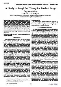
2. Integer Wavelet Transform The following Haar integer wavelet transform (HIWT) can be used to get the coefficients in integer form, and then the LSB substitution for steganography can be achieved by lossless manner. In this paper first level decomposition is adapted which results in approximation (𝐿𝐿1), horizontal (𝐿𝐻1), vertical (𝐻𝐿1), and diagonal (𝐻𝐻1) coefficients as shown in Figure 1. 2.1. One-Dimensional Decomposition Step 1. Process the image column-wise to get high pass filtered output (𝐻1) and low pass filtered output (𝐿1). The size of 𝐻1 and 𝐿1 is 𝑁 × 𝑁/2 𝐻1 = (𝐶𝑜 − 𝐶𝑒 ) , (1) 𝐻 𝐿1 = (𝐶𝑒 + Floor ( )) , 2 where 𝐶𝑜 and 𝐶𝑒 are the odd column and even column-wise pixel values. 2.2. Two-Dimensional Decomposition Step 2. Take 𝐻1 and 𝐿1 for getting the approximation (𝐿𝐿1), horizontal (𝐿𝐻1), vertical (𝐻𝐿1), and diagonal (𝐻𝐻1)
N × N = image
L
(a)
LL
LH
HL
HH
H
(b)
Figure 1: (a) Input image with size 𝑁 × 𝑁. (b) First level decomposition of the input image.
coefficients. Size of all four sets of coefficient is 𝑁/2 × 𝑁/2. Row-wise processing will be adapted here on 𝐻1 and 𝐿1. Separate the odd and even rows of 𝐻1 and 𝐿1 as follows: 𝐻odd —odd row of 𝐻1, 𝐿 odd —odd row of 𝐿1, 𝐻even —even row of 𝐻1, 𝐿 even —even row of 𝐿1. The following equations are used to get the 2D integer wavelet transform: 𝐿𝐻1 = 𝐿 odd − 𝐿 even , 𝐿𝐿1 = 𝐿 even + Floor (
𝐿𝐻 ), 2
𝐻𝐻1 = 𝐻odd − 𝐻even , 𝐻𝐿1 = 𝐻even + Floor (
(2)
𝐻𝐻 ). 2
3. Graceful Graph for Random Path Graph theory is the study of points and lines. In particular, it involves the ways in which the sets of points called vertices (𝑉) can be connected by lines or arcs called edges (𝐸). Any graph can be represented as 𝐺(𝑉, 𝐸). In the steganographic point of view, pixels or coefficients are considered as nodes and connection between two nodes is called edge. Graceful graphs play an important role for random traversing in steganography algorithms. 3.1. Procedure for Graph Generation. Since in the steganographic point of view the coefficients are considered as nodes and given the number of nodes (𝑁), following four sequences 𝑆1, 𝑆2, 𝑆3, and 𝑆4 can be formed as follows: 𝑆1 = [2𝑞, 2𝑞 − 1, 2𝑞 − 2, . . . , 𝑞 + 1] ,
(3)
where “𝑞” is an integer and calculated as 𝑞 = 𝑁/4. 𝑁 represents total number of nodes. 𝑁 should be multiple of 4: 𝑆2 = [𝑞𝑠 (1) + 𝜎 (1) , 𝑞𝑠 (2) + 𝜎 (2) , . . . , 𝑞𝑠 (𝑞) + 𝜎 (𝑞)] , (4) where 𝑞𝑠 (𝑖) is 𝑖th element of the sequence {𝑞, 𝑞 − 1, 𝑞 − 2, 𝑞 − 3, . . . , (𝑞 − 𝑁/4) + 1}, 𝜎(𝑖) is 𝑖th element of the sequence (𝜎) obtained by random arrangement of the elements of “𝑞𝑠 .”
The Scientific World Journal
3 12 11
5
1
12 9
5
4 9
8
3 6
15
14
13
14
13
7 1
15
0
10
3 2
7
6
10
4 Rm =
8
7 9 3 1
8 12 2 0
6 5 11 10 14 4 13 15
2
11 (a)
(b)
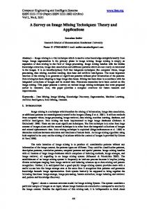
Figure 2: (a) Graceful graph. (b) Rm matrix. Table 1: Graceful graph table.
Node sequence (NS)
1
Edge numbering (E)
S
8
Addition A (A = E + S)
2
3
4
5
6
7
8
9
10
11
12
13
14
15
16
1
2
3
4
5
6
7
8
9
10
11
12
13
14
15
7
6
5
5
7
5
3
2
3
4
1
0
0
0
0
8
8
8
9
12
11
10
10
12
14
12
12
13
14
15
Sequence 𝑆3 is formed with the elements of “𝜎” as 𝑆3 = [𝜎 (𝑞) , 𝜎 (𝑞 − 1) , . . . , 𝜎 (1)] .
Step 3. Generation of sequence 𝑆3: substituting 𝜎 = [1 4 3 2] in (5), (5)
𝑆4 is a sequence containing “𝑞” zeros 𝑆4 = [0, 0, 0, . . .] .
(6)
(7)
A graceful graph table is generated by using node sequence (NS), edge numbers (𝐸), sequence “𝑆”, and a sequence “𝐴” (containing sum of elements of 𝐸 and 𝑆). Graph will be generated using this table. The entire graph generation is illustrated in the example given below. 3.2. Example for a Graph Generation. A simple example is taken for explanation; this graph is generated by considering a 4 × 4 matrix containing 16 elements. Therefore, 𝑁 = 16. Step 1. Generation of sequence 𝑆1: consider an integer “𝑞”, is calculated by 𝑞 = 𝑁/4. Since 𝑁 is 16, 𝑞 = 4. 𝑆1 is generated using (3): 𝑆1 = [8 7 6 5] .
(8)
Step 2. Generation of sequence 𝑆2: using (4), 𝑞𝑠 = [4 3 2 1], 𝜎 = [1 4 3 2] is a permuted sequence of 𝑞𝑠 : 𝑆2 = [5 7 5 3] .
(10)
Step 4. Generation of the sequence 𝑆4: since 𝑞 = 4,
The previous sequences are concatenated to form a new sequence “𝑆”: 𝑆 = [𝑆1 𝑆2 𝑆3 𝑆4] .
𝑆3 = [2 3 4 1] .
(9)
𝑆4 = [0 0 0 0] .
(11)
Step 5. Generation of sequence 𝑆: 𝑆 = [8 7 6 5 5 7 5 3 2 3 4 1 0 0 0 0] .
(12)
Step 6. Generation of a graceful graph table: Table 1 shows graceful graph table for random co-efficient selection. Steps to generate graceful graph table are as follows. Step 6.1. Generate the sequence NS based on the number of nodes (𝑁): NS = {1, 2, . . . , 𝑁}. Step 6.2. Generate the edge sequence 𝐸 = {1, 2, . . . , 𝑁 − 1} where the first element of sequence 𝐸 will fall below second element of the sequence NS and so on. Step 6.3. Arrange the 𝑆 sequence in Table 1 and remove the first element of 𝑆. Step 6.4. Compute the final sequence 𝐴 by adding the elements of 𝐸 and (𝐴 = 𝐸 + 𝑆). Step 7. Draw a graceful graph by considering the sequences 𝑆 and 𝐴. The elements of 𝑆 and 𝐴 are the nodes for the graph and are scanned in a zigzag manner as shown in Table 1
4
The Scientific World Journal Table 2: Results for various images.
Embedding only in LH1 Embedding only in HL1 Embedding only in HH1 Embedding in LH1, HL1, and HH1 subbands PSNR (dB) Total bits PSNR (dB) Total bits PSNR (dB) Total bits PSNR (dB) Total bits Lena 49.3802 85421 47.4721 98978 56.3353 71795 44.9682 256174 Baboon 44.4302 135275 44.5608 135123 54.0215 93587 41.315 363965 Cameraman 47.857 94815 47.3303 95353 55.4215 76498 44.2326 266646 Taj Mahal 46.8793 101949 46.8283 101515 55.9065 74440 43.6245 277884 Peppers 48.4761 90894 47.7119 95704 56.4168 71014 44.8319 257592 Barbara 45.3901 117307 42.8743 144540 49.1536 137097 40.3423 398924 Airplane 47.0608 99695 47.321 96611 55.7802 75529 43.9919 271815 Image
with another colour. Connection between the nodes is the edge with difference of the node numbers being the label for the edge. The graph generated is shown in Figure 2(a). A 4 × 4 matrix is generated by arranging the nodes in the increasing order of the labels. Repeating nodes will be discarded while generating the matrix; that is, the matrix should contain one node only once. The generated matrix is named as “Rm” (random matrix) and shown in Figure 2(b). This Rm is considered as key 2 in this methodology. In the matrix “Rm” element 0 represents the position of the coefficient to be embedded first and 15 represents the position of the co-efficient to be embedded at last.
Step 4. Segment the image into 16 × 16 sized blocks. Step 5. Read all the 16 × 16 blocks one by one from top to bottom and assign numbers to all the blocks as per raster scan procedure. Step 6. Generate a random number sequence (RS) that contains unique positive integers between 1 and 1024 with the length 1024 (because the cover image is segmented into 1024 blocks of 16 × 16 size). This sequence is used to select the 16 × 16 blocks randomly. This is considered as Key1. If the first element of RS is 3 then the 3rd block will be selected first for embedding
4. Proposed Methodology Figure 3 shows the proposed methodology for highly random and robust steganography. First the cover image is given to histogram modification section to change the pixel values between 15 and 240. Then we segment the cover image into 16 × 16 nonoverlapping blocks and apply the integer wavelet transform. Then key 1 is used for selecting a particular 16 × 16 block, key 2 generated using graceful graphs is used to select the coefficients, and key 3 is the number of bits to be embedded in the selected coefficients. Finally, inverse IWT is applied to construct the stegoimage. 4.1. Embedding Algorithm Step 1. Consider a 512 × 512 grayscale image as the cover image (CI); then CI𝑖𝑗 ∈ {0, 1, 2, 3, . . . , 255} ,
(13)
where 𝑖 and 𝑗 are varying from 1 to 512. Step 2. Generate a secret data (SD). Here a stream of binary data is considered as secret data: SD ∈ {0, 1} .
(14)
Step 3. Apply histogram modification on the cover image to restrict the pixel values between 15 and 240. Now cover image is denoted as CI : CI𝑖,𝑗 ∈ {15, 16, 17, . . . , 240} .
(15)
RS ∈ {1, 2, 3, . . . , 255, . . . , 1024} .
(16)
Step 7. Apply Haar integer wavelet transform to the selected 16 × 16 block. It will result in four subbands as approximation (𝐿𝐿1), horizontal (𝐿𝐻1), vertical (𝐻𝐿1), and diagonal (𝐻𝐻1) coefficients (𝐶) with the size of 8 × 8. In this methodology, embedding will be done in all subbands except 𝐿𝐿1 subband to maintain good imperceptibility. Step 8. Three different Rm matrices (Key-2) will be generated with 𝑁 = 64 using graceful graph corresponding to 𝐿𝐻1, 𝐻𝐿1, and 𝐻𝐻1, subbands. Those matrices will be used to select the coefficients randomly in each subband. Step 9. Adaptive bit embedding procedure is adopted and the number of bits to be embedded in the selected co-efficient is given by “𝐿” (bit length) in (17). This is considered as key 3. Modulus of 𝐶 is considered in case it holds negative value. Consider 4, { { { {3, 𝐿={ { 2, { { {1,
𝐶 ≥ 16, if 8 ≤ 𝐶 < 16, if 4 ≤ 𝐶 < 8, if 𝐶 < 4.
(17)
Step 10. 𝐿 numbers of bits are taken from SD and embedded by using LSB [11] embedding procedure on the selected
The Scientific World Journal
5 Embedding algorithm
Cover image
Histogram modification
Selection of a block
Key 1
Secret Inverse IWT
Integer wavelet transform (IWT)
Adaptive and random data embedding
Image is segmented into 16 × 16
Key 2
Key 3
Stegoimage
Extraction algorithm
Stegoimage
Image is segmented into 16 × 16
Selection of a block
Key 1
Secret
Integer wavelet transform (IWT)
Secret data extraction
Key 2
Key 3
Figure 3: Block diagram of proposed methodology.
(a)
(b)
(c)
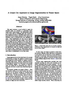
Figure 4: (a) cover image, baboon. (b) Stegoimage with 𝐻𝐻1 embedding. (c) Stegoimage with 𝐿𝐻1, 𝐻𝐿1, and 𝐻𝐻1 subband.
co-efficient (𝐶). Repeat this procedure for all the 𝐶 values and the remaining subbands. Step 11. Repeat Steps 7 to 10 for all the 16 × 16 blocks. Step 12. Apply inverse integer wavelet transform to each 16 × 16 block and produce the stegoimage (SI), SI𝑖𝑗 ∈ {0, 1, 2, 3, . . . , 255}, where 𝑖 and 𝑗 are varying from 1 to 512. 4.2. Extraction Algorithm. Exact reverse procedure should be used to extract the secret data. Step 1. Get 512 × 512 stegoimage SI𝑖𝑗 ∈ {0, 1, 2, 3, . . . , 255}. Step 2. Segment the image into 16 × 16 sized blocks.
Step 3. Use key 1 to select the 16 × 16 block. Step 5. Apply integer wavelet transform to the selected 16 × 16 block. This will result in approximation (𝐿𝐿1), horizontal (𝐿𝐻1), vertical (𝐻𝐿1), and diagonal (𝐻𝐻1) coefficients. Step 6. Use key 2 for random selection of coefficients in each subband. Step 7. Use key 3 for calculating the number of bits to be extracted [11] from the selected co-efficient. Step 8. Repeat the above procedure for all the 𝐶 values and all 16 × 16 sized blocks.
6
The Scientific World Journal Table 3: Comparative analysis.
Method
Total number of iterations to extract data (TI)
Proposed method Fazli et al. [16] Song et al. [17] Sakkara et al. [18]
(1024! ∗ 3! ∗ 64! ∗ 4 ∗ 64 ∗ 3) ∗ 1024 TI = 256 ∗ 256 ∗ 3 TI = 64! ∗ 64 TI = 16! ∗ 64 ∗ 64 ∗ 3
5. Results and Discussion Proposed method has been evaluated with seven images with the size of 512 × 512. The performance characteristics are evaluated through MSE (mean squared error) and peak signal to noise ratio (PSNR). PSNR is calculated by using the following equation (18), where 𝑀 and 𝑁 are the sizes of the given image:
MSE =
2 1 𝑀 𝑁 ∑ ∑ (𝐶𝑖,𝑗 − 𝑆𝑖,𝑗 ) , 𝑀𝑁 𝑖=1 𝑗=1
PSNR = 10 log10
to extract the hidden information from the stegoimage generated by the proposed method: Total number of iterations (TI) = (1024! ∗ 3! ∗ 64! ∗ 4 ∗ 64 ∗ 3) ∗ 1024,
(19)
where 1024! is the possible order of traversals among 1024 numbers of 16 × 16 sized blocks, 3! gives the possible order of the subbands in which the data is embedded, 64! represents different Rm matrices, 4 represents the maximum bit length. 64 represents the total number of coefficients in each subband, 3 represents the total number of subbands, and 1024 represents the total number of 16 × 16 blocks. The proposed methodology is compared with the existing techniques and the TI values are tabulated in Table 3. Thus, the large difference observed in the total number of iterations required for the proposed technique and the existing technique clearly elucidates the enhanced data security against blind attacks.
7. Conclusion (18)
255 ∗ 255 dB. MSE
Cover image is divided into 16 × 16 nonoverlapping blocks. Therefore, wavelet subband size is 8 × 8. Here, embedding is done with two different ways involving the embedding in one subband and embedding in all the subbands except 𝐿𝐿1. Key 1, key 2, and key 3 provide high security against blind steganography attacks or human visual attacks. All the results are tabulated in Table 2. For Lena image PSNR value is around 49 dB, 47 dB, and 56 dB when the data is embedded only in 𝐿𝐻1, 𝐻𝐿1, and 𝐻𝐻1, respectively. Embedding only in 𝐻𝐻1 subband resulted in PSNR above 50 dB. Maximum of 144540 bits are embedded in Barbara image with embedding only in 𝐻𝐿1. Technique of embedding data in only one subband shows high imperceptibility but less embedding capacity. However, the technique of embedding data in all the subbands except 𝐿𝐿1 results in increased number of bits with reasonable PSNR value around 44 dB, thus reflecting the advantage of IWT domain steganography. Figures 4(a), 4(b), and 4(c) show cover image, baboon, stegoimage with HH1 embedding, and stegoimage with 3-subband embedding. All the images are looking the same; therefore, this technique can escape from visual attack.
6. Steganalysis Steganalysis is the blind inspection of embedded data in stegoimage. This proposed method is highly robust against the blind attacks. This method is a transform domain method, so that secret data cannot be extracted from the spatial domain. Key 1, key 2, and key 3 impart high randomness for embedding. The following numbers of iterations are required
In the proposed work, IWT along with graceful graph offers a secure and random image steganography with high imperceptibility. Moreover, this adaptive random embedding process results in high capacity and robustness against blind attacks. Higher imperceptibility is attained when the data is embedded only in one subband, whereas higher capacity with reasonable PSNR is observed when the data is embedded in all the subbands except 𝐿𝐿1 subband. This proposed method can be enhanced by using different integer transforms to attain higher PSNR and robustness can be improved further by adding multiple security methods.
Conflict of Interests The authors of the paper do not have a direct financial relation with the commercial identity mentioned in this paper that might lead to a conflict of interests for any of the authors and declare that there is no conflict of interests regarding the publication of this paper.
References [1] S. Katzenbeisser and F. A. P. Petitcolas, Hiding Techniques for Steganography and Digital Watermarking, Artech House, Norwood, Mass, USA, 2000. [2] B. Schneier, Applied Cryptography Protocols, Algorithm and Source Code in C, Wiley India Edition, 2nd edition, 2007. [3] A. Cheddad, J. Condell, K. Curran, and P. Mc Kevitt, “Digital image steganography: survey and analysis of current methods,” Signal Processing, vol. 90, no. 3, pp. 727–752, 2010. [4] N. Provos and P. Honeyman, “Hide and seek: an introduction to steganography,” IEEE Security and Privacy, vol. 1, no. 3, pp. 32–44, 2003. [5] W. Bender, D. Gruhl, N. Morimoto, and A. Lu, “Techniques for data hiding,” IBM Systems Journal, vol. 35, no. 3-4, pp. 313–335, 1996.
The Scientific World Journal [6] B. Saha and S. Sharma, “Steganographic techniques of data hiding using digital images,” Defence Science Journal, vol. 62, no. 1, pp. 11–18, 2012. [7] R. Amirtharajan, J. Qin, and J. B. B. Rayappan, “Random image steganography and steganalysis: present status and future directions,” Information Technology Journal, vol. 11, no. 5, pp. 566–576, 2012. [8] R. Amirtharajan and J. B. B. Rayappan, “An intelligent chaotic embedding approach to enhance stego-image quality,” Information Sciences, vol. 193, pp. 115–124, 2012. [9] V. Thanikaiselvan, S. Malpani, and M. Garg, “New steganography for Crypto cover files,” International Journal of Engineering and Technology, vol. 5, no. 2, pp. 1594–1599, 2013. [10] R. Amirtharajan and J. B. B. Rayappan, “Brownian motion of binary, gray-binary and gray bits in image for stego,” Journal of Applied Sciences, vol. 12, no. 5, pp. 428–439, 2012. [11] C.-K. Chan and L. M. Cheng, “Hiding data in images by simple LSB substitution,” Pattern Recognition, vol. 37, no. 3, pp. 469– 474, 2004. [12] V. Thanikaiselvan, S. Kumar, N. Neelima, and R. Amirtharajan, “Data battle on the digital field between horse cavalry and interlopers,” Journal of Theoretical and Applied Information Technology, vol. 29, no. 2, pp. 85–91, 2011. [13] K. Thenmozhi, P. Praveenkumar, R. Amirtharajan, V. Prithiviraj, R. Varadarajan, and J. B. B. Rayappan, “OFDM+ CDMA+Stego = secure communication: a review,” Research Journal of Information Technology, vol. 4, no. 2, pp. 31–46, 2012. [14] S. K. Pal, P. K. Saxena, and S. K. Muttoo, “Designing secure and survivable stegosystems,” Defence Science Journal, vol. 56, no. 2, pp. 239–250, 2006. [15] V. Thanikaiselvan, P. A. Varman, R. Amirtharajan, and J. B. B. Rayappan, “Wavelet pave the trio travel for a secret mission— a stego vision,” in Global Trends in Information Systems and Software Applications, P. V. Krishna, M. R. Babu, and E. Ariwa, Eds., vol. 270 of Communications in Computer and Information Science, pp. 212–221, Springer, Berlin , Germany, 2012. [16] S. Fazli, S. Gholamrezaei, and A. Bazrafshan, “Advanced wavelet based steganography for colored images,” in Proceedings of the International Congress on Ultra Modern Telecommunications and Control Systems and Workshops (ICUMT ’10), pp. 377–380, October 2010. [17] X. Song, S. Wang, and X. Niu, “An Integer DCT and Affine Transformation Based Image Steganography Method,” in Proceedings of the 8th International Conference on Intelligent Information Hiding and Multimedia Signal Processing (IIH-MSP ’12), pp. 102–105, 2012. [18] S. Sakkara, D. H. Akkamahadevi, K. Somashekar, and K. Raghu, “Integer wavelet based secret data hiding by selecting variable bit length,” International Journal of Computer Applications, vol. 48, no. 19, pp. 7–11, 2012.
7