of a specific commercial platform when teaching the IEC 61131-3 standard for ... can also be used to fast prototyping automation systems using a desktop ...
A GRAPHICAL TOOL FOR DESIGN PORTABLE AUTOMATION SOFTWARE G. De Tommasi ∗ P. Di Sanzo ∗∗ A. Pironti ∗ ∗ Dipartimento di Informatica e Sistemistica Universit` a degli Studi di Napoli “Federico II” ∗∗ Universit` a degli Studi di Napoli “Federico II”
Abstract: UniSim is a graphical tool which can be used to avoid the choice of a specific commercial platform when teaching the IEC 61131-3 standard for programmable logic controllers. UniSim allows to develop automation software which is fully compliant with the standard, and to validate it via simulation. It can also be used to fast prototyping automation systems using a desktop equipped with low-cost commercial I/O boards. This prototype can be interfaced with a plant simulator to perform hardware-in-the-loop validation of the control system. c Copyright °2006 IFAC Keywords: IEC 61131-3, programmable logic controllers, fast prototyping, hardware-in-the-loop-validation.
1. INTRODUCTION Programmable logic controllers (PLCs) (Stenerson, 2004; Warnock, 1988) are widely used in modern industrial automation systems. When a new system has to be developed, the designers have to: • define the hardware architecture (controllers, sensors and actuators); • define the communications between all the devices; • assign one or more tasks to each control device; • define the data structures to be used in the code; • write the control code. Thus, an automation project includes the information about the control system configuration, the data and the code. The IEC 61131-3 standard (IEC 61131-3 International Standard, 2003; Ohman et al., 1998) specifies how an automation project should be struc-
tured, establishing what functionalities a programmable controller should have, and what programming languages should be available to the developers. Although the IEC standard has been introduced in 1993, only few companies produces devices which fully complies with the standard. In the most of the cases, students who have learned the IEC 61131-3 standard in a class, should be introduced to the platform available in their laboratory, before they can start to work with the automation system. UniSim is a graphical tool, distributed with a General Public License (GPL), which can be used to avoid the choice of a specific commercial platform when teaching programming for PLCs. UniSim allows to develop and validate automation software which fully complies with the IEC standard. It also helps the students to do fast prototyping of the automation systems, using a desktop equipped with low-cost commercial I/O boards. The prototype can eventually be interfaced with a plant simulator to perform hardwarein-the-loop validation (as it is shown the example
of Section 5). Moreover, UniSim make use of the XML Formats for IEC 61131-3 (PLCopen website, 2006) to import and export all the data related with the automation project. This feature give the possibility to reuse the developed software and test it on a commercial platform.
Producer of graphical and logical information
XML file XML file Other development tool
XML file Development tool
The current release of UniSim which is available at UniSim website (2006) is a work in progress version, therefore it has the following limitations: • only one resource can be specified in each project; • only two of the languages provided by the standard have been implemented (sequential functional chart (David, 1995) and ladder diagram); • only the program POU (program organization unit) has been implemented; • only boolean data type are allowed. This work describes the software structure and the functionalities of UniSim, and how it helps the teaching of the IEC 61131-3 standard in a class of industrial automation both for homework and lab activities.
Other development tool
XML file Consumer of graphical and logical information
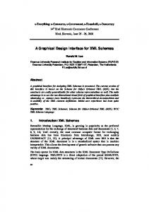
Fig. 1. Data exchange using XML files.
Fig. 2. The project element.
2. XML FORMATS FOR IEC 61131-3 The XML Formats for IEC 61131-3 schema is briefly introduced here, since the architecture of UniSim is strictly related to the data hierarchy specified by this XML schema. The XML Formats for IEC 61131-3 is an XML schema (van der Vlist, 2002), which provides an open interface for data exchange between different development tools. The first version of the XML Formats has been released on April 2005, by PLCopen (PLCopen website, 2006), which is a vendor and product independent organization. The main objective accomplished by this standard is to achieve portability of the automation projects between one development environment to another (see Figure 1). UniSim uses the XML Formats to import and export the automation projects, therefore the software developed with UniSim can be run on any IEC 61131-3 compliant device without changing the code or, at least, with only minor changes. 2.1 XML Elements The XML Formats schema defines a different element for each component of an automation project. A short overview of the schema structure is given next. More details can be found in PLCopen Technical Comittee 6 (2005).
Fig. 3. The types element. The project element shown in Figure 2 is the document root node and it holds four different elements: fileHeader, contentHeader, types and instances. The first two are used to store auxiliary information, such as the project version and the name of the tool that has generated the XML file. The types element (see Figure 3) defines the data types and the program organization units (POUs) used in the automation project 1 . Each pous element shown in Figure 3 has a body which can be specified using one of the five programming languages provided by the standard 2 . The instances element holds a list of configurations, wherein the resources elements are specified. A list of task with the corresponding POUs instances are associated with each resource (see Figure 4).
1
The IEC standard defines three types of POU: program, function and functional block. 2 Instruction List (IL), Structured Text (ST), Function Block Diagram (FBD), Ladder Diagram (LD) and Sequential Functional Chart (SFC).
Fig. 4. The resource element. 3. UNISIM - SOFTWARE ARCHITECTURE 3.1 Overview UniSim has been designed by using an objectoriented approach, and it has been developed on the Microsoft .NET platform (Microsoft .NET website, 2006). Fig. 5. UniSim simplified class diagram. 3
From the class diagram shown in Figure 5 , it can be noticed that the UniSim software architecture is strictly related to both the automation project model specified by the IEC 61131-3 standard, and the data model introduced in Section 2. In fact for each element of the XML data model a corresponding object exists. Moreover there is an object that implements the simulation engine (SimulationEngine) and another that implements the I/O interface module (ControlEngine). Since the implementation of the simulation engine does not depend from the language used to write the POUs, only a minor effort is required to add new programming languages to UniSim. The software architecture is made by three main components: (1) a graphical user interface; (2) a simulation engine; (3) an interface module with the I/O boards. The interaction between these components are shown in the block diagram of Figure 6.
3.2 Graphical User Interface This component allows the user to: • create and manage automation projects; • edit POUs; • run simulations and monitor the execution of the POUs in run-time; • import/export projects using XML documents. 3
Note that the classes which implement the graphical user interface are not shown.
UniSim
XML File Other development tool
Simulation Engine
GUI I/O Interface Module
I/O devices
Process
Fig. 6. Scheme block of UniSim components. Figure 7 shows a snapshot of the UniSim GUI. Using the project browser on the left it is possible to manage the automation project, i.e. add tasks to the resources, declare global variables and POUs instances, etc. The bodies of the POUs are edited in the graphical editor on the right, using the sequential functional chart or the ladder diagram. The graphical editor can be used also to monitor the simulation, adding probes to visualize inputs and outputs time wave.
3.3 Simulation Engine The simulation engine is implemented by the SimulationEngine object shown in Figure 5, which is contained in each Resource. This object creates a virtual machine, which allows to start, stop, reset and execute step-by-step the POUs that are running on each resource. During the simulation
from the machine load. Therefore UniSim and its I/O module cannot be used to control process with hard-real time constraints (Liu, 2000). If the process under control does not have strict real-time constraints, UniSim could represents a satisfactory low cost solution to implement the control system, using a desktop with off-the-shelf I/O data acquisition boards (SoftPLCs) (Carrow, 1997).
4. EDUCATIONAL BENEFITS
Fig. 7. Snapshot of the UniSim graphical user interface. the user can specify the values of the inputs and monitor the outputs. The automation code is not compiled to be executed, therefore the simulation engine interprets the code in run-time. Thanks to this design choice the POUs can be modified during the simulation to fix errors and to improve performances. The consistency of the simulation results is guaranteed by the use of concurrent threads for editing and simulation, which use semaphores to access to common objects. 3.4 I/O module The ControlEngine object allows to use real I/O boards as inputs and outputs of the automation system. Each Resource object holds an instance of the ControlEngine class (see Figure 5), which implements the typical iterative cycle of the PLCs: (1) read inputs; (2) execution computations; (3) write outputs. Thank to this module, prototypes of the control system can be built with UniSim using a desktop equipped with commercial I/O boards. An abstract class defines the interface between the generic I/O board driver and the ControlEngine object. New I/O boards can be added to UniSim inheriting the abstract driver and implementing its virtual methods. Since the UniSim source code is free, drivers of any I/O board available in the laboratory can be written very easily. When UniSim is used to prototype a control system, it should be taken into account that, since it has been implemented on the Microsoft Windows OS, the system response delay strongly depends
UniSim represents a good support for both teachers and students in industrial automation. This section focuses on the benefits that can be achieved adopting UniSim when introducing the IEC programming standard. Choosing UniSim as developing tool, teachers can avoid to adopt of a commercial platform, which usually does not fully comply with the IEC standard, as reference for PLCs programming. UniSim can be used in classrooms to work out examples, and check them directly via simulations, without the need of a PLC. As it has been described in the previous section, UniSim interfaces with off-the-shelf I/O boards, thus it can be used during lab activity, allowing the students to perform hardware-in-the-loop validation of the control algorithm (see the example in Section 5). Thanks to this feature the lab does not need to be equipped with a large number of expensive commercial control devices. Therefore UniSim can replace both commercial hardware and software, whenever needed in an industrial automation class. From the students viewpoint, UniSim can be regarded as an effective tool to be used when solving their homework, giving the possibility to check immediately the solutions via simulation. Eventually, since the current version of UniSim is incomplete, and since the code is open and freely available, the development of the missing features could be assigned as homework itself. To successfully complete such an assignment, the student must achieve an in-depth knowledge of the IEC 61131-3 standard.
5. EXAMPLE The toy example presented in this section shows how UniSim can be used to validate an automation project. To perform hardware-in-the-loop validation, UniSim is interfaced with a process simulator, which is running on a different PC (see Figure 9).
Sp
Target PC
Oven
La
Host PC
M
Bo So
Sc
Bc
Fig. 8. Process layout.
Simulator of the process running on the xPCTarget real-time OS
Contol system implemented with UniSim
NI I/O card
NI I/O card
Process GUI developed with the Virtual Reality Toolbox
Ethernet Fig. 10. Lab setup. 5.2 Lab setup Figure 10 shows the test architecture which has been setup in the laboratory. Two PCs, equipped with a National Instruments PCI 6527 digital I/O board, are used to perform the hardware-in-theloop validation:
Fig. 9. Control algorithm. 5.1 Process description and requirements The layout of the process is shown in Figure 8. It is a simple oven with the door moved by a motor M . The motor has two inputs M c and M o to close and open the door, respectively. The two buttons Bo and Bc are used to command the door opening and closing, while the two sensors So and Sc are used to check wether the door is open or closed. Sp detects the presence of an object which is blocking the door, and La is an alarm lamp. The door is supposed initially closed and the requirements for the controlled process are: • the door must be opened when the button Bo is pushed; • the door must be closed when the button Bc is pushed, or if it stays open for more than 10s; • if an object is detected by Sp while the door is moving, lamp La must be turned on. The simple SFC control algorithm shown in Figure 9 has been with UniSim to meet the requirements listed above.
• the Host runs the control algorithm with UniSim and a graphical user interface for the process (see Figure 11); • the Target runs the xPC Target real-time OS (Mathworks, 2005), which executes the process simulator. Process sensors and actuators are mapped on the ports of the digital I/O board mounted on the Target PC. This board is wired with the UniSim I/O board on the Host. The data exchange between the process simulator and the GUI interface is achieved via a TCP/IP communication over an Ethernet link. The presented setup is suitable for the implementation of more complex process simulators, with much involved requirements, which can be effectively used as homework projects for the students of an industrial automation class.
CONCLUSIONS In this paper a graphical development tool for automation software has been introduced. UniSim can be used in a laboratory class of industrial automation to teach IEC 61131-3, without referring to a specific commercial platform. Nevertheless the projects developed using UniSim can be reused with all the commercial platforms that
van der Vlist, E. (2002). XML Schema. O’Reilly. Warnock, I. G. (1988). Programmable Controllers: Operation and Application. Prentice-Hall. UniSim website (2006). http://wpage.unina.it/detommas/unisim/.
Fig. 11. The virtual oven used as process graphical user interface. can import code using the XML Formats for IEC 61131-3. Thanks to the modularity of its software architecture, UniSim can be easily extended including the programming languages specified by the IEC standard which have not been implemented yet (IL, ST and FBD), and to remove the other limitations listed in Section 1. Since UniSim is distributed with the GPL license, all these further improvements can benefit by contributions of a big community of developers, as well as by students contributions. Consequently the development of UniSim represents an opportunity itself to teach the standard IEC 61131-3 to students in industrial automation. REFERENCES Carrow, R. (1997). Soft-Logic: A Guide to Using a Personal Computer As A Programmable Logic Controller. McGraw-Hill. David, R. (1995). GRAFCET: a powerful tool for specification of logic controllers. IEEE Transaction on Control System Technology 3(3), 253–268. IEC 61131-3 International Standard (2003). 2nd ed.. IEC pubblishing. Liu, J. W. S. (2000). Real Time Systems. PrenticeHall. Mathworks (2005). xPC Target User’s Guide Version 2. Microsoft .NET website (2006). http://www.microsoft.com/net/. Ohman, M., S. Johansson and K. E. Arz`en (1998). Implementation aspects of the PLC standard IEC 1131-3. Control Engineering and Practice 6(4), 547–555. PLCopen Technical Comittee 6 (2005). XML Formats for IEC 61131-3. Technical report. PLCopen. PLCopen website (2006). http://www.plcopen.org. Stenerson, J. (2004). Fundamentals of Programmable Logic Controllers, Sensors, and Communications. 3rd ed.. Prentice-Hall.