Abstract. In this paper we present a technology for integration of distributed real-time embedded systems (RTES) based on hardware-in-the loop simulation.
A Hardware-in-the-Loop Simulation Environment for Real-Time Systems Development and Architecture Evaluation V.V. Balashov, A.G. Bakhmurov, M.V. Chistolinov, R.L. Smeliansky, D.Yu. Volkanov, N.V. Youshchenko Department of Computational Mathematics and Cybernetics, Moscow State University E-mail: {hbd, bahmurov, mike, smel, dimawolf, yoush}@cs.msu.su Abstract In this paper we present a technology for integration of distributed real-time embedded systems (RTES) based on hardware-in-the loop simulation. The environment to support this technology is described. This environment also enables simulation-based evaluation of RTES architecture on early stages of RTES development.
1. Introduction Modern onboard distributed real-time embedded systems (RTES) consist of multiple devices connected by data transfer network which contain dozens of channels. On the phase of RTES integration, following problems arise that require tool support: 1) verification of compliance of the RTES devices to the technical specification, including requirements to data exchange through external interfaces of the devices; 2) validation of devices’ communications through onboard data transfer network; 3) integrated testing and debugging of RTES software, including distributed software on several devices; 4) dependability assessment of the RTES architecture, including estimation of throughput margin on data transfer channels and resilience of RTES hardware and software to data exchange failures; 5) scheduling of data exchange through channels and validation of the constructed schedules. Development of RTES devices and of the RTES itself is a distributed process performed by several workgroups located in different organizations. Devices become ready for integration in different points of time. To meet the deadlines for RTES development, the integration operations should begin in advance, when the RTES devices are not completed. In this paper we present the hardware/software environment for hardware-in-the-loop (HITL) simulation of RTES that enables incremental RTES integration, including solving of problems 1-5, while gradually building-up the RTES according to the schedule of incoming devices. The environment is developed in the Computer Systems Laboratory (CS Lab) of Computational Mathematics and Cybernetics department of the Moscow State University and is based on the DYANA simulation environment [1]. An extra capability of the environment is the support for simulation-based comparative analysis of RTES architectures on early stages of RTES development, which is not supported by most of the existing similar environments, for instance one presented in the paper [2].
2. The hardware-in-the-loop simulation environment The primary goals of the environment are as follows: •
exploration and evaluation of technical decisions regarding the RTES structure, capabilities of the RTES devices and their software;
•
integrated validation of the RTES devices in the context of performing data exchange and application tasks;
•
assessment of the operating capability and performance of RTES, intended for verification of compliance of devices and data exchange channels to the requirements of the technical specification.
The main techniques applied in the environment are software simulation and hardware-in-the-loop simulation. On early stages of the RTES integration, most (or all) of the devices are represented by simulation models. Then the models are step-by-step replaced by real devices. Models and devices perform data exchange through real channels. On every stage of RTES integration, the integrated set of devices and models is available for analysis and validation. The level of detail for modeling can also be varied, from interval models that execute given schedules of data exchange providing only basic credibility of the data being sent, to full-scale models that include software of real devices and generate data that structurally and functionally matches the data generated by real devices. The model development tools provided by the environment allow for rapid development of models that simulate the surroundings of the device under test and interact with the device through hardware data exchange channels. The HITL environment’s software contains tools intended for solving the following simulation-related tasks: •
development of simulation models of RTES devices and auxiliary simulation models (e.g. model of the external environment);
•
support for real-time execution of the set of models, inter-model interaction, interaction of models with hardware devices, including data exchange through hardware channels with possibility of fault injection;
•
automatic control for the HITL simulation process, or human-assisted control in dialog mode;
•
dynamic visualization of the simulation state and results in graphical and tabulated form;
•
recording and processing of the simulation results, interaction with hardware monitors for data exchange channels.
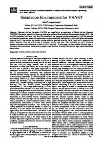
ICS, ICM
Workstations
Onboard channels
Switch
Ethernet, TCP/IP
RTES devices
Figure 1. Structure of the environment’s hardware The environment’s software runs on Debian GNU/Linux operating system. The hardware part of the environment includes following groups of components (see Fig. 1): •
instrumental computers for simulation (ICS);
•
instrumental computers for channel monitoring (ICM);
•
automated workstations for human operators;
•
hardware RTES devices;
•
hardware data exchange channels that interconnect RTES devices, ICS’s and ICM’s.
Instrumental computers and workstations are x86 PC computers connected to an Ethernet channel. ICS’s perform simulation of missing RTES devices through execution of models developed by the environment user or by supplier of the device. The deviation of modeling time from physical one is within 10 -4 sec. This accuracy is guaranteed by dedicated real-time extensions of the Linux kernel that are provided by the runtime subsystem of DYANA simulation environment [1]. ICS contains adapter cards that provide access to data exchange channels (supported standards are MIL STD1553B [3], ARINC 429; support for Fibre Channel is under development). Through these adapter cards, the models of RTES devices perform data exchange through the channels in real time, completely or in given part simulating the presence of corresponding hardware RTES devices on the channel. It is important to notice that a model can act as a MIL STD-1553B bus controller, to enable integration of a subset of RTES devices that does not include the bus controller. Support for real-time interaction between simulated RTES devices and real ones through hardware channels allows incremental RTES integration with step-by-step replacement of models with hardware devices, up to a complete integrated RTES. In this way testing and verification of can be performed with any combination of real and simulated devices. ICM’s perform monitoring of data exchange through channels and record the resulting traces to the hard disk for subsequent analysis. During the simulation, unified time is maintained on all instrumental machines, with deviation between machines limited to 10 -5 sec. A specialized protocol for precise generation of synchronous events is utilized which uses a dedicated network that connects LPT ports of the ICM’s and
ICS’s. Periodically, one of the ICM’s (the master of time synchronization) sends a signal through its LPT port and other computers receive the signal and fixate a synchronous event. Registration of all events occurring in models and of exchange through channels is performed in the unified time. This enables precise mapping of events in different models and channels to a single timeline. Workstation tools support following activities: •
simulation model development with support for model revision control;
•
defining the configuration of the environment, including distribution of models to ICS’s and settings for channel monitors;
•
control for the simulation process with support for manual change of models’ parameters by the user in runtime;
•
dynamic visualization of the simulation process, including display of models’ parameters and results of channel monitoring;
•
analysis of the simulation results, including the traced values of models’ parameters, traced events in models and in channels.
Simulation models for the environment are written in a specialized modeling language that is based on a subset of C language extended with functionality and constructs for synchronizing the model execution with real time and for performing intermodel communication.
3. RTES integration process For RTES integration, the HITL environment is used in cooperation with the tool system for scheduling of data exchange through MIL STD-1553B channels (Scheduler CAD) [4, 5] which is also developed in the CS Lab. Following components of the Scheduler CAD are essential for cooperative application of the CAD and the environment: •
•
RTES project database that keeps the data: −
on the RTES structure (set of devices and data exchange channels; topology of the onboard network);
−
on the protocols and formats of data exchange between devices (input and output data formats, structure of messages, schedules of data exchange);
tools for automatic construction of data exchange schedules for execution by MIL STD-1553B bus controller devices;
The technology of the HITL environment application to RTES integration in case of incomplete set of available RTES devices involves the following steps: 1) preparation of the environment hardware, in particular connecting instrumental computers (ICS’s, ICM’s) and RTES devices to the data exchange channels; 2) filling the RTES project database with data on the RTES structure, on protocols and formats of data exchange between devices; 3) automated generation of interface sections of the RTES device models (including input and output parameters, interfaces of models with channels, interconnections between models);
4) implementation of the functionality logic for models of the devices that are not yet available in hardware; 5) automatic construction of schedules of data exchange for MIL STD-1553B channels (by means of Scheduler CAD); 6) automatic generation of code for schedule definition: a) for hardware RTES devices that act as bus controllers; b) for models of devices; 7) automatic generation of code for message packing and unpacking: a) for hardware RTES devices; b) for models of devices; 8) defining the configuration of the environment: distribution of models to ICS’s, settings for channel monitoring and for simulation events registration; 9) performing the simulation with a given set of hardware RTES devices and device models; 10) analysis of simulation results, including automated verification of conformance of the recorded data exchange sequences to reference exchange schedules from the project database. After extending the set of RTES devices available in hardware, integration of the extended set of devices requires performing only those steps that are concerned with attaching the new devices, performing HITL simulation with these devices instead of corresponding models, and analysis of simulation results. In course of integration of subsequent versions of the RTES (e.g. during development of a RTES product line), previously developed models, database contents and environment configurations can be reused. The environment can also be applied to simulation model-based testing and validation of the application software and system software of RTES devices. To perform these activities, one has to implement models of low-level services of the device’s operating system, in particular models of interprocess communication services and of drivers that provide access to channel adapters. After implementing the models of these services, real source code of the device’s application software and (partially) system software can be included into the simulation model of the device. Performing simulation involving the real source code enables: 1) testing and validation of the device’s application and system software in absence of the hardware device; 2) performing detailed observation of selected variables of the device’s software by using the environment’s service for dynamic visualization of model’s parameters. After completion of testing the device’s software on the model, the software is loaded to the real device (in case it is already available) and checked out on the device. In case when the device is available in hardware from the beginning of RTES integration, applying the environment extends the subset of system software involved in testing, since feeding the device’s input interfaces with data through hardware channels activates the system software responsible for receiving and unpacking the data. A particular case of this approach to checking out the software on the real device involves complete simulation of the
device’s environment (i.e. feeding and reading data to/from all interfaces of the device) and analyzing the correctness of the device’s responses to test data sets generated by models and delivered to the device’s inputs through hardware channels. The HITL environment has an open architecture that enables integration with other similar environments that may be provided by other workgroups. Such integration is reasonable, for instance, when special-purpose computers are required to perform specific simulation-related tasks. Examples of such tasks are real-time generation and registration of video data streams using broadband optical channels, and obtaining control actions from the pilot through actuators in the cockpit simulator. Existing implementation of the HITL environment utilizes a specialized Ethernet-based data exchange protocol for interaction with external environments. Application of the HLA technology [6] for this purpose is considered future work.
4. Application of the environment to RTES architecture evaluation On early stages of RTES development, a problem of defining the RTES architecture arises. There RTES developer usually has to choose one of several possible RTES architectures. Since most of RTES devices are typically unavailable on early stages of RTES development, it is impossible to perform full-scale hardware test runs or even HITL simulation to evaluate different RTES architectures. To support RTES architecture evaluation, the presented simulation environment enables development and execution of a purely software model of the RTES. Runtime subsystem of the environment includes built-in models of data transfer channels so that device models can run without utilizing hardware channels and channel adapters. Real software of RTES devices can be included into the models and involved in simulation. Following problems of RTES architecture evaluation can be solved using the presented simulation environment: 1) estimation of throughput margin on data transfer channels via simulation of data exchange according to real schedules; 2) exploration of RTES resilience to interference on channels by using the channel model’s functionality to simulate exchange failures, including bit inversion, loss of messages, etc. 3) estimation of CPU load on RTES devices by combining simulation with techniques developed in the CS Lab for estimation of software task execution time depending on the task’s input data [7], and estimation of task’s worst case execution time [8]; 4) assessing the dependability of the RTES architecture via simulation-based evaluation of fault tolerance facilities of the RTES [9]. Execution of a purely software model of the RTES can be performed in a non real-time mode. If the computational complexity of the RTES model is too high, and it is necessary to run the simulation multiple times or to simulate a long interval of RTES operation, it is reasonable to simplify the model by removing components that are not essential for computation of the RTES characteristics that have to be measured. The technique developed in the CS Lab for automatic scaling of simulation models [10] supports finding and truncating the nonsignificant components of the RTES model, along with reducing the complexity of components responsible for calculation of the essential results of simulation.
5. Conclusion In this paper we present a hardware-in-the-loop simulation environment developed in the CS Lab of Computational Mathematics and Cybernetics department of the Moscow State University. The environment enables incremental integration of onboard real-time embedded systems (RTES), analysis of RTES operation, and simulation-based evaluation of RTES architecture. Simulation testbeds based on the environment are applied in industry for development of modern real-time embedded systems. Tasks for future development of the testbed include: •
implementation of support for Fibre Channel technology, including data exchange between models and real devices through optical channels;
•
involving the HLA technology for interaction with other testbeds in course of collaborative simulation;
•
integration of simulation tools with monitoring tools from the operating system of RTES devices to enable comprehensive tracking of devices’ operation.
6. References [1] A.G. Bakhmurov, A.P. Kapitonova, R.L. Smeliansky, “DYANA: An Environment for Embedded System Design and Analysis“, in Proc. of 32-nd Annual Simulation Symposium, San Diego, California, USA, April 11-15, 1999. – Р. 50-57. [2] M.P.A.M. Brouwer, et al., “Developments in Test and Verification Equipment for Spacecraft“. Technical report NLR-TP-2000-658, National Aerospace Laboratory, Netherlands, 2000. [3] U.S. Standard MIL STD-1553B “Aircraft internal time division command/response multiplex data bus”, U.S. Department of Defense, Washington D.C., 1978. [4] V.V. Balashov, V.A. Kostenko, R.L. Smeliansky, S.V. Vavinov, “A Tool System for Automatic Scheduling of Data Exchange in Real-Time Distributed Embedded Systems“, in Proc. of the 7th IEEE International Symposium on Computer Networks (ISCN'06), Istanbul, Turkey, 2006. [5] V.V. Balashov, V.A. Kostenko, R.L. Smeliansky, “A Tool System for Automatic Scheduling of Data Exchange in Real-Time Distributed Avionics Systems“, in Proc. of the 2nd EUCASS European Conference for Aerospace Sciences, Brussels, Belgium, 2007. [6] IEEE 1516 Standard “Modeling and Simulation (M&S) High Level Architecture (HLA)-Framework and Rules”, IEEE, 2000. [7] K.O. Savenkov, N.V. Youshchenko, “A Methodology for Specification of Processor Behavior for Program Execution Time Estimation”, in Proc. of the All-Russian Conference on Methods and Tools of Information Processing, Moscow, Russia, 2003, pp. 486–491 [in Russian]. [8] V.V. Prus, “A Methodology for Worst Case Execution Time Estimation for Processors with Pipelined Architecture”, in Proc. of the 2nd All-Russian Conference on Methods and Tools of Information Processing, Moscow, Russia, 2005, pp. 167–174 [in Russian]. [9] D.Yu. Volkanov, “Applying Simulation to Estimate Dependability of Distributed Computer Systems”, in Proc. of the All-Russian Conference on Methods and Tools of Information Processing, Moscow, Russia, 2003, pp. 343– 348 [in Russian]. [10] K. O. Savenkov, R. L. Smeliansky, “Scaling Down Discrete-Event Simulation Models”, Programming and Computer Software 32(6), MAIK Nauka/Interperiodica, Moscow, Russia, 2006, pp. 308-316.