Page 1 ... dedicated processor and the proposed hardware scheduler. Experimental evaluation ... scheduling algorithm implemented in software on a dedicated.
2010 23rd International Conference on VLSI Design
A Hardware Scheduler for Real Time Multiprocessor System on Chip Nikhil Gupta, Suman K. Mandal, Javier Malave, Ayan Mandal and Rabi N. Mahapatra Texas A & M University, College Station, TX 77843 {ngupta, skmandal, jmalave, ayan, rabi}@cse.tamu.edu This results in increased overhead in terms of scheduling time and context switching which in turn, translates to higher energy consumption. It is possible to reduce these overheads by replacing the replicated scheduling operations by a central scheduler unit. The central scheduler can communicate the scheduling decision to the processors upon completion of schedule calculation. Although the centralized approach is more efficient than the replicated approach, such a scheduler should be fast enough to support a large number of tasks for multiple processors without suffering from unpredictability of scheduling delays. This motivates the use of a hardware scheduler that will meet the above goals.
ABSTRACT This paper presents the design and implementation of a lowpower hardware scheduler for multiprocessor system-on-chips. The Pfair scheduling algorithm is considered with three different implementation schemes: replicated software scheduler running on each processor, single software scheduler running on a dedicated processor and the proposed hardware scheduler. Experimental evaluation with benchmarks shows that the hardware scheduler outperforms the other two schemes in terms of energy consumption by an order of magnitude of 105 and scheduling delay by an order of magnitude of 103.
Despite the optimal nature of Pfair algorithm, it can be inefficient and computationally expensive when implemented in serialized software. Pfair algorithm involves computation that grows linearly with the number of tasks to schedule. This adds to uncertainty in the effective utilization of the system if the scheduler and the tasks share resources. A parallel implementation can get rid of the unpredictability in scheduling delay and can increase effective utilization. Since scheduling is performed in a dedicated hardware module, time overhead is minimized. The parallelizable nature of Pfair can lead to a significant speed up of the scheduling process when implemented in hardware.
Categories and Subject Descriptors B.7.1 [Integrated Circuits]: Types and Design Styles – Algorithms implemented in hardware & VLSI. C.3 [Special Purpose and Application–Based System]: RealTime and Embedded Systems
General Terms Algorithms, Management, Performance, Design.
Keywords Hardware Pfair Scheduler, Multiprocessor, Low Power
In this paper, we propose a low power hardware Pfair scheduler for MPSoC. The speed-area-energy trade-offs involved in the design of a hardware Pfair scheduler were analyzed. We compare its performance in terms of scheduling delay and energy consumption with two other implementation schemes: (1) The replicated Pfair scheduling algorithm running in software on all the processors in the multiprocessor system; and (2) The Pfair scheduling algorithm implemented in software on a dedicated processor. We also report the area and energy consumption of hardware scheduler through suitable synthesis work.
1. INTRODUCTION Today, most desktops run on multiprocessor systems. The popularity of multiprocessor systems is expected to continue, and in the future, most mobile, even embedded systems will feature multiprocessors. Increasing the number of processors on a chip is the most viable method of increasing processor performance. But, along with the performance gains, multiprocessor systems also present new challenges for system designers. One of these challenges is the efficient scheduling of real-time tasks upon multiprocessor systems.
The main technical contributions of this paper are as follows:
Scheduling real time tasks in a multiprocessor environment is a challenging task. Given n processors and a periodic task set with utilization n, only a few scheduling algorithms can correctly schedule the task set. Baruah et. al. proposed Pfair scheduling algorithm which can correctly schedule a periodic task set on a multiprocessor system as long as the total utilization of the task set does not exceed the number of processors in the system [1]. This optimality condition allows one to minimize the number of processors required to schedule a given task set and makes the Pfair scheduling algorithm suitable for real time systems.
Introduced the use of a hardware Pfair scheduler in MPSoC to reduce energy consumption.
2.
Designed, implemented and evaluated the Low-power Hardware Pfair scheduling scheme suitable for multiprocessor environment.
3.
Evaluated the performance of the Low-power Hardware Pfair scheduler using real-time benchmarks in terms of scheduling delay and energy consumption.
The rest of this paper is organized as follows: Section 2 discusses related work. In section 3 we describe our system model. Section 4 discusses the Pfair scheduling algorithm. Section 5 describes our hardware implementation of the Pfair scheduling algorithm. Results and discussions are presented in section 6. Finally, section 7 concludes the paper.
Traditionally, scheduling in multiprocessor system has been implemented in an inefficient fashion. Each processor in the system runs a copy of the scheduling algorithm in software to decide on the next task to run. Running multiple scheduler copies is inefficient use of resources in multiprocessor systems like MPSoC. The inefficiency is further aggravated when either the number of tasks or the number of processors in the system is high. 1063-9667/10 $26.00 © 2010 IEEE DOI 10.1109/VLSI.Design.2010.43
1.
264
2. RELATED WORK
optimally schedule periodic tasks on multiple processors. Following is an overview of the Pfair scheduling algorithm.
While the concept of implementing run time schedulers in software is not new, to the best of our knowledge, this is the first implementation of a hardware scheduler for the Pfair scheduling algorithm.
4.1 Overview In a Pfair scheduled system, processor time is allocated to tasks in discrete units of time; the unit time interval [t; t + 1) is called the slot t. During each slot a given processor runs only one task. Pfair scheduling ensures that the rate of progress of a task does not deviate too much from its ideal rate of progress which is equal to its weight w. The deviation, known as lag, is formally defined as:
There have been similar works in the literature which implement a part or whole of the runtime scheduler in hardware to improve predictability and the ability to meet real time constraints [11, 12, 13, 14, 15]. Mooney et. al. developed a tool for run time scheduler systhesis from a system specification [11]. Recently, Kumar et. al. proposed and approach to accelerate dynamic task scheduling on multiprocessor systems [12]. Their design accelerates task queues in hardware to overcome the deficiencies of software queues and achieve better load balancing.
lag(t) = w*t – allocated(t),
(1)
Where lag(t) and allocated(t) denote the lag of the task at time t and the number of slots allocated to the task till the time t. A schedule is said to be Pfair if and only if the following conditions holds at all times for all tasks:
Hildebrandt and Timmermann developed a scheduling coprocessor for uniprocessor real time systems [5]. The coprocessor was aimed at speeding up the scheduling task of a RTOS by parallelizing the task prioritization in hardware. They present results on the synthesis of the co-processor module and did not consider benchmarks for evaluation of scheduling performance. Our design achieves similar synthesis results but in a multiprocessor environment.
-1 < lag(t) < 1
(2)
The characteristic symbol (a +, 0 or -) for a task at time t is defined as follows:
Danne et. al. proposed a hardware scheduler design for programmable devices [4]. They implemented a scheduler that performs the MSDL scheduling for real time tasks. They reported a linear scheduling time with the increased number of tasks and processors. The motivation was similar to our design; i.e. reducing overall scheduling overhead. Since the scheduling algorithm was different and the hardware design varies significantly from ours, we do not compare our results with theirs.
α(t) = sign (w*(t+1) – floor(w*t ) -1)
(3)
A task is said to be urgent if its lag is positive and characteristic symbol is not a -. Similarly, a task is said to tnegru (opposite of urgent) if its lag is negative and characteristic symbol is not a +. Otherwise the task is said to contending.
its be its be
The characteristic substring of a task at time t is defined as the concatenation of its characteristic symbols at times t, t+1, t+2 and so on, till a 0 is reached. A partial order on the contending set is defined by ordering each task according to the lexicographic ordering of its characteristic substring. The lexicographic ordering of substrings follows + > 0 > -.
Anderson et. al. discussed the implementation of Pfair scheduling in hardware in the context of network processor design [6]. However, they did not describe a detail implementation due to several applicability issues of Pfair in network processor design context.
During each slot, the Pfair algorithm performs the following operations: 1. Calculate lag and alpha of each task for the current time slot. 2. Partition the taskset into urgent, tnegru and contending subsets.
3. SYSTEM MODEL
3. Compute the characteristic substring for each contending task and define the partial order on the contending set.
In this section we discuss the tasks and energy model that we use.
3.1 Task Model
4. Schedule each task from the urgent set on a different processor. For the remaining processors, select the greatest (based on the partial ordering) tasks from the contending set and schedule them.
We consider periodic real time independent tasks with known periods and worst case execution times. Each invocation of a task is called a job and considered to have a deadline at the end of the period. Formally we denote a task as τ = {e,p} where e is the worst case execution time and p is the period of the task. The weight of a task is represented by: w = e / p. In this work we focus on static task set which is reasonable for typical MPSoC applications.
4.2 Scheduler Implementation Schemes 4.2.1 Replicated Software Scheduler This is the most commonly used multiprocessor scheduling scheme. In this technique, the scheduling algorithm runs on every processor at the end of an execution slot and selects the corresponding tasks for execution in the next slot. The process involves a compulsory context switch and the runtime of the scheduling algorithm and possibly a task migration when the running task resumes on a different processor. The scenario, illustrated in Figure1(C), leads to a high degree of scheduling overhead.
3.2 Energy Model For studying this problem, we assume the MPSoC consists of StrongARM processors (SA1100) and other hardware IP blocks. The scheduler runs on SA1100 processors when it runs in software. Thus we use the Intel SA1100 processor energy model to compute the energy consumption of the scheduling algorithm for when it runs in software.
4.2.2 Software Scheduler on a Dedicated Processor Another method of implementing a multiprocessor scheduling algorithm is to run the scheduler on an independent on-chip processor which communicates with the other processors and notifies them with the scheduling details prior to the next execution slot [Illustrated in Figure 1(B)]. In this case, the
4. PFAIR SCHEDULING Baruah et. al. presented the notion of proportionate progress in the context of multi processor periodic scheduling problem [1].Their proposed scheduling algorithm, known as Pfair has been shown to
265
scheduling time is not spent in the processors themselves and hence the scheduling overhead is reduced. This scheduling method is simple to implement since the already designed scheduler software can run on a separate processor and does not require many design changes. However, this technique requires an extra processor and hence is costly in terms of area and power
time. The steps involve maintaining the data structures for each task which include information about the task and current slot number. Primary computations are calculation of lag, characteristic symbol and characteristic string. The original scheme of computation involves floating point multiplication for updating task lag and characteristic string. We have modified the definitions to make the computation incremental so that the only additions and comparisons are used. This was done by multiplying all the task parameters with the corresponding task’s period, since all fractional values are result of division by period of the task. This eliminates the floating point computation required by the original Pfair scheme and simplifies the mathematics to a great deal. Also, as required by computation of α, floor(w*t) can be maintained in its integral equivalent after multiplication by period The modified definitions are as follows: For a given task: Period = p*p
(4)
Execution Time = e*p
(5)
Weight = e/p*p = e
(6)
S(t) = e, if a task is scheduled, 0 otherwise
(7)
lag(t) = lag(t-1) + e – St-1
(8)
Ideal(t) = Ideal(t-1)+e for t>0, 0 for t =0 FIdeal(t) = 0 if t = 0
(9) (10)
= Fideal(t-1)+p, if Ideal(t-1)+e >= Fideal(t-1)+p =Fideal(t-1), otherwise alpha is the characteristic string at time t where alpha(t) = sign(Ideal(t+1) – Fideal(t) – p)
(11)
In the above definitions, S(t) denotes whether or not the task has been scheduler in slot t. Ideal(t) is equivalent to w*t and Fideal(t) is equivalent to floor(w*t). The definition of the sets urgent, tnegru and contending remain the same. The original Pfair algorithm can be found in [1] and has been kept unchanged. The significant change that had to be done was the evaluation partial order of characteristic string in parallel. In the following subsections, we discuss the scheduler design in detail.
5.1 System Architecture
Figure 1: Overview of the Three Different Implementation Options along with the differences
The steps of the Pfair scheduling algorithm are clearly reflected in the hardware design. The scheduler consists of the following main blocks: 1. Task State Registers (TR) along with logic to update the attributes lag and ideal. 2. Partial Order Calculator (POC), 3. Schedule Generator (SG) and 4. Master Controller (MC). The overall organization of the hardware Pfair scheduler is illustrated in Figure 2. The details of each component are discussed in the following sections.
consumption.
4.2.3 Pfair Scheduler Core The third option is an on chip dedicated hardware core running the scheduling algorithm. The hardware core works in a similar way as the dedicated software scheduler, but it has a faster response time and requires much lesser energy during operation. The nature of the Pfair scheduling algorithm offers many parallelization options for fast scheduling. Like dedicated software scheduling, this technique is free from the scheduling delay overhead. The area requirement of a dedicated scheduler core is also expected to be much less compared to a general purpose processor core.
5. HARDWARE PFAIR SCHEDULER The original Pfair algorithm does not yield itself to a straight forward hardware implementation. Pfair works by calculating the proportionate progress of a task from its period and execution
Figure 2: Pfair Scheduler Block Schematic
266
5.2 Task State Registers (TR)
looking at a mask which is calculated based on the number of ‘+’ symbols, ‘0’ symbols and ‘-’ symbols as in Figure 4. In the figure the arrows show the relative position of the number of tasks to be selected and the corresponding mask values. Mask values of 1, 3 and 5 represent completion of the partial order calculation process. For mask values 0 (resp. 2) tasks with characteristic symbol 0, - (resp. -), do not need to be further evaluated. This technique is easily implemented in hardware and greatly simplifies the evaluation. The mask value is the output of this module and is used by the schedule generator.
This is the main data structure block in the design. It comprises of a persistent register for each task in the system. The fields in the register are shown in Figure 3. As our modified definitions are incremental, we only need to maintain the current values of task parameters. The fields are updated at the beginning of each slot using the incremental formulae (8-11) described earlier.
5.4 Schedule Generator (SG) This module sets the schedule bits for the tasks that are selected based on the partial order. It does so by interpreting the scheduling mask generated by the partial order evaluator at the end of each pass. When all the tasks are scheduled from the contending set or all the processors are allocated a task, the process completes for that slot. The schedule generator notifies the master controller on completion of schedule generation and master controller stores the generated schedule and presents them to the processor interrupt service routine (ISR) as requested.
Figure 3: Fields in a Task Register Along with the registers, this block also contains the logic that performs the computation required to update these fields at the beginning of each slot. The update logic is simple and the details are omitted due to limited space. This block can compute the urgent, tnegru and the contending sets at the beginning of each slot. The next module does the partial ordering of the contending set by looking at the contending bits in the task registers. Num +
0
Num 0
1
2
5.5 Master Controller (MC) The heart of the master controller is essentially a state machine described in Figure 5. In addition to the scheduling state machines, it also implements the interfacing logic to the processors. The master controller is woken up using a timer at the beginning of each slot and it performs the scheduling task for next k slots and stores the generated schedule. Upon timer expiration, it checks if the schedule is already computed. If schedule details are available it immediately interrupts the processors that need to do a context switch. Otherwise, it runs the scheduler to compute the schedule for the next k slots. The master controller also provides an interface to program the task set at the time of system startup.
Num -
3
4
5
Figure 4: Partial Order Evaluator
5.3 Partial Order Calculator (POC) This module calculates the partial order needed to select tasks from the contending set. The partial ordering is defined over the characteristic string of each task in the contending set. This module, incrementally calculates the characteristic string of the relevant tasks as the calculation of partial order progresses. We optimize this process by computing the characteristic string depending on the number of tasks to be selected from the contending set. At each stage of the incremental process, we disable tasks from being considered in subsequent iterations by
5.6 Scheduler Operation The scheduler is invoked by a timer. The timer can be programmed during the system startup to fire with a period same as the slot duration. The scheduler first checks whether the scheduling decision for that slot is already present or not. If not, it calculates the schedule. Next, it checks which processors need to be interrupted for a task switch. It then sends interrupt signals to those processors to invoke the context switch ISR. At this point the ISRs query the scheduler core using some addressing scheme for the next task to run. This process can be completed in one memory access. The ISR can immediately switch to the next task to run it. The scheduler core only needs to respond to the queries from the ISRs once it has sent the interrupts. So it goes to idle mode after sending the interrupt signals to save energy.
6. EVALUATION In this section we will compare the performance and predictability of our hardware Pfair scheduler with that of the other two implementation schemes.
6.1 Experimental Setup 6.1.1 System Setup To obtain time and power estimates of the software version, the scheduling algorithm was implemented in C and was run on an ARM power performance simulator based on SimpleScalar [7][9]. The ARM simulator can perform a low level power performance simulation of an ARM binary running on an Intel SA1100 processor. For the hardware Pfair scheduler, Synopsys design
Figure 5: FSM of the scheduler Core
267
compiler was used for synthesis power, area and timing results. We use the H.263 benchmark from the DSPstone suite. All the three different implementation options were evaluated. The results of the simulations are reported in Section 6.2.
terms of the number of cycles required to schedule a slot. This is followed by synthesis results of the Pfair scheduler core.
6.2.1 Comparison of Different Schemes First we discuss the results on the scheduling delay. The scheduling delay for the replicated, and dedicated software scheduler were found out using the Simplescalar simulator [7]. We have used the Synopsys VCS simulator to measure the scheduling delay of the Pfair scheduler core. Figure 6 shows the scheduling delay due to the three different implementation schemes. The replicated and the dedicated software schemes yield the same scheduling delay. But the Pfair scheduler core shows an order of magnitude improvement (103) in scheduling delay. For example, in the case of taskset having 30 tasks, which uses 14 processors, the software schemes completes the scheduling operation for one slot in 185937 cycles whereas the hardware scheme completes the same in 142 cycles. In real time applications that have tasks with very small periods, the scheduling decisions need to be made much quickly compared to the periods of the task set. Hence, the Pfair scheduler core should be the preferred choice for such systems.
6.1.2 Benchmarks The benchmark selected was H.263 from DSPstone suite [8]. H.263 is a video codec standard originally designed as a lowbitrate compressed format for video conferencing. This requires soft real time processing. We dissociated a portion of this application into the following subtasks: DCT, Dequantization, IDCT, Quantization and calculation of SAD (sum of absolute division). All these were applied on an 8x8 macroblock in a pipelined fashion. By partitioning H.263, we get the execution time and period for each of the individual subtasks. Each subtask was cross-compiled for the ARM architecture (StrongARM) and simulated with SimpleScalar. The periods were obtained by assuming different frame rates used in real applications as in Table 1. We assume an image resolution of 480x240 resulting in 300 macroblocks per frame. Table 1 lists all the details of the benchmark that we have used. Four taskset configurations were generated with utilizations varying from 5 to 17. We used the minimum possible number of processors to schedule each taskset.
1E+06
Frame rate
Utilization
1
5
2
Cycles per slot
Taskset Number
Replicated
1E+05
Table 1 : Benchmark details
1E+04
Number of tasks
Number of processors
5.25
10
6
12
11.15
25
12
3
15
13.25
30
14
1E+01
4
24
16.57
50
17
1E+00
Dedicated software scheduler
1E+03 1E+02
Pfair scheduler core 10
25
6.1.3 Evaluation Criteria
30
50
Number of tasks
We have evaluated the scheduler core design in terms of speed, area and power. We define each property as follows:
Figure 6: Scheduling Delay
Speed: We measured the number of cycles taken by the scheduler to perform the scheduling task. We also considered the length of the ISR running in the processors while calculating the overall scheduling time. We then use the scheduler frequency to calculate the absolute time required to schedule the tasks.
Energy per 106 slots (micro joules)
1E+10
Area: The scheduler core was synthesized using 90 nm process technology from Synopsys [10]. Synopsys design compiler was used to obtain area estimates using the library. We compared the area of the scheduler core to that of an additional ARM core which can be used in the dedicated software scheduler. Power: The primary motivation of the scheduler core design being low power, this is the most important metric in our evaluation. We estimate the static and dynamic power consumption in the scheduler core using Synopsys Power Compiler. We compare the power and energy estimates to those of replicated scheduler scheme and dedicated software scheduling scheme. Although instantaneous power of our scheduler core can be higher than the software schedulers, the overall energy consumption is much lower. The corresponding results have been illustrated in section 6.2.2.
Replicated
1E+08 1E+06
Dedicated software scheduler
1E+04
Pfair scheduler core
1E+02 1E+00 10
25
30
50
Number of tasks Figure 7: Energy Consumption The energy consumption of the Pfair scheduler core is compared to the dedicated software and replicated implementation schemes in Figure 7. To calculate energy consumption of the Pfair scheduler core, we used the power values from the synthesis results. The scheduling delay per slot was obtained using Synopsys VCS simulation. For the dedicated software and replicated implementations, an ARM power performance simulator based on the SimpleScalar was used [9]. The dedicated
6.2 Results In this section we discuss the results on scheduling delay and energy consumption obtained by running real-time benchmark on the three implementations. The scheduling speed is compared in 268
Pfair scheduler yields an order of magnitude (105) improvement over both the schemes. For example, in the case of task set having 30 tasks that uses 14 processors, the replicated scheme consumes 508 micro joules whereas the hardware scheme consumes only 15 nano joules. The low scheduling delay and the low energy consumption of the Pfair scheduler core make it an attractive choice for use in a low power multiprocessor system on chip.
order improvement in scheduling delay while consuming 105 orders less energy. Future work includes incorporating low power techniques such as dynamic voltage/frequency scaling to further increase the efficiency of the system.
REFERENCES [1] S. K. Baruah, N. K. Cohen, C. G. Plaxton, and D. A. Varvel, Proportionate progress: a notion of fairness in resource allocation, In Proceedings of the Twenty-Fifth Annual ACM Symposium on theory of Computing, 1993, pp-345-354
6.2.2 Pfair Scheduler Core Synthesis Results
Gate Count x 10000
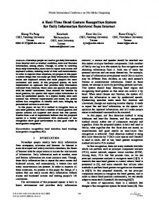
We have synthesized the design using TSMC 90nm process technology. As discussed in the Section 5, the area and power consumption depend on the number of tasks supported. We have synthesized designs to support task sets with 10 to 50 tasks. Figures 7 and 8 show these synthesis results. As expected, the power and area consumption of the design increases with the number of tasks. This is due to the linear increase in the number of state registers as the number of tasks increases. This replication maintains the scheduling delay as the number of tasks increases (Figure 6). 14 12
[2] ARM7TDMI Data Sheet, http://www.eecs.umich.edu/~panalyzer/pdfs/ARM_doc.pdf [3] V. Mooney and D. Blough, “A hardware-software real-time operating system framework for SoCs”, Design & Test of Computers, IEEE, vol. 19, 2002, pp. 44-51 [4] K. Danne, R. Miihlenbernd, M. Platzner, "Executing Hardware Tasks on Dynamically Reconfigurable Devices Under Real-Time Conditions", In Proceedings of the International Conference on Field Programmable Logic and Applications, 2006. pp.1-6
Gate Count
[5] J. Hildebrandt, D. Timmermann, “An FPGA Based Scheduling Coprocessor for Dynamic Priority Scheduling in Hard Real-Time Systems”, In Proceedings of International Conference on Field Programmable Logic and Applications, 2000, pp. 777-780
10 8 6 4 2 0 0
10
20 30 40 Number of Tasks
50
[6] A. Srinivasan, P. Holman, J. Anderson, S. Baruah, and J. Kaur, " Multiprocessor Scheduling in Processor-based Router Platforms: Issues and Ideas ", In Network Processor Design: Issues and Practices Volume II, P. Crowley and H. Hadimioglu (eds.), 2004, pp. 75-99.
60
Figure 8: Synthesis Gate Count
[7] SimpleScalar Performance Simulator, www.simplescalar.com
Total Power (micro watts)
The total power consumption of the hardware design is shown in Figure 9. We used Synopsys design compiler to get the Dynamic and leakage power of the circuit. The total power consumption is in microwatts, which is an order of magnitude (103) lesser than the power consumption in dedicated software schedulers. 1800 1600 1400 1200 1000 800 600 400 200 0
[8] V. zivojnovi'c, J. M. Velarde, C. Schläger, and H. Meyr, "DSPSTONE: A DSP-oriented benchmarking methodology," In Proceedings of the International Conference on Signal Processing and Technology, 1994. [9] Sim-Panalyzer: The SimpleScalar ARM Power Modelling Project, http://www.eecs.umich.edu/~panalyzer/
Total Power
[10] Synopsys VCS Simulator. http://www.synopsys.com [11] V. Mooney, T. Sakamoto, G. De Micheli, "Run-time scheduler synthesis for hardware-software systems and application to robot control design", In Proceedings of the Fifth International Workshop on Hardware/Software Codesign, 1997, pp.95-99.
0
10
20
30 40 Number of Tasks
50
[12] S. Kumar, C. J. Hughes, A. Nguyen, “Carbon: architectural support for fine-grained parallelism on chip multiprocessors”, In Proceedings of the 34th Annual international Symposium on Computer Architecture, 2007. pp. 162-173.
60
Figure 9: Synthesis Total power.
[14] A.C. Nácul, F. Regazzoni, and M. Lajolo, “Hardware scheduling support in SMP architectures”, In Proceedings of the conference on Design, automation and test in Europe, 2007, pp. 642-647.
7. CONCLUSION The imminent requirements of high performance embedded systems will require multi core embedded design to be in place. Scheduling real time tasks on such platform has to be efficient and optimal to obtain maximum performance. The proposed energy efficient hardware scheduler core can provide such performance at a reduced energy cost. Experimental evaluation has shown a 103
[15] T. Nakano, A. Utama, M. Itabashi, A. Shiomi, and M. Imai, “Hardware implementation of a real-time operating system”, In Proceedings of the 12th TRON Project International Symposium, 1995, pp. 34-42.
269