automated quantum circuit synthesis is still only at the beginning of its exploration ... technologies that exist already in practice. Each of these .... similar to technology mapping and physical design areas in classical CAD, but so far they are ..... Symposium on Theory of Computing (STOC), 1998. 12. .... VLSI Design," Vol.
A Hierarchical Approach to Computer-Aided Design of Quantum Circuits Marek Perkowski,+* Martin Lukac,* Mikhail Pivtoraiko,* Pawel Kerntopf, & Michele Folgheraiter *, Dongsoo Lee, + Hyungock Kim,+ Woong Hwangbo, Jung-wook Kim+ and Yong Woo Choi.+ *Department of Electrical and Computer Engineering, Portland State University, Portland, OR, 97201. USA, +Department of Electrical Engineering, Korea Advanced Institute of Science and Technology, 373-1, Kusong-dong, Yusong-gu, Taejeon, 305-701, Korea, & Institute of Computer Science, Warsaw University of Technology, Nowowiejska 15/19, 00-665 Warsaw, Poland.
Abstract: A new approach to synthesis of permutation class of quantum logic circuits has been proposed in this paper. This approach produces better results than the previous approaches based on classical reversible logic and can be easier tuned to any particular quantum technology such as nuclear magnetic resonance (NMR). First we synthesize a library of permutation (pseudobinary) gates using a Computer-Aided-Design approach that links evolutionary and combinatorics approaches with human experience and creativity. Next the circuit is designed using these gates and standard 1*1 and 2*2 quantum gates and finally the optimizing tautological transforms are applied to the circuit, producing a sequence of quantum operations practically realizable. These hierarchical stages can be compared to standard gate library design, generic logic synthesis and technology mapping stages of classical CAD systems, respectively. We use an informed genetic algorithm to evolve arbitrary quantum circuit specified by a (target) unitary matrix, specific encoding that reduces the time of calculating the resultant unitary matrices of chromosomes, and an evolutionary algorithm specialized to permutation circuits specified by truth tables. We outline interactive CAD approach in which the designer is a part of feedback loop in evolutionary program and the search is not for circuits of known specifications, but for any gates with high processing power and small cost for given constraints. In contrast to previous approaches, our methodology allows synthesis of both: small quantum circuits of arbitrary type (gates), and permutation class circuits that are well realizable in particular technology. 1. Introduction While quantum mechanics and quantum computing are established research areas, automated quantum circuit synthesis is still only at the beginning of its exploration
[2,4,6,7,8]. In quantum computation we use quantum bits (qubits) instead of classical binary bits to represent information. This gives the advantage of being able to perform massively parallel computations in one time step. The design of quantum circuits of practical size is still technologically impossible (the maximum number of qubits in year 2002 is 7), but the progress is fast and there are no arguments based on physics against the possibility of building powerful quantum computers in the future. Therefore quantum computing area of research is recently flourishing. Finding an effective and efficient method of designing quantum circuits can have three application areas: (1) Optimizing quantum circuits for NMR [25,26,27,28,29], ion trap, quantum dot, cavity quantum electrodynamics or Si-based nuclear spin quantum computer technologies that exist already in practice. Each of these technologies has different minimization requirements and all of them require minimizing both the width and the length of scratchpad register (number of qubits processed). Width is absolutely critical and length is also important because of decoherence. Circuit reduction is very important for present technology, so exact or sub-minimal methods should be developed for small circuits, less than 7 variables. This is a very small number from the standard CAD algorithms point of view, but the synthesis problem for quantum logic is more difficult. (2) Modeling quantum computers in FPGA-based reconfigurable hardware for speeding-up computations that are very inefficient on standard computers [9]. Since for current FPGA technologies only small quantum circuits can be emulated, the requirements are similar to point (1) (3) Designing new optimized gates and circuits for theoretical investigations and for use in future quantum computers. If we believe that such computers will exist, efficient CAD methods for large number of variables, tens or hundreds, should be developed, but these algorithms will be non-optimal. This is a theoretical research for non-existing technology in year 2002. 2. Quantum Computing The major difference between quantum logic and binary logic is the concept of the information itself. While the classical (binary or multi-valued) representations of information are precise and deterministic, in Quantum Computing (QC) the concept of bit is replaced by the qubit. Unlike classical bits that are realized as electrical voltages or currents present on a wire, quantum logic operations manipulate qubits [7]. Qubits are microscopic entities such as a photon or atomic spin. Boolean quantities of 0 and 1 are represented by a pair of distinguishable different states of a qubit. These states can be a photon’s horizontal or vertical polarization denoted by |�> or |�>, or an elementary particle’s spin denoted by |�> or |�> for spin up and spin down, respectively. After encoding these distinguishable quantities into Boolean constants, a common notation for qubit states is |0> and |1>. Qubits exist in a linear superposition of states, and are characterized by a wavefunction ψ. As an example, it is possible to have light polarizations other than purely horizontal or vertical, such as slant 45° corresponding to the linear superposition of ψ=½[√2|0>+√2|1>]. In general, the notation for this superposition is α|0>+β|1>. These intermediate states cannot be distinguished, rather a measurement will yield that the qubit is in one of the basis states, |0> or |1>. The probability that a
measurement of a qubit yields state |0> is |α|2, and the probability is |β|2 for state |1>. The absolute values are required since, in general, α and β are complex quantities. Pairs of qubits are capable of representing four distinct Boolean states, |00>, |01>, |10> and |11>, as well as all possible superpositions of the states. This property is known as “entanglement”, and may be mathematically described using the Kronecker product (tensor product) operation ⊗ [7]. As an example, consider two qubits with ψ1=α1|0>+β1|1> and ψ2=α2|0>+β2|1>. When the two qubits are considered to represent a state, that state ψ12 is the superposition of all possible combinations of the original qubits, where ψ12= ψ1⊗ψ2 = α1α2|00> + α1β2|01> + α2β1|10> + β1β2|11>. Superposition property allows qubit states to grow much faster in dimension than classical bits. In a classical system, n bits represents 2n distinct states, whereas n qubits corresponds to a superposition of 2n states. Observe also that in the above formula some coefficient can cancel, so there exist a constraint bounding the possible states in which the system can exist. These all contribute to difficulties in understanding the concepts of quantum computing and creating efficient analysis, simulation, verification and synthesis algorithms for QC. Generally, however, we believe that much can be learned from the history of Electronic Computer Aided Design and the lessons learned should be used to design efficient CAD tools for quantum computing. In terms of logic operations, anything that changes a vector of qubit states can be considered as an operator. These phenomena can be modeled using the analogy of a “quantum circuit”. In a quantum circuit wires do not carry Boolean constants, but correspond to pairs of complex values, α and β. Quantum logic gates of this circuit map the complex values on their inputs to complex values on their outputs. Operation of quantum gates is described by matrix operations. Any quantum circuit is a composition of parallel and serial connections of blocks, from small to large. Serial connection of blocks corresponds to multiplication of their (unitary) matrices. Parallel connection corresponds to Kronecker multiplication of their matrices. So, theoretically, the analysis, simulation and verification are easy and can be based on matrix methods. Practically they are tough because of the problem dimension exponential growth of matrices. Synthesis problem can be formulated as decomposing hierarchically a given unitary matrix to serial and parallel connections of smaller matrices, until basic directly realizable quantum primitives are reached. This problem is very difficult in such basic formulation and therefore several special methods have been and are being developed, especially in the last 5 years. Probabilistic calculations based on this representation are used in only very small quantum computers so far (most with 3 bits), but it was verified that information can be represented as a superposition of states of single qubits, and that in one time step operations can be performed on several qubits. Beside this useful effect of quantum computing, various other effects resulting from qubit encoding emerge, such as qubit entanglement. Moreover it was shown [7] that any quantum computing has to be reversible, which affects all synthesis methods. Concluding, building quantum computers becomes more and more technical rather than only scientific issue, and the methods developed to design them, such as formal representation, modeling and synthesis will have applications not only to quantum computing but also to DNA and other nano-technologies because of their reversible nature.
(1)
In this paper we focus only on the synthesis of arbitrary quantum circuits (and quantum gates in particular) of small size, less than five variables. We concentrate on designing the circuits from a class of permutation gates which have unitary matrices being permutation matrices. Such circuits correspond to classical Boolean functions. However, our gate design methods are for general quantum circuits, with arbitrary unitary matrices. The presented methods can be specialized to some classes such as fcontrolled-phase-shift gate circuits [25], and generalized to multiple-valued quantum logic [30,41] and mixed multiple-valued logic. The paper is organized as follows. First, we discuss some important issues related to quantum logic circuits. By discussing them we want to prove that it is not true that current binary reversible logic synthesis methods can be directly applied to permutation quantum circuits. (This is a common belief, partially true, but only a first step). By presenting this discussion, we would like to encourage researchers with logic synthesis background to create new improved methods that will be more practically useful to optimizing sequences for current existing technologies such as NMR. Our theses in the first part are the following: 1. Toffoli (CCNOT) and Fredkin are not always the best gates for quantum computing. (Toffoli gate is described by equations P=a,Q=b, R= ab ⊕ c, Fredkin gate by equations P=a, Q= a’b+ac, R=ab+a’c). Multi-input Toffoli gate look simple in a diagram, but take a lot of gates when redrawn to 3*3 gates with auxiliary constants - they are not primitives. The synthesis should be performed at one hand on a lower level of quantum primitives such as CNOT (Feynman), controlled square-root-of-not and Hadamard, and on the other hand on the level of more powerful reversible gates, such as those introduced in [17,35], to simplify the search by increasing gate granularity. 2. The transformation from optimal reversible circuit (on any level of gates) to the minimal quantum sequence for NMR programming is far from being trivial, and so far no combinatorial optimization algorithms have been created for them. The problems of gate ordering, input variable ordering, local transformations, removal of swap gates (planarization) and others, are quite similar to technology mapping and physical design areas in classical CAD, but so far they are solved only ad hoc by physicists [43]. 3. All gate cost assumptions that can be found in general quantum papers (and not in specialized papers about NMR technology) are far too approximate and can lead to highly non-optimal sequences. Second, after presenting these difficulties in more detail, we outline our CAD tools, in which evolutionary and human-oriented interactive methods are combined. We propose a generalized approach to the problem of quantum computing (QC) CAD by using a simple encoding and a generic genetic algorithm (GA) without any problemspecific operators. Our results show that, in contrast to published work [4,6], any kind of genetic operators can be used. We were able to synthesize completely automatically more complex circuits than those by previous programs, for instance the Toffoli and Margolus gates. 3. New Gates and their Cost Functions for the Optimization Algorithms
Figure 1 a b c
To
a
a
a
b
b
b
ab⊕c
c
V
V
V+
ab⊕c
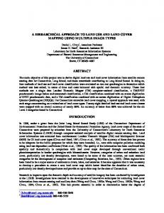
An important problem, not discussed so far by other authors, is the selection of the cost functions to evaluate the quantum circuit designs. Although the detailed costs depend on any particular realization technology of quantum logic, so that the cost relations between for instance Fredkin and Toffoli gates can differ in NMR and ion trap realizations, the assumptions used in several previous papers; that each gate costs the same, or that the cost of a gate is proportional to the number of inputs/outputs, are both far too approximate. In this paper we will illustrate more precise cost functions for gates that are used in our optimization algorithms (even more accurate costs will be presented in the forthcoming paper, here we just want to signalize the important problem). We will follow in the footsteps of previous papers in quantum computing [12,15,25-29] and we will realize all gates from 1* 1 and 2*2 gates. Moreover, according to [15] we will assume that the cost of every 2*2 gate is the same. We will assume also that a 1*1 gate costs nothing, since it can be always included to arbitrary 2*2 gate that precedes or follows it. Thus, in first approximation, every permutation quantum gate will be build from 1*1 and 2*2 quantum primitives and its cost calculated as a total sum of 2*2 gates used. Using the well-known realization of Toffoli gate with truly quantum 2*2 primitives, shown in Figure 1 [15], the cost of Toffoli gate is 5 2*2 gates, or simply, 5. In Figure 1, V is a square-root-of-NOT gate (unitary matrix V) and V+ is its hermitian. Thus V V creates a unitary matrix of NOT gate and V V+ = I (an identity matrix, describing just a quantum wire). The reader can analyze correctness of this construction by analyzing all possible values of inputs signals. (the generalization of this gate to ninputs without constant wires is shown in [12]). Now we will realize the Fredkin gate from the Toffoli gate. Using GA [16] or synthesis methods from this paper, we can synthesize the Fredkin gate using two Feynman and one Toffoli gate as in Figure 2.
Figure 2 b⊕c ⊕ ab⊕a’c = ac⊕ba’
a b
b⊕c
c
. . To
a
a b
. .
c c⊕a(b⊕c) = c⊕ab⊕ac = ca’⊕ac
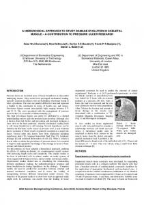
Substituting the Toffoli design from Figure 1 to Figure 2 we obtain the circuit from Figure 3a. After using the obvious EXOR-based transformation shown in the right (change of order of Feynman gates), the final circuit from Figure 3b is obtained. Observe that a cascade of two 2*2 gates is another 2*2 gate, so following [15] we obtain a circuit from Figure 3b with the cost of 5. (Each sequence in dotted lines has a cost of 1). Thus, the cost of Toffoli gate is exactly the same as the cost of Fredkin gate, and not half of it, as some authors assumed and as may be suggested by classical binary schemata of such gates, where the Toffoli gate includes a single Davio gate, while the Fredkin gate includes two multiplexers. Encouraged with this observation, let us calculate costs of other known gates. It was shown in [31] that the cost of Miller’s Gate is 7 and not 9, as might be expected from its binary schematics using Feynman and Toffoli gates. Interestingly, another realization of Miller’s gate has an even smaller cost of 6. Observe that since swap gate can be realized by a cascade of three Feynman gates, according to the cost evaluation method from [15] its cost is also 1 and not 3 as assumed previously. Similarly the costs of 3*3 gates by Kerntopf [24,34,37], Margolus [21], De Vos [24], Khan [20], and Maslow [21,22], costs of all 4*4 Perkowski’s gates [17], and other gates from [24] can be calculated. Next observe that a new permutation quantum gate with equations: P=a Q=a⊕b R = ab ⊕ c can be realized with cost 4. It is just like a Toffoli gate from Figure 1 but without the last Feynman gate from right. This is the cheapest quantum realization known to us of a complete (universal) permutation gate and it is thus worthy further
investigations. We found that the equation of this gate was known to Peres [21], but it has been not used in reversible or quantum computing. Observe that algorithms from [33,40], when given the equation of Peres gate, would return the solution composed fro Toffoli and Feynman gates, which would lead to clearly non-minimal quantum sequence. However, if the postprocessing stage of macrogeneration and next equivalence simplifying transformations were applied to results from [33,40], the minimum solution would be found. It is now a challenge to other researchers to find a cheaper universal 3*3 gate, that would use only 2*2 and 1*1 gates (it is known that several such universal sets of gates exist. [12]).
Figure 3
a
a)
b c
V
V
V+
V
V
V+
a
b)
b c
Figure 4
a
a
b
a⊕b
c
V
Cost = four 2*2 quantum gates
V+
ab⊕c
a
a
a⊕b
b c
V
V
V
V+
ab⊕c
a⊕b ⊕ ab⊕c = (a+b) ⊕c
C=0 ==> (a*b)
C=0 ==> (a+b)
Observe in Figure 4, that the Peres Gate with Feynman gates located in all possible pairs of terminals at its periphery creates powerful and inexpensive new gates. For instance by locating Feynman gate with EXOR up on output wires b and c, generates a gate with equations: a = a, b = (a+b) ⊕ c, c = ab ⊕ c. Again, the Feynman gate can be combined with the V+ gate so the cost of the combined new gate is again only four. Another possibility of connecting Feynman gate to the outputs b, c of the Peres gate is shown in Figure 5. There exist also two possibilities of connecting Feynman gate to inputs b, c, which similarly lead to two new gates, and four possibilities of connecting Feynman gates to both inputs b, c and outputs b, c, which leads to four new gates. Several other new gates can be created for another input/output terminal pairs in Figure 4.
Figure 5
a
a)
a
a⊕b
b c
V
Cost = four 2*2 quantum gates
V+
ab⊕c
a
a
a⊕b
b c
V
V
V
V+
ab⊕c
a⊕b ⊕ ab⊕c = (a+b) ⊕c C=0 ==> (a+b)
C=1 ==> (a+b)’=a’b’
4. Frame-based search generator and genetic algorithms Let us observe that there exist very many combinatorial possibilities of connecting Feynman (and other) gates to inputs and outputs of basic gates, as was shown in section 3. We came thus to a conclusion that such a procedure should be automated. Our frame-based search generator allows exhaustive and partial search, and it is interactively called by the user, who declares structure, gates, constraints and search parameters like depth, search type (depth first, breadth first, OR vs AND/OR, etc), number of node children, etc. [42]. The user selects some seed gate and defines symbolically all possible structures that can be build by connecting additional gates to it. The types of these gates, the terminals of their abutment and the simplifying (combining) transformations to be applied, as well as costs of gates, are the parameters of the program. These gates are like slots in a frame structure used in AI programming. The sequence of slots creates a GA’s chromosome. This new method, which we call informed GA, combines evolutionary programming and frames. The details about evolutionary algorithms for both truly quantum circuits and permutation
circuits can be found in [16] and [17], respectively. All automatically created new gates, or gates satisfying some criterion (like small cost or (partial) satisfaction of unitary matrix) are displayed on screen to the user, together with their cost functions. This way, a library of powerful complex permutation gates is created that on one hand are geared towards structured design methods (such as Kerntopf gate used in regular structures called Nets [24,37,39], and on the other hand the gates that have good realizations (short and completely realizable sequences) in any particular quantum technology, such as especially NMR [25 - 29]. Next the macrogenerations from higher order permutation quantum gates (3*3, 4*4, and higher) to quantum gate primitives are applied. They are followed by tautology and equivalence transformations not on the level of permutation gates (as in [33,40]) but on the level of truly quantum 1*1 and 2*2 primitives. This allows to optimize the quantum circuits further. For instance, an n-input Toffoli gate can be build without constant inputs using only 2*2 primitives as a result of macrogeneration [12]. These transformations are in principle similar to those presented in detail in [25-29,33,40] and will be not discussed here. Many of them are based on obvious rules of EXOR algebra, such as some illustrated above. Encoding for the frame generator is the same as for the genetic algorithm. Also, the same matrix-operation based verification scheme from the fitness evaluation subroutine of GA is used. An example of our encoding is shown in Figure 6. 1 W
H
3 W
S
W
S
W
W
W
W
H
H S
S
2 Figure 6: Transformation of a QC from the encoded chromosome (on the left) to a final quantum circuit notation representation of this QC (on the right). Here S is a Swap gate, H is a Hadamard gate, W is a wire. In the middle there is one CCNOT (Toffoli) gate.
On the left side of Figure 6 it is shown how the circuit on the right of the same figure is encoded. As can be seen, there is no free space in the proposed encoding. Each place in the circuit is presented as a symbol of a unitary matrix of certain elementary quantum gate. A wire has a unitary identity matrix representation. While evaluating the fitness function, Kronecker products (tensor products) are executed on matrices of parallel gates (blocks, circuits), and standard matrix multiplications are performed on serial connections of gates. Each QC is parsed in parallel blocks, evaluated separately and finally multiplied together to give the final unitary matrix representation of the QC. This final matrix is next compared with the target matrix to evaluate their
distance as a part of fitness function calculation. The example shown in Figure 6 illustrates a common inconvenience of encoding quantum circuits for genetic algorithms. A quantum gate CCNOT can be placed over three different arbitrary wires in a quantum circuit. However with the encoding used, there is no information indicating what gates are connected to what wires, beside the order of the gates. To solve this problem we insert two Swap gates (one before and one after) the CCNOT. This implies that outside of the Swap gates the CCNOT seems like being on wires 2,4 and 5, but the real CCNOT gate uses wires 3,4 and 5. In order of being able to encode a QC without any additional parameters, the circuit is split into parallel blocks where each block can be evolved or interactively manipulated separately.
Figure 7: Examples of Kronecker product ⊕, and of Matrix product * on a sample of a circuit.
5. Experimental results The results are quite encouraging. In every case the GA found the requested gate, however in no case the automatically created chromosome was better than the circuit for which the corresponding target unitary matrix was created. Summary of results is shown in Table 1.
Number of inputs Number of per q-gate generations
1 - input 2 - inputs 3 - inputs