International Journal of Applied Science, Engineering and Technology Volume 3 Number 1
A High-Frequency Low-Power Low-PassFilter-Based All-Current-Mirror Sinusoidal Quadrature Oscillator A. Leelasantitham, and B. Srisuchinwong
a)
Hartley and Weaver image-reject receivers [2], superheterodyne receivers [3], zero-intermediate frequency (zero-IF) or direct-conversion receivers [4], low-IF [5], digital IF [3] receivers and direct digital or digital RF receivers [3] employ the quadrature downconverter. b) Double low-IF and wide-band IF receivers [3] employ the double quadrature downconverter. Generally, QOs can be either non-linear or linear types. Non-linear QOs such as relaxation and ring QOs are usually realized using periodically switching mechanisms and therefore outputs may not be readily low-distortion sinusoids [6]. In contrast, linear QOs employ frequency-selective networks such as RC or LC circuits and consequently lowdistortion sinusoids can be readily generated [7]. As mentioned earlier, the required operating frequencies between 1.805 to 1.99 GHz in the receivers are typically utilized in the GSM 1800 MHz or PCS 1.9 GHz [1]. In the well open literature, no other linear (sinusoidal) QOs using RC techniques have been reported for tuning ranges of high oscillation frequencies from 1.805 to 1.99 GHz. Existing RC techniques for QOs include all-pass filters [8], operational transconductance amplifiers using capacitors (OTA-C) [9], operational transresistance amplifiers (OTRA) [10], current conveyers [11] and negative resistance [7]. Related attempts to use BJT current mirrors (CMs) have been reported but only for RC non-quadrature oscillators [12], [13]. Such RC techniques have suffered not only from relatively low oscillation frequencies between 40 kHz to 8 MHz due to the use of relatively large off-chip capacitors but also from relatively high power consumptions. However, existing RC linear QOs exploiting techniques using internal capacitances of either BJTs [14] or MOS [15] have been demonstrated for high oscillation frequencies at 0.58 GHz [14] and 2.83 GHz [15], whilst their oscillation frequencies are not tuned in the range from 1.805 to 1.99 GHz. Alternative LC techniques using CMOS [16], [17], [18] offer high oscillation frequencies between 1.8 to 1.97 GHz whilst their power consumptions are relatively high between 15 to 50 mW. Recently, non-linear QOs have exploited techniques using internal capacitances of either MOS [19], [20] or BJTs [21], [22] for high oscillation frequency between 1.8 to 2.5 GHz. However, the ratios of the oscillation frequency (f0) to the unity-gain frequency (fT) [7] of a transistor are in the region of 0.1 to 0.2 whilst the power
Abstract—A high-frequency low-power sinusoidal quadrature oscillator is presented through the use of two 2nd-order low-pass current-mirror (CM)-based filters, a 1st-order CM low-pass filter and a CM bilinear transfer function. The technique is relatively simple based on (i) inherent time constants of current mirrors, i.e. the internal capacitances and the transconductance of a diode-connected NMOS, (ii) a simple negative resistance RN formed by a resistor load RL of a current mirror. Neither external capacitances nor inductances are required. As a particular example, a 1.9-GHz, 0.45-mW, 2-V CMOS low-pass-filter-based all-current-mirror sinusoidal quadrature oscillator is demonstrated. The oscillation frequency (f0) is 1.9 GHz and is current-tunable over a range of 370 MHz or 21.6 %. The power consumption is at approximately 0.45 mW. The amplitude matching and the quadrature phase matching are better than 0.05 dB and 0.15°, respectively. Total harmonic distortions (THD) are less than 0.3 %. At 2 MHz offset from the 1.9 GHz, the carrier to noise ratio (CNR) is 90.01 dBc/Hz whilst the figure of merit called a normalized carrier-to-noise ratio (CNRnorm) is 153.03 dBc/Hz. The ratio of the oscillation frequency (f0) to the unity-gain frequency (fT) of a transistor is 0.25. Comparisons to other approaches are also included.
Keywords—Sinusoidal quadrature oscillator, low-pass-filterbased, current-mirror bilinear transfer function, all-current-mirror, negative resistance, low power, high frequency, low distortion. I. INTRODUCTION
Q
oscillators (QOs) typically provide two sinusoids with 90° phase difference for a variety of applications such as in receivers for wireless communication systems (GSM, PCS or Bluetooth etc). For example, GSM 1800-MHz or PCS 1.9-GHz receivers require operating frequencies between 1.805 to 1.99 GHz [1]. QOs are important for receivers and examples of reasons are as follows: UADRATURE
The authors are grateful to The Thailand Research Fund (TRF) for the research grant of The Royal Golden Jubilee Program. A. Leelasantitham is with School of Engineering, University of the Thai Chamber of Commerce, 126/1, Vibhavadee-Rangsit Road, Dindaeng, Bangkok 10400, Thailand, (corresponding author to provide phone: (+66 2) 697-6721; fax: (+66 2) 275-4892; e-mail:
[email protected],
[email protected]). B. Srisuchinwong is with School of Communications, Instrumentation and Control Systems, Sirindhorn International Institute of Technology, Bangkadi, Thammasat University, 160 Moo 5, Tiwanont Road, Bangkadi, Muang Pathumtani, 12000, Thailand.
18
International Journal of Applied Science, Engineering and Technology Volume 3 Number 1
consumptions are relatively high between 7.01 to 100 mW. In this paper, a high-frequency low-power all-currentmirror sinusoidal quadrature oscillator using two 2nd-order low-pass CM-based filters, a 1st-order CM low-pass filter and a CM bilinear transfer function. The technique is relatively simple based on (i) inherent time constants of current mirrors, i.e. the internal capacitances and the transconductance of a diode-connected NMOS, (ii) a simple negative resistance RN formed by a resistor load RL of a current mirror. Neither external capacitances nor inductances are required. As a particular example, a 1.9-GHz, 0.45-mW, 2-V, CMOS low-pass-filter-based all-current-mirror sinusoidal quadrature oscillator is demonstrated. The oscillation frequency (f0) is 1.9 GHz and is current-tunable over a range of 370 MHz or 21.6 %. The power consumption is at approximately 0.45 mW. The amplitude matching and the quadrature phase matching are better than 0.05 dB and 0.15°, respectively. Total harmonic distortions (THD) are less than 0.3 %. At 2 MHz offset from the 1.9 GHz, the carrier to noise ratio (CNR) is 90.01 dBc/Hz whilst the figure of merit called a normalized carrier-to-noise ratio (CNRnorm) is 153.03 dBc/Hz. The ratio of the oscillation frequency (f0) to the unity-gain frequency (fT) of a transistor is 0.25. Comparisons to other approaches are also included.
frequencies s = jω. Firstly, the current gain F1(s) = iO1 / iin where iin and iO1 are input and output SS currents of F1 at nodes N and S, respectively. Secondly, the current gain F2(s) = iO2 / iO1 where iO1 and iO2 are input and output SS currents of F2 at nodes N′ and S′, respectively. Thirdly, the current gain F3(s) = iO3 / iO2 where iO2 and iO3 are input and output SS currents of F3 at nodes T and U, respectively. Finally, as will be seen later in Section IID, the current gain F4(s) = iin / iO3 of filter F4 is a bilinear transfer function where iO3 and iin are input and output SS currents of F4 at node N. It can be seen from Fig. 2 that the circuits are all simple current mirrors.
II. PROPOSED TECHNIQUES Fig. 1 Small-signal block diagrams of the high-frequency, lowpower, CMOS low-pass-filter-based all-current-mirror sinusoidal quadrature oscillator
A. Circuit Descriptions Figs. 1 and 2 show the small-signal block diagrams and the circuit configuration, respectively, of the 1.9-GHz, 0.45-mW, 2-V CMOS low-pass-filter-based all-current-mirror sinusoidal quadrature oscillator. As shown in Fig. 1, the circuit for the low-pass-filter-based technique consists of four simple cascaded current-mirror (CM) filters connected together in a close loop as follows: (a) a 2nd-order low-pass CM-based filter F1 consists of (a.1) a 1st-order CM low-pass filter (LPF) F′1 formed by a current mirror (Q1, Q2), (a.2) a 1st-order CM low-pass filter (LPF) F′2 formed by a current mirror (Q3, Q4), (b) a 2nd-order low-pass CM-based filter F2 consists of (b.1) a 1st-order CM low-pass filter (LPF) F′3 formed by a current mirror (Q5, Q6), (b.2) a 1st-order CM low-pass filter (LPF) F′4 formed by a current mirror (Q7, Q8), (c) a 1st-order CM low-pass filter (LPF) F3 formed by a current mirror (Q9, Q10), (d) a CM bilinear transfer function (BLT) F4 described in terms of a negative resistance (RN = -RL) where RL is a resistor load of a current mirror (Q9, Q10). In terms of DC analysis, PMOS transistors Q11 to Q18 and a resistor R1 form sets of DC current mirrors (Q11 to Q18, R1) for the current-steering circuits and therefore provide DC currents I, 2I or G0I for F1, F2 or F3 where G0 is an appropriate gain factor. A resistor RL provides a DC current G0I to the output of F3 where G0 is an appropriate gain factor. In terms of small-signal (SS) analysis, the four CM filters F1, F2, F3 and F4 can be described in terms of current gains F1(s), F2(s), F3(s) and F4(s), respectively, where the physical
Fig. 2 Circuit diagrams of the high-frequency, low-power, CMOS low-pass-filter-based all-current-mirror sinusoidal quadrature oscillator
B. Current-Mirror Filters F1, F2 and F3 With reference to Fig. 2, let the effect of channel-length modulation of a transistor be negligible. A transconductance gmi of a MOS transistor Qi for i = 1 to 10 is equal to gmi = 2I0/(VGSi−VT) where VGSi is the gate source voltage of Qi, VT is the threshold voltage and I0 is the bias current of Qi. Table I summarizes the small-signal analysis of the three CM filters F1, F2 and F3 in terms of the small-signal currents ix, iy, the output currents iO1, iO2, iO3, the resulting current gains F1(s), F2(s), F3(s) and the internal time constants τa = Ca / gm1, τb = Cb / gm3, τ′a = C′a / gm5, τ′b = C′b / gm7 and τc = Cc / gm9 where Ca, Cb, Ca′, Cb′ and Cc are the total internal capacitances at nodes N, P, N′, P′ and T, respectively, of individual current
19
International Journal of Applied Science, Engineering and Technology Volume 3 Number 1
(7) RN = − RL Equation (7) describes a negative resistance RN = −(vNO / iNO) = (vNO / iON) between nodes N and O, as shown in Fig. 1. It can be seen from (7) that RN is a simple negative resistance based on an existing resistor RL of the current mirror (Q11, Q12, RL).
mirrors. The results shown in Table I are provided in the Appendix A1. TABLE I CURRENT GAINS OF THE THREE CURRENT-MIRROR (CM) FILTERS F1, F2 AND F3 OF FIG. 2
D. Current-Mirror Bilinear Transfer Function F4 using Negative Resistance RN Equation (6) describes the current gain F4(s) = iin / iO3 of filter F4 in terms of the negative resistance RN. Substituting Zin in (6) with (3) yields (8) F4 (s) = − F5 (s)
C. Current-Mirror Negative Resistance RN By setting F(s) = F1(s) ⋅ F2(s) ⋅ F3(s), it follows from Table I that iin 1 (1) = i O3
F(s)
v ′N0 Z in
A 0 (1 + sτ a ) (1 + sτ d )
(9)
A0 =
g m1R N (1 + g m1R N )
(10)
where τd = A0τa. It can be seen from (8), (9) and (10) that F4(s) is a CM bilinear transfer function.
E. Proposed Low-Pass-Filter-Based All-Current-Mirror Sinusoidal Quadrature Oscillation
The input current iin to filter F1 is equal to
i in =
F5 (s) =
(2)
It follows from Figs. 1 and 2 that a loop gain L(s) = F1(s) ⋅ F2(s) ⋅ F3(s) ⋅ F4(s) where F1(s), F2(s), F3(s) are described in Table I and F4(s) is described in (8) and (9). Therefore L(s) = −[(G0)3(A0)(1+sτa)]/[(1+sτa)(1+sτb)(1+sτ′a)(1+sτ′b)(1+sτc)(1+ sτd)]. As τb can be equal to τ′b (i.e. gm1 = gm7 and Cb = Cb′), therefore
1/g m1 (3) (1 + sτ a ) where Zin is the input impedance of filter F1 at node N seen by iin (see Appendix A1 for details), v′NO is the small-signal voltage across Zin at node N with respect to node O and node O is the small-signal ground. On the one hand, let i′NO be iO3 + iin where i′NO enters node N passing through an impedance Z1 and then leaves node O. The impedance Z1 can be found from (1), (2), (3) and i′NO as shown in (4). v′NO Z in (4) = = Z1 i′NO 1 + F(s) On the other hand, let iNO be a small-signal current that enters node N passing through RL and then leaves node O. As RL is a positive resistance, it follows that v NO (5) = RL i NO where vNO is the small-signal voltage across RL at node N with respect to node O. As iNO = −iON, therefore, RL = −vNO / iON. Both (4) and (5) follow the passive sign convention and therefore v′NO is positive when i′NO is passing through Z1 and vNO is negative when iON is passing through RL. The Kirchhoff’s current law at node N yields i′NO − iON = 0 and therefore i′NO in (4) can be substituted with iON. The Kirchhoff’s voltage law around the loop that consists of Z1 and RL between nodes N and O yields −v′NO − vNO = 0 and therefore v′NO of (4) can be substituted with −vNO. It follows from (4) that v′NO / i′NO = −vNO / iON = vNO / iNO. As a result, (4) = (5) and therefore RL = Zin / [1 + F(s)]. Consequently, iin / iO3 = 1 / F(s) = F4(s) where −R N (6) F4 (s) = (R N + Zin ) Z in =
( G 0 ) ( A0 ) (1 + sτ b ) (1 + sτ a′ )(1 + sτ c )(1 + sτ d ) 3
L(s) = −
(11)
2
For a sinusoidal oscillation to be sustained at the angular oscillation frequency ω0, the magnitude ⏐L(s)⏐ and the phase angle ∠L(s) of the loop gain L(s) are equal to unity and zero, respectively. Upon substituting s in (11) with jω0 and setting ⏐L(s)⏐=1, therefore the required value of G0 to sustain steadystate sinusoidal oscillations is equal to G0 =
3
(1+ ω 02τ b2 )2 (1+ ω02τ a′2 )(1+ ω 02τ c2 )(1+ω 02τ d2 ) A0
(12)
Upon setting ∠L(s) = 0° or −360°, it follows that ∠F1(s) + ∠F2(s) + ∠F3(s) + ∠F5(s) + 180° = 0° where a symbol ‘∠x’ indicates a phase angle of x. Setting ∅a = ∠F5(s) + ∠F1(s) and setting ∅b = ∠F2(s) + ∠F3(s) yield a quadrature oscillation if (13) ∅a = ∅b = −90° On the one hand, it follows from (13) that ∅a = ∠F1(s) + ∠F5(s) = −90° yields the oscillation frequency ω0
ω0 =
1 ⎛ τ ⎞ τ b ⎜ A0 a ⎟ τ ⎝
b
(14)
⎠
Analytic treatments for the results shown in (14) are provided in the Appendix A2. On the other hand, it follows from (13)
20
International Journal of Applied Science, Engineering and Technology Volume 3 Number 1
that ∅b = ∠F2(s) + ∠F3(s) = −90° yields the oscillation frequency ω0
Expected Oscillation Frequency
(15)
Analytic treatments for the results shown in (15) are provided in the Appendix A3. As a result, (14) = (15) and therefore A0 is equal to
τ ⎛ τ ′τ A0 = c + ⎜ a c τ a ⎝ τ bτ a
⎞ τ a′ ⎟+ ⎠ τa
1.6
5
Expected Amplitude 1.4
0
-5
Simulated Amplitude
(16)
1.0 10.0
-10 12.0
14.0
16.0
18.0
20.0
22.0
24.0
Current I (uA)
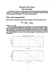
Fig. 4 Plots of the oscillation frequencies and the amplitude of iO1 versus bias current I -89.7
0.05
(17) Amplitude Matching (dB): iO3 / iO1
⎡ ⎢ ⎢⎣
2I ⎛ Ca ⎞ ⎤ ⎜ A0 ⎟ ⎥ (VGS3 − VT )Cb ⎝ Cb ⎠ ⎥⎦
10
Simulated Oscillation Frequency
1.2
As mentioned earlier in Section IIB, τa = Ca/gm1 and τb = Cb/gm3, substituting τa and τb in (14) with (τa = Ca/gm1) and (τb = Cb/gm3) yields ω0 = (gm3/Cb) / [A0(Ca/gm1)(gm3/Cb)]-1/2. As τa can be equal to τb (i.e. gm1 = gm3 and Ca = Cb), therefore
ω0 =
1.8
Amplitude (dB)
τb
τb ⎡ ⎛ τ a′ ⎞ ⎤ ⎢τ c ⎜ 1 + ⎟ + τ a′ ⎥ ⎣ ⎝ τb ⎠ ⎦
15
It can be seen from (17) that ω0 is tunable through the bias current I. Such an oscillator employs a low-pass-filter-based all-current-mirror technique based on (i) inherent time constants of current mirrors as described in (14) or (17), i.e. the internal capacitances and the transconductance of a diodeconnected NMOS, (ii) a simple negative resistance RN formed by a resistor load RL of a current mirror as described in (7).
-89.8
Phase Angle
0.03
-89.9
0.01
-90 -0.01
-90.1
-0.03
-90.2
Amplitude
-0.05 1.4
-90.3 1.5
1.6
1.7
1.8
1.9
Phase Matching (deg) = (phase of iO3) - (phase of iO1)
1
Frequency fo (GHz)
ω0 =
2.0
2.0
Oscillation Frequency (GHz)
III. SIMULATION RESULTS
Fig. 5 Amplitude and phase matching of the quadrature signals versus frequency
The performance of the circuit shown in Fig. 2 has been simulated through SPICE. As mentioned earlier, transistors are modeled by Alcatel Mietec 0.5 μm CMOS C05MD Technology (AMC) of EUROPRACTICE. The minimum width W and length L of a transistor are 0.8 μm and 0.5 μm, respectively. The unity-gain frequency (fT) of an NMOS Qi in this particular example is approximately 7.56 GHz. The supply voltage Vdd = 2 V and R1 = 18 kΩ. For purposes of simulation, the values of G0 and RL are practically chosen to be 1.1 and 14 kΩ, respectively.
Fig. 6 Harmonic spectrums through FFT of the oscillogram iO1 previously depicted Fig. 3 and carrier-to-noise ratio (CNR) = 90.01 dBc/Hz at 2 MHz offset from the 1.9 GHz carrier Fig. 3 depicts the resulting cosine and sine oscillograms of the quadrature currents iO1 and iO3, respectively, at I = 20 μA where the oscillation frequency f0 = ω0/(2π) is measured to be 1.9 GHz. Fig. 4 illustrates plots of the oscillation frequencies (GHz) and the amplitudes (dB) of iO1 versus bias current I, where the dotted lines indicate the expected analysis and the solid lines indicate the SPICE analysis. As shown in Fig. 4,
Fig. 3 Oscillograms of quadrature currents iO1 and iO3 at 1.9 GHz and I = 20 μA
21
International Journal of Applied Science, Engineering and Technology Volume 3 Number 1
APPENDIX A1
the oscillation frequencies are tunable over a range from 1.53 to 1.9 GHz by the bias current I from 13 to 20 uA, respectively, and therefore the tuning range is approximately 370 MHz or 21.6%. Fig. 5 depicts the amplitude matching (dB) in terms of the ratio iO3 / iO1 as well as the quadrature phase matching (degrees) in terms of (θO3−θO1) of the quadrature currents versus frequency. The amplitude matching is as near as 0.029 dB whilst the quadrature phase matching for −90° is better than 0.15°. Fig. 6 shows the power spectrum levels (dBm) of the fundamental frequency at 1.9 GHz and the next harmonics of the oscillogram iO1 previously depicted in Fig. 3 using a commercially available fast Fourier transform (FFT) program. As shown in Fig. 6, the distortions are due mainly to the presence of the second harmonics, which is approximately 51.5 dB down from the fundamental frequency, and they remain essentially at the same magnitude over the entire operational bias-current range (13 μA to 20 μA). Consequently, the total harmonic distortions (THD) are less than 0.3 %. As shown in Fig. 6, the phase noise is equal to −90.01 [dBc/Hz] at 2 MHz offset from the 1.9 GHz carrier. In other words, CNR = 90.01 dBc/Hz at Δf = 2 MHz and f0 = 1.9 GHz. It can be seen from Fig. 2 that the total current consumption of the oscillator is equal to 8I + 3G0I. For I = 20 μA and G0 = 1.1, the power dissipation (PDC) is only 0.452 mW. Consequently, the figure of merit [23] called CNRnorm = 153.03 dBc/Hz.
Fig. A1 Input impedances of three current-mirror (CM) filters F1, F2 and F3 : (a) Zin of filter F′1 at node N, (b) Zini of filter F′2 at node P, (c) Zinii of filter F′3 at node N′, (d) Ziniii of filter F′4 at node P′ and (e) Ziniv of CM filter F3 at node T
APPENDIX A2 Analytical treatments for the results shown in equation (14)
IV. CONCLUSION The high-frequency low-power all-current-mirror sinusoidal quadrature oscillator has been presented through the use of two 2nd-order low-pass current mirror (CM)-based filters (F1 and F2), a 1st-order CM low-pass filter (F3) and a CM bilinear transfer function (F4). The bilinear transfer function (F4) is described in terms of a negative resistance (RN = -RL) where RL is a resistor load of a current mirror. The technique is relatively simple based on (i) inherent time constants of current mirrors, i.e. the internal capacitances and the transconductance of a diode-connected NMOS, (ii) a simple negative resistance RN formed by a resistor load RL of a current mirror. Neither external capacitances nor inductances are required. As a particular example of the second technique, a 1.9GHz, 0.45-mW, 2-V CMOS low-pass-filter-based all-currentmirror sinusoidal quadrature oscillator has been demonstrated in this Chapter. The oscillation frequency (f0) is 1.9 GHz and is current-tunable over a range of 370 MHz or 21.6 %. The power consumption is at approximately 0.45 mW. The amplitude matching and the quadrature phase matching are better than 0.05 dB and 0.15°, respectively. Total harmonic distortions (THD) are less than 0.3 %. At 2 MHz offset from the 1.9 GHz, the carrier to noise ratio (CNR) is 90.01 dBc/Hz whilst the figure of merit called a normalized carrier-to-noise ratio (CNRnorm) is 153.03 dBc/Hz. The ratio of the oscillation frequency (f0) to the unity-gain frequency (fT) of a transistor is 0.25. Comparisons to other approaches have also been included.
22
International Journal of Applied Science, Engineering and Technology Volume 3 Number 1
[2]
APPENDIX A3 Analytical treatments for the results shown in equation (15)
[3] [4]
[5]
[6] [7] [8]
[9]
[10]
[11]
[12] [13]
[14]
[15]
[16]
[17]
[18]
[19]
[20]
[21]
[22]
REFERENCES [1]
J. Fenk, “Highly Integrated RF-IC’s for GSM and DECT Systems-A Status Review,” IEEE Transaction on Microwave Theory and Techniques, vol. 45 (12), pp. 2531-2539, 1997.
[23]
23
B. Razavi, “Design Considerations for Direct-Conversion Receivers,” IEEE Transaction on Circuits and System-II, vol. 44, pp. 428-435, 1997. A. Parssinen, Direct Conversion Receivers in Wide-Band Systems, Klumer Academic Plublishers, 2001. F. Gatta, D. Manstretta, P. Rossi, and F. Svelto, “A Fully Integrated 0.18-μm CMOS Direct Conversion Receiver Front-End with On-Chip LO for UMTS,” IEEE Journal of Solid-State Circuits, vol. 39(1), pp. 1523, 2004. J.B. Hughes, A. Spencer, A. Worapishet, and R. Sitdhikorn, “1 mW CMOS Polyphase Channel Filter for Bluetooth,” IEE Proc.-Circuits Devices Syst., vol. 149 (5/6), pp. 348-354, 2002. D.A. Johns, and K. Martin, Analog Integrated Circuit Design, (New York: John Wiley & Sons), 1997. A. Sedra, and K.C. Smith, Microelectronic Circuits, 4th edn., (New York: Oxford University Press), 1998, pp. 984-986 and 441-444. B. Srisuchinwong, “Fully balanced current-tunable sinusoidal quadrature oscillator,” International Journal of Electronics, vol. 87, pp. 547-556, 2000. K. Kumwachara, and W. Surakampontorn, “An Integrable TemperatureInsensitive gm-RC Quadrature Oscillator,” International Journal of Electronics, vol. 90 (9), pp. 599-605, 2003. C. Cakir, U. Cam, and O. Cicekoglu, “Novel Allpass Filter Configuration Employing Single OTRA,” IEEE Transaction on Circuits and System-II: Express Briefs, vol. 52 (3), pp. 122-125, 2005. J.W. Horng, H.P. Chou and I.C. Shiu, “Current-mode and Voltage-Mode Quadrature Oscillator Employing Multiple Outputs CCIIs and Grounded Capacitors,” Proceeding of the 2006 IEEE International Symposium on Circuits and Systems, May 2006. S. Pookaiyaudom and K. Samootrut, “Current-Mirror Phase-Shifter Oscillator,” Electronics Letters, vol. 23, pp. 21-23, 1987. S. Pookaiyaudom and R. Sitdhikorn: “Current-Differencing Band-Pass Filter Realization with Application to High-Frequency Electronically Tunable Low-Supply-Voltage Current-Mirror-Only Oscillator,” IEEE Transaction on Circuits and System-II, vol. 43, no. 12, pp.832-835, 1996. S. Pookaiyaudom and J. Mahattanakul, “A 3.3 volt high-frequency capacitorless electronically-tunable log-domain oscillator,” Proceeding of the 1995 IEEE International Symposium on Circuits and Systems, vol. 2, pp. 829-832, 1995. A. Leelasantitham and B. Srisuchinwong, “A low-power, highfrequency, all-NMOS all-current-mirror sinusoidal quadrature oscillator,” Microelectronics Journal, vol. 35, pp. 713-721, 2004. B. Razavi, “A 1.8 GHz CMOS Voltage-Controlled Oscillator,” Proceedings of the 1997 IEEE International Solid-State Circuits Conference, pp. 388-389, 1997. H.-S. Kao and C.-Y. Wu, “A Compact CMOS 2V Low-Power DirectConversion Quadrature Modulator Merge with Quadrature VoltageControlled Oscillator and RF Amplifier for 1.9GHz RF Transmitter Applications,” Proceedings of the 2000 IEEE International Symposium on Circuits and Systems, vol. 4, pp. 765-768, 2000. P. Andreani, “A Low-Phase-Noise Low-Phase-Error 1.8GHz Quadrature CMOS VCO,” Proceedings of the 2002 IEEE International Solid-State Circuits Conference, vol. 2, pp. 228-229, 2002. S.B. Anand and B. Razavi, “A CMOS Clock Recovery Circuit for 2.5Gb/s NRZ Data,” IEEE Journal of Solid-State Circuits, vol. 36 (3), pp. 432-439, 2001. D.P. Bautista and M.L. Aranda, “A Low Power and High Speed CMOS Voltage-Controlled Ring Oscillator,” Proceeding of the 2004 IEEE International Symposium on Circuits and Systems, vol. 4, pp. 752-755, 2004. J. van der Tang and D. Kasperkovitz, “A 0.9-2.2GHz Monolithic Quadrature Mixer Oscillator for Direct-Conversion Satellite Receivers,” Proceedings of the 1997 IEEE International Solid-State Circuits Conference, vol. 40, pp. 88-89, 1997. S. Finocchiaro, G. Palmisano, R. Salerno and C. Sclafani, “Design of Bipolar RF Ring Oscillators,” Proceedings of the 6th IEEE International Conference on Electronics, Circuits and Systems (ICECS’99), vol. 1, pp. 5-8, 1999. W. Sansen, J.H. Huijsing and R.J. van de Plassche (Eds.), Analog Circuit Design, Klumer Academic Publishers, 1999, pp. 353-381.