First-order lowpass filter. ▫ Cascade connection and Logarithmic frequency
scales. ▫ Bode Plots. Reading. ▫ Chap 6-6.5. EE40 Summer 2005: Lecture 8.
Announcements
Midterm #1
Tuesday
July 12, 11:30 am – 1pm in 145 Dwinelle
Non-programmable calculators allowed
1 double-sided cheat sheet allowed. Must be hand made
Material up to and including lecture 7
Midterm Review Session
Monday
July 11, 5 – 8pm in 277 Cory
Attend only your second lab slot next week
EE40 Summer 2005: Lecture 8
Instructor: Octavian Florescu
1
Review
Phasors
Source
First Order Circuits
Initial
vs. Impedence representation
and Final conditions
Second Order Circuits
Solution
EE40 Summer 2005: Lecture 8
Instructor: Octavian Florescu
2
1
Lecture #8 OUTLINE
Decibels Transfer function First-order lowpass filter Cascade connection and Logarithmic frequency scales Bode Plots
Reading
Chap 6-6.5
EE40 Summer 2005: Lecture 8
Instructor: Octavian Florescu
3
Bel and Decibel (dB)
A bel (symbol B) is a unit of measure of ratios of power levels, i.e. relative power levels.
The bel is too large for everyday use, so the decibel (dB), equal to 0.1B, is more commonly used.
The name was coined in the early 20th century in honor of Alexander Graham Bell, a telecommunications pioneer. The bel is a logarithmic measure. The number of bels for a given ratio of power levels is calculated by taking the logarithm, to the base 10, of the ratio. one bel corresponds to a ratio of 10:1. B = log10(P1/P2) where P1 and P2 are power levels.
1dB = 10 log10(P1/P2)
dB are used to measure
Electric power, Gain or loss of amplifiers, Insertion loss of filters.
EE40 Summer 2005: Lecture 8
Instructor: Octavian Florescu
4
2
Logarithmic Measure for Power
To express a power in terms of decibels, one starts by choosing a reference power, Preference, and writing Power P in decibels = 10 log10(P/Preference) Exercise:
Exercise:
Express a power of 50 mW in decibels relative to 1 watt. P (dB) =10 log10 (50 x 10-3) = - 13 dB Express a power of 50 mW in decibels relative to 1 mW. P (dB) =10 log10 (50) = 17 dB.
dBm to express absolute values of power relative to a milliwatt.
dBm = 10 log10 (power in milliwatts / 1 milliwatt) 100 mW = 20 dBm 10 mW = 10 dBm
EE40 Summer 2005: Lecture 8
Instructor: Octavian Florescu
5
Aside About Resonant Circuits
When dealing with resonant circuits it is convenient to refer to the frequency difference between points at which the power from the circuit is half that at the peak of resonance. Such frequencies are known as “half-power frequencies”, and the power output there referred to the peak power (at the resonant frequency) is 10log10(Phalf-power/Presonance) = 10log10(1/2) = -3 dB.
EE40 Summer 2005: Lecture 8
Instructor: Octavian Florescu
6
3
Logarithmic Measures for Voltage or Current From the expression for power ratios in decibels, we can readily derive the corresponding expressions for voltage or current ratios. Suppose that the voltage V (or current I) appears across (or flows in) a resistor whose resistance is R. The corresponding power dissipated, P, is V2/R (or I2R). We can similarly relate the reference voltage or current to the reference power, as Preference = (Vreference)2/R or Preference= (Ireference)2R. Hence, Voltage, V in decibels = 20log10(V/Vreference) Current, I, in decibels = 20log10(I/Ireference) EE40 Summer 2005: Lecture 8
Instructor: Octavian Florescu
7
Note that the voltage and current expressions are just like the power expression except that they have 20 as the multiplier instead of 10 because power is proportional to the square of the voltage or current. Exercise: How many decibels larger is the voltage of a 9-volt transistor battery than that of a 1.5-volt AA battery? Let Vreference = 1.5. The ratio in decibels is 20 log10(9/1.5) = 20 log10(6) = 16 dB.
EE40 Summer 2005: Lecture 8
Instructor: Octavian Florescu
8
4
Transfer Function
Transfer function is a function of frequency
Complex
quantity
Both magnitude and phase are function of frequency Vin
H( f ) =
Two Port filter network
Vout
Vout Vout = ∠ (θ out − θ in ) Vin Vin
H(f) = H ( f ) ∠ θ
EE40 Summer 2005: Lecture 8
Instructor: Octavian Florescu
9
Filters
Circuit designed to retain a certain frequency range and discard others Low-pass: pass low frequencies and reject high frequencies High-pass: pass high frequencies and reject low frequencies Band-pass: pass some particular range of frequencies, reject other frequencies outside that band Notch: reject a range of frequencies and pass all other frequencies
EE40 Summer 2005: Lecture 8
Instructor: Octavian Florescu
10
5
Common Filter Transfer Function vs. Freq H(f )
H(f )
Low Pass
High Pass
Frequency
Frequency
H(f )
H(f )
Band Reject
Band Pass Frequency
EE40 Summer 2005: Lecture 8
Frequency
Instructor: Octavian Florescu
11
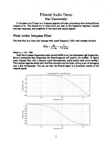
First-Order Lowpass Filter H(f) =
VC 1 ( jω C ) 1 = = = V 1 ( jω C ) + R 1 + jω RC
1 1 + (ω RC )
2
∠ − tan −1 (ω RC )
1 1 and f B = 2π RC RC H(f) = H ( f ) ∠ θ Let ω B =
H(f)=
1 ⎛ f ⎞ 1+ ⎜ ⎟ ⎝ fB ⎠
2
⎛ f ⎞ , θ = − tan −1 ⎜ ⎟ ⎝ fB ⎠
1 H ( fB ) = = 2−1/ 2 2 H ( fB ) 1 = 20(− ) log10 2 = −3 dB 20 log10 H (0) 2 EE40 Summer 2005: Lecture 8
+ V -
Instructor: Octavian Florescu
R
+ VC
C -
12
6
First-Order Highpass Filter H(f) =
VR R jω RC = = = V 1 ( jω C ) + R 1 + jω RC
H(f)=
⎛ f ⎞ ⎜ ⎟ ⎝ fB ⎠ ⎛ f ⎞ 1+ ⎜ ⎟ ⎝ fB ⎠
2
,θ =
π 2
(ω RC ) 2 1 + (ω RC )
⎡π ⎤ ∠ ⎢ − tan −1 (ω RC ) ⎥ 2 ⎣ ⎦
⎛ f ⎞ − tan − 1 ⎜ ⎟ ⎝ fB ⎠
VR
1 = 2−1/ 2 2 H ( fB ) 1 = 20(− ) log10 2 = −3 dB 20 log10 H (0) 2 H ( fB ) =
EE40 Summer 2005: Lecture 8
+ V -
R
+ VC
C -
Instructor: Octavian Florescu
13
First-Order Lowpass Filter ⎛ ωL ⎞ ∠ − tan −1 ⎜ ⎟ ⎝ R ⎠ ⎛ωL ⎞ 1+ ⎜ ⎟ ⎝ R ⎠ R R Let ω B = and f B = 2π L L H(f) = H ( f ) ∠ θ H(f) =
1 VR = = jω L V +1 R
H(f)=
1 ⎛ f ⎞ 1+ ⎜ ⎟ ⎝ fB ⎠
2
EE40 Summer 2005: Lecture 8
1
2
⎛ f ⎞ , θ = − tan −1 ⎜ ⎟ ⎝ fB ⎠
VR + V -
Instructor: Octavian Florescu
R
+ VL
L -
14
7
First-Order Highpass Filter jω L VL R = = H(f) = jω L V +1 R
ωL
⎡π ⎛ ω L ⎞⎤ ∠ ⎢ − tan − 1 ⎜ ⎟⎥ 2 ⎝ R ⎠⎦ ⎣ ⎛ ωL ⎞ 1+ ⎜ ⎟ ⎝ R ⎠ R R Let ω B = and f B = L 2π L H(f) = H ( f ) ∠ θ
H(f )=
R
2
VR
⎛ f ⎞ ⎜ ⎟ ⎝ fB ⎠ ⎛ f ⎞ 1+ ⎜ ⎟ ⎝ fB ⎠
2
,θ =
π 2
⎛ f ⎞ − tan − 1 ⎜ ⎟ ⎝ fB ⎠
EE40 Summer 2005: Lecture 8
R
+ V -
+ VL
L -
Instructor: Octavian Florescu
15
First-Order Filter Circuits High Pass
VS
+ –
R C
Low Pass
Low Pass
VS
+ –
R L
High Pass
HR = R / (R + 1/jωC)
HR = R / (R + jωL)
HC = (1/jωC) / (R + 1/jωC)
HL = jωL / (R + jωL)
EE40 Summer 2005: Lecture 8
Instructor: Octavian Florescu
16
8
Gain or Loss Expressed in Decibels The gain produced by an amplifier or the loss of a filter is often specified in decibels. The input voltage (current, or power) is taken as the reference value of voltage (current, or power) in the decibel defining expression: Voltage gain in dB = 20 log10(Voutput/Vinput) Current gain in dB = 20 log10(Ioutput/Iinput Power gain in dB = 10 log10(Poutput/Pinput) Example: The voltage gain of an amplifier whose input is 0.2 mV and whose output is 0.5 V is 20log10(0.5/0.2x10-3) = 68 dB. EE40 Summer 2005: Lecture 8
Instructor: Octavian Florescu
17
Change of Voltage or Current with a Change of Frequency One may wish to specify the change of a quantity such as the output voltage of a filter when the frequency changes by a factor of 2 (an octave) or 10 (a decade). For example, a single-stage RC low-pass filter has at frequencies above ω = 1/RC an output that changes at the rate -20dB per decade.
EE40 Summer 2005: Lecture 8
Instructor: Octavian Florescu
18
9
Bode Plot
Plot of magnitude of transfer function vs. frequency
Both
x and y scale are in log scale
Y scale in dB
Log Frequency Scale
Decade
Æ Ratio of higher to lower frequency
= 10
Octave Æ Ratio of higher to lower frequency =2
EE40 Summer 2005: Lecture 8
Instructor: Octavian Florescu
19
High-frequency asymptote of Lowpass filter The high frequency asymptote of magnitude Bode plot assumes -20dB/decade slope As f → ∞ −1
⎛ f ⎞ H(f ) =⎜ ⎟ ⎝ fB ⎠ H (10 f B ) = − 20 dB 20 log 10 H ( fB )
EE40 Summer 2005: Lecture 8
Instructor: Octavian Florescu
20
10
Low-frequency asymptote of Highpass filter As f → 0
H(f )=
⎛ f ⎞ ⎜ ⎟ ⎝ fB ⎠ ⎛ f ⎞ 1+ ⎜ ⎟ ⎝ fB ⎠
2
⎛ f ⎞ →⎜ ⎟ ⎝ fB ⎠
f →∞
20 log 10
H ( fB ) = 20 dB H (0.1 f B )
The low frequency asymptote of magnitude Bode plot assumes 20dB/decade slope EE40 Summer 2005: Lecture 8
Instructor: Octavian Florescu
21
Second-Order Filter Circuits
Band Pass R VS
+ –
Z = R + 1/jωC + jωL
Low Pass
C
High Pass
L
EE40 Summer 2005: Lecture 8
HBP = R / Z Band HLP = (1/jωC) / Z Reject
HHP = jωL / Z
HBR = HLP + HHP
Instructor: Octavian Florescu
22
11