International Conference on Unmanned Aircraft Systems (ICUAS), Denver, USA, 2015.
A High-performance MAV for Autonomous Navigation in Complex 3D Environments Marius Beul, Nicola Krombach, Yongfeng Zhong, David Droeschel, Matthias Nieuwenhuisen, and Sven Behnke
Abstract— Micro aerial vehicles, such as multirotors, are particular well suited for the autonomous monitoring, inspection, and surveillance of buildings, e.g., for maintenance in industrial plants. Key prerequisites for the fully autonomous operation of micro aerial vehicles in complex 3D environments include real-time state estimation, obstacle detection, mapping, and navigation planning. In this paper, we describe an integrated system with a multimodal sensor setup for omnidirectional environment perception and 6D state estimation. Our MAV is equipped with a variety of sensors including a dual 3D laser scanner, three stereo camera pairs, an IMU and a powerful onboard computer to achieve these tasks in real-time. Our experimental evaluation demonstrates the performance of the integrated system.
I. I NTRODUCTION Micro aerial vehicles (MAVs) are enjoying increasing popularity, both in research and in applications such as aerial photography, inspection, surveillance, and search and rescue missions. Most MAVs are remotely controlled by a human operator or follow GPS waypoints in obstacle-free heights. For autonomous navigation in complex 3D environments, sufficient onboard sensors and computing power are needed in order to perceive and avoid obstacles, build 3D maps of the environment and plan flight trajectories. In this article, we present an MAV with a multimodal omnidirectional sensor setup, a fast onboard computer and a robust data link. The sensors include a lightweight dual 3D laser scanner and three stereo cameras. All components are lightweight and hence well suited for MAVs. This work has been supported by a grant of the Bundesministerium f¨ur Wirtschaft und Energie in the Autonomics for Industry 4.0 project InventAIRy. The authors are with the Autonomous Intelligent Systems Group, Computer Science VI, University of Bonn, Germany
[email protected]
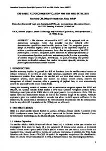
Fig. 1. Our MAV has been designed for short-range inspection tasks. Reliable perception of obstacles in the surrounding is key for safe operation.
Our MAV can localize in indoor environments by means of laser-based localization and avoids static and dynamic obstacles perceived with the onboard sensors reliably. II. R ELATED W ORK In recent years, many MAVs with onboard environment sensing and navigation planning have been developed. Due to the limited payload of MAVs, most approaches to obstacle avoidance are camera-based [1]–[8]. Approaches using monocular cameras to detect obstacles require translational movement in order to perceive the same surface points from different perspectives. In order to estimate depth of object points instantaneously, stereo cameras are used on MAVs, e.g., in the works of Schmid et al. [3] and Park and Kim [8]. Tripathi et al. [5] use stereo cameras for reactive collision avoidance. The limited field of view (FoV) of cameras poses a problem when flying in constrained spaces where close obstacles can surround the MAV.
To overcome these limitations, some MAVs are equipped with multiple (stereo) cameras. Schauwecker and Zell [7] use two stereo cameras, one oriented forward, the other backward. Moore et al. [9] use a ring of small cameras to achieve an omnidirectional view in the horizontal plane, but rely on optical flow for speed control, centering, and heading stabilization only. Grzonka et al. [10] use a 2D laser scanner to localize the MAV in environments with structures in flight height and to avoid obstacles. This limits obstacle avoidance to the measurement plane of the laser scanner. Other groups combine laser scanners and visual obstacle detection [11]–[13]. Still, their perceptual field is limited to the apex angle of the stereo camera (facing forward), and the mostly horizontal 2D measurement plane of the scanner. They do not perceive obstacles above or below this region or behind the vehicle. We allow omnidirectional 4D movements (3D position and yaw) of our MAV, thus we have to take obstacles in all directions into account. The proposed MAV extends our own previous work [14], an MAV with a 3D laser scanner and two wide-angle stereo camera pairs. Another MAV with a sensor setup that allows omnidirectional obstacle perception is described by Chambers et al. [15]. We significantly increase field of view and bandwidth of the onboard cameras, add a second laser scanner to measure simultaneously in orthogonal directions, and use a faster onboard computer. In combination with accurate pose estimation laser scanners are used to build 3D maps. Fossel et al., for example, use Hector SLAM [16] for registering horizontal 2D laser scans and OctoMap [17] to build a three-dimensional occupancy model of the environment at the measured heights [18]. Morris et al. follow a similar approach and in addition use visual features to aid state estimation [19]. Still, perceived information about environmental structures is constrained to lie on the 2D measurement planes of the moved scanner. In contrast, we use a continuously rotating laser scanner that does not only allow for capturing 3D measurements without moving, but also provides omnidirectional obstacle sensing at comparably high frame rates (4 Hz in our setup).
III. S YSTEM OVERVIEW Our MAV design is a hexarotor with a frame surrounding the rotor plane. Fig. 1 shows our MAV in a typical indoor environment. While fragile equipment like computer and laser scanner lie in the core of the MAV, the frame protects the rotors and is used for mounting multiple sensors. For sensor data processing and navigation planning, we use a Gigabyte GB-BXi7-4770R as the onboard processing system. The mini-ITX board is equipped with an Intel Core i7-4770R quadcore CPU, 16 GB DDR3-memory and a 480 GB SSD. For state estimation, obstacle detection, localization and mapping, our MAV is equipped with a multimodal sensor setup. Fig. 2 shows an overview of the installed sensors. Our MAV features a ring of six 1.3 M Pixel USB 3.0 cameras, yielding an omnidirectional FoV. The cameras are used for visual odometry (VO), obstacle detection, and for the detection of visual features like AprilTags [20]. We use two rotating Hokuyo UST-20LX laser scanners to achieve a comprehensive perception of the MAV surroundings. Each laser scanner provides a scanning range of up to 20 m with 270◦ apex angle. The 3D laser is used for obstacle perception and 6D localization in a SLAM-based map. For high-level navigation tasks, we employ the Robot Operating System (ROS [21]) as middleware on the onboard computer and on a ground control station. For low-level velocity and attitude control, the MAV is equipped with a Pixhawk Autopilot flight control unit [22] that also contains gyroscopes, accelerometers, a compass, and a barometer. We modified its firmware to meet our requirements. In contrast to the original implementation, we control the MAV by egocentric velocity commands calculated by the onboard PC. Hence, we need a reliable egocentric velocity estimate, independent from allocentric measurements, i.e., compass orientation. Our filter integrates, besides the measurements already considered in the original implementation, external sources provided by the onboard PC. These include visual odometry velocities and laser-based localization. To achieve high camera frame rates at full resolution, a distribution of the USB workload to different buses is necessary. We connect the
Fig. 2. Scheme of the sensors, actuators, computers, and bus systems on our MAV. We use high bandwidth USB 3.0 connection for the cameras due to the high data rates, and lower bandwidth buses for laser and flight control. The dashed lines indicate a WiFi connection and a connection inactive during flights.
cameras via three hubs, one per stereo pair, to a dedicated USB 3.0 bus of the onboard computer. Onboard components with lower bandwidth requirements, i.e., the flight control unit and the laser scanner rotator, are connected to a second USB 2.0 bus. The Pixhawk Autopilot is connected twice. The first connection via an USB-to-serial converter provides the telemetry and control connection according to the MAVLink protocol [23]. The second connection is inactive during flight and only used for debugging and firmware updates of the Pixhawk Autopilot on the ground. Fig. 2 illustrates our onboard USB setup. While our MAV frame also supports the use of 15” propellers, we use six MK3644/24 motors (111 g each) with 14” propellers to generate thrust. Turnigy 5S, 10Ah, 35C batteries power the MAV, including all periphery. The batteries weight 1.28 kg each and are hot-swappable. Thus, it is not necessary to shutdown the onboard computer while changing batteries. There are several components on the MAV that
emit radio waves. We evaluated the influence of these components on each other by identifying the relevant frequencies in a series of tests. Table I gives an overview on the components and frequencies. Although it does not show the exact emission spectrum, it provides initial information which frequencies ranges are prone to interference for further investigation. It can be seen that the computer memory is working at the same clock frequency as the GNSS sources. We found that it emits interference radiation preventing a stable GNSS reception. Since we experienced strong interference especially with GPS, the GNSS antenna is placed as far as possible from the jamming source to reduce noise. This leads to a stable reception of the GPS signal. We did not experience other noteworthy interferences. Real-time debugging and control of onboard functions is crucial for the efficient development of algorithms. To ensure seamless operation, we use two Ubiquity Networks BulletTM BM5HP WiFi adapters. They are configured to work in Wireless
(a) Triple stereo configuration
(b) Omnidirectional configuration
Fig. 3. Mounting of the cameras in (a) triple stereo and (b) omnidirectional configuration. Configuration (a) facilitates the usage of available standard stereo methods. In configuration (b) cameras have partial image overlap with both neighboring cameras. This allows the development of truly omnidirectional vision methods. TABLE I MAV
COMPONENTS EMITTING AND / OR RECEIVING RADIO WAVES .
Component
Frequency (GHz)
GPS L1
1.57542
GPS L2
1.2276
GLONASS L1
1.6
Computer CPU
0.8 - 3.2
Computer memory
1.6
WiFi
5.15 - 5.725
Remote Control
2.4
Distribution System (WDS) Transparent Bridge Mode to behave as if a wired connection would be present. Our network setup is also shown in Fig. 2. Benchmarking the network gives a real throughput of 7.5 MB/s. Latency analysis gives an average ping of 1.22 ms ± 0.11 ms. We aim for a fully autonomous system, so no data has to be exchanged between the ground control stations and the MAV in normal operation modes. However, this benchmark shows that the communication infrastructure enables the operators to visualize point clouds or even view live video feeds with ∼ 2 Hz for debugging purposes. IV. P ERCEPTION A. Accelerometers, gyros, compass, and barometer Low-level sensors like accelerometers and gyros are directly connected to the Pixhawk Autopilot to ensure real-time processing of these comparatively fast sensors. For a fast transient response, state
estimation—detailed in Sec. V—runs directly on the Pixhawk. Hence, raw data of accelerometers, gyros, compass and barometer are not fed to the main computer, but processed directly on the flight control unit. B. Cameras We use six XIMEA MQ013MG-E2 globalshutter grayscale USB 3.0 cameras (22.5 g each) for visual perception. The camera configuration can be easily switched from three stereo-pairs (Fig. 3a) to an omnidirectional configuration including all six cameras (Fig. 3b). The mountings are detailed in Fig. 4. We use vibration dampeners to isolate the cameras from high frequency oscillations caused by the imbalance of the propellers. Each mounting including dampeners weights 11.5 g. In combination with Lensagon BF2M2020S23 fish-eye lenses (25 g each), an omnidirectional FoV can be obtained. The use of multiple camera pairs not only facilitates omnidirectional obstacle perception, but also provides redundancy. So if, e.g., the MAV points one camera-pair towards featureless surfaces or the sky, the others are still able to perceive the environment. With every pair of stereo cameras sharing a separate bus, we achieve frame rates of up to 55 fps. All cameras are synchronized by hardware triggering. When data of all cameras is received, the next frame is triggered. This enables us to achieve adaptive high frame rates which results
Fig. 4. To cope with unavoidable vibrations during flights, our camera mounts are equipped with vibration dampeners. The left mount is for stereo configuration, the right mount for omnidirectional camera configuration.
Fig. 6. Photo and CAD drawing of our 3D laser scanner with the FoV of the individual 2D laser scanners (blue). The Hokuyo 2D LRFs are mounted on a bearing and rotated around the red axis.
leads to many measurements lying on the MAV itself. Considering the complex structure of the MAV, with moving parts like propellers, we do not use an exact self filter that is based on a model of the MAV, but discard measurements that are in an extended bounding box of the MAV. We also make use of a modified jumping edge filter to remove not only incorrect measurements at the edges of the geometry, but also erroneous measurements caused by the fast rotating propellers.
Fig. 5.
Fish-eye camera image of one of the onboard cameras.
in data rates of up to 200 MB/s. Fig. 5 shows an image, obtained during flight, where the MAV mission is to inspect the tubes shown in Fig. 1. C. Laser Scanner The 3D laser perceives the space around our MAV at a frequency of 4 Hz. Each 2D laser has a scanning frequency of 40 Hz with 1, 080 measurements per scan plane resulting in 43, 200 measurements per second. Fig. 6 shows that one scanning plane is parallel to the axis of rotation while the other is twisted by 45◦ . This setup maximizes the FoV while minimizing the blind spot caused by the MAV itself. Fig. 7 shows resulting point clouds of the environment perceived by each laser and the combined point cloud. Each scanner weights 143 g (without cables). The whole sensor assembly weights 420 g including motor, a network switch, and a slip ring allowing for continuous rotation. The wide FoV of the laser scanner inherently
V. S TATE ESTIMATION AND CONTROL In order to navigate in indoor and outdoor environments, robust state estimation, especially in GNSS-denied environments, is crucial. We use two filters for state estimation: A lowlevel extended Kalman filter (EKF) fuses measurements from accelerometers, gyros, and compass to one 6D attitude and acceleration estimate. The second, higher-level, filter fuses acceleration, velocity, and position information to a state estimate that includes 3D position. The low-level filter is supplied with the Pixhawk. The higher-level filter extends the original Pixhawk position estimator by incorporating all the sensors present on the MAV into one state. Here, we predict the state:
px py pz x= vx vy vz , ax ay az
(1)
consisting of 3D position p, 3D velocity v, and 3D acceleration a under the assumption of uniform acceleration 1 (2) pk = pk−1 + vk−1 · dt + ak · dt2 , 2 vk = vk−1 + ak · dt, (3) ak = ak−1 . (4)
(a) Laser scanner 1
(b) Laser scanner 2
(c) Combined scans
Fig. 7. Point clouds from the rotating 3D laser scanner. In the combined scan, nearly no occlusions in the vicinity of the MAV. The tripod represents the pose of the MAV. Color encodes height. TABLE II I NFORMATION SOURCES FOR THE POSITION FILTER . Information source
Information
Dimension
typical update rate (Hz)
coordinate frame
typical weighting factor
Attitude EKF
Linear Acceleration
3D
250
egocentric
20
Visual Odometry
Velocity
3D
15
egocentric
0-2
GNSS
Velocity
3D
10
allocentric
2
Barometer
Position
1D
250
allocentric
0.5
Laser-based SLAM
Position
3D
2
allocentric
2
GNSS
Position
3D
10
allocentric
1
If sensor measurements are available, the state is corrected accordingly. For 1D velocity estimates vk,sens , coming from e.g., visual odometry, the state correction is: vk = vk−1 + (vk,sens − vk−1 ) · w · dt, ak = ak−1 + (vk,sens − vk−1 ) · w2 · dt2 .
(5) (6)
Here, w is a weighting factor that indicates the reliability of the inputs. Table II shows the measurements that contribute to the filter result. Egocentric measurements are first transformed into the allocentric frame by the attitude estimate (Eq. 1). This predictor/corrector design offers the following advantages. It • delivers fast transient responses, • works in GNSS-denied environments, and • does not accumulate drift. As can be seen in Fig. 2, we use a USB-toserial converter to communicate with the Pixhawk. We use the maximum rate of 921, 600 baud to achieve a measurement frequency of up to 250 Hz for attitude, velocity, and position updates.
Fig. 8. The MAV is pushed away from an approaching person and the ground by potential field-based obstacle avoidance. Red lines in the right figure depict forces induced by the local obstacle map (cyan boxes) on the MAV.
VI. L OCALIZATION AND NAVIGATION A. Reactive Local Obstacle Avoidance For safe navigation in complex environments fast reliable obstacle avoidance is key. We developed a frequently updated local multiresolution obstacle map and a local reactive potential field-based collision avoidance layer to cope with dynamic and static obstacles. We transferred our previous work on obstacle perception and collision avoidance from our outdoor mapping MAV [14] to the system
presented in this work. Laser scan lines are aggregated in a local multiresolution map with 40 Hz per 2D laser scanner. The MAV-centric obstacle map, depicted in Fig. 8, has higher resolution in the center and coarser resolution with increasing distance to the center, resembling the distance dependent scanner accuracy. The multiresolution property makes frequent updates feasible. Map consistency is ensured by registering 3D scans— locally undistorted by a visual odometry motion estimate—to the map employing multiresolution surfel registration (MRSR) [24]. Obstacles represented in the map induce artificial repulsive forces to parts of the MAV, pushing it into free space. To take the MAV shape into account, we discretize it into 32 cells and apply the force to each cell. The resulting force vector and the velocity control vector from a higher navigation layer yield a resulting velocity command that avoids obstacles, independent of localization. The obstacle avoidance layer runs at 20 Hz. B. Laser-based Indoor Localization In order to localize the robot in GNSS-denied environments, e.g., indoor environments, in an allocentric frame, we register local multiresolution maps to a global map employing MRSR. Our localization provides a 6D pose estimate in the map frame at 2 Hz. This result is incorporated into the MAV state estimate described in Sec. V. In smaller environments, suitable maps can be build ad-hoc from a takeoff position before a mission. In larger environments, we perform laser-based SLAM [25] to acquire a complete map of the environment. The allocentric map is represented by surfels with a uniform size. VII. E XPERIMENTS AND E VALUATION We evaluated our system in flight experiments. Here we measured a flight time between 6 min to 8 min, depending on the flight dynamics. This is sufficient for typical indoor inspection tasks. Also the ability to how-swap batteries compensates for the relatively short flight time. Fig. 7 shows point clouds recorded with the 3D laser scanner. Due to the different angular mounting of the 2D laser scanners (cf. Fig. 6), we minimize the blind spots in the vicinity of the MAV. In other words, shadows e.g., of the frames
TABLE III C AMERA FRAME RATE IS LIMITED BY EXPOSURE TIME . Exposure time (ms)
Frame rate (Hz)
40
17
23
25
17
30
3
50
or propellers usually only occur in measurements of one 2D laser scanner. This results in an omnidirectional FoV with a minimal blind spot. We measured the accuracy of the Hokuyo UST20LX and compared them to the Hokuyo UTM30LX-EW used in our previous work [14]. Indoors, both laser scanners show the same accuracy of ∼ ±10 mm when measuring a 0.5 m distant object. Outdoors, the accuracy of the UTM-30LX-EW stays the same, but the accuracy of the Hokuyo UST-20LX degrades to ∼ ±35 mm. We evaluated the data acquisition speed of the synchronized cameras. Although the maximum frame rate is up to 55 fps, it is limited by the exposure time of the cameras. Table III reports the resulting frame rates. For linear velocity estimation, we use the VO software viso2 [26]. First we rectify the images with the method epipolar image rectification on a plane with an equidistant model as proposed by Abraham and F¨orstner [27]. The resolution of the rectified images is 640×512. The rectified image pairs are fed into three instances of viso2 in parallel —one for each stereo camera pair— to obtain three velocity estimates. The estimated 3D velocities are utilized in the state estimation pipeline. We weight each velocity estimate according to the number of correspondences that are tracked. Fig. 9 shows a typical image set, captured during flight. It can be seen that the VO finds most correspondences correctly, but some false correspondences are produced due to repetitive environment structures and strong illumination differences. Nevertheless, due to the redundant structure and the correspondence-dependent weighting, the VO does not lose track even if one instance finds no correspondence at all. The computation for VO including image rectification is 30 ms per stereo camera image pair.
(a) Front stereo pair
(b) Back-left stereo pair
(c) Back-right stereo pair
Fig. 9. Visualization of the correspondences in the three stereo camera pairs. Correspondences between one stereo pair are colored blue. Feature correspondences tracked by viso2 are colored green (inliers) and red (outliers).
soidal trajectory. Only accelerometer, gyroscopes and one VO estimate is used to correct the filter. Fig. 11 shows the VO input and the filter result. Although the VO loses track (at t = −41 s and t = −34 s), the filter is able to bridge this information gap. In normal operation, this gap would be filled by other velocity estimates.
Fig. 10. Point cloud of the MAV’s surroundings obtained with LSD-SLAM [28].
Fig. 11. Egocentric velocity estimate from VO in forward direction and filter result.
We also evaluated Large-Scale Direct Monocular SLAM (LSD-SLAM) [28] to obtain a point cloud, representing the surroundings of the MAV (Fig. 10). This semi-dense point cloud represents the same environment as Fig. 5. The computation time is 67 ms per camera per image. In order to evaluate the robustness of the filter, we measured the VO velocity while flying a sinu-
We performed experiments with the integrated system. Fig. 12 shows the resulting trajectory of our indoor localization experiment. We build a map with the onboard laser sensors before the mission. During a mission, the 3D laser scans — aggregated over 500 ms — are registered to the map yielding a 6D pose estimate at 2 Hz. The resulting trajectory is globally consistent. To evaluate the local obstacle avoidance, we control the MAV with egocentric velocity commands, i.e., a zero velocity setpoint for movements in the plane and rotations, and a small descent velocity to keep the MAV close to the ground. The obstacle avoidance keeps the MAV at a safe distance to the ground. Fig. 8 shows an experiment where a person approaches the MAV. The MAV avoided all static and dynamic obstacles based on the 3D laser scans. In order to improve the indoor localization of our MAV in environments with repetitive structures, e.g., warehouses or to localize tagged objects, we augment the environment with AprilTags. These tags can be robustly detected in real-time with our wide angle cameras. Fig. 13 shows the detection of AprilTags with 164 mm edge length. The algorithm is able to detect and locate tags in distances of 0.5 m to 5.0 m. The computation time is 10 ms per image. We build maps of AprilTags in
Fig. 12. In GNSS-denied environments we employ laser-based localization. We build a map of the environment (green) and register undistorted 3D scans (red) to the map during flight. This yields a 6D pose estimate (blue). The middle and right figures depict the resulting trajectory of a flight experiment in a hall.
Fig. 13. AprilTags are tracked in the environment. We obtain the position of tracked tags relative to the camera.
an allocentric frame by mapping with known poses based on laser-based localization. Fig. 14 shows the resulting map after an example flight based on the observations of all six cameras. VIII. C ONCLUSION In this paper, we have presented an integrated MAV that is well prepared of perceiving its environment and for planning its actions. We employ a multimodal omnidirectional sensor setup to achieve situation awareness. The sensors have a high data rate for tracking the MAV motion and for quick detection of changes in its environment. Ample onboard processing power in combination with a high bandwidth ground connection
Fig. 14. Map of AprilTag detections from all six cameras during a test flight. Each dot, colored by tag id, is one detection. Clusters of similar tag detections are circled. The tags are projected to the world frame with position estimates from our localization (red arrows). Grid lines indicate 1 m distances.
leads to a system that is suitable to deploy and debug custom algorithms and for conducting further research. The ability to hot-swap batteries and/or ground power supply, makes developing and testing highly efficient. Run-time measurements of VO, visual obstacle detection and tag detection demonstrate that the used algorithms are currently the bottlenecks in the perception pipeline. We will investigate if competing VO solutions like Bundle Adjustment
for Camera Systems (BACS) [29] can deliver faster results. The developed MAV is a high-performance platform for research on autonomous navigation in complex 3D environments. We plan to transfer our algorithms for mapping [30] and planning [31] to this MAV and to extend these. R EFERENCES [1] T. Mori and S. Scherer, “First results in detecting and avoiding frontal obstacles from a monocular camera for micro unmanned aerial vehicles,” in Proc. of the IEEE Int. Conf. on Robotics and Automation (ICRA), 2013. [2] S. Ross, N. Melik-Barkhudarov, K. S. Shankar, A. Wendel, D. Dey, J. A. Bagnell, and M. Hebert, “Learning monocular reactive uav control in cluttered natural environments,” in Proc. of the IEEE Int. Conf. on Robotics and Automation (ICRA), 2013. [3] K. Schmid, P. Lutz, T. Tomic, E. Mair, and H. Hirschm¨uller, “Autonomous vision-based micro air vehicle for indoor and outdoor navigation,” Journal of Field Robotics, vol. 31, no. 4, pp. 537–570, 2014. [4] D. Magree, J. G. Mooney, and E. N. Johnson, “Monocular visual mapping for obstacle avoidance on UAVs,” Journal of Intelligent & Robotic Systems, vol. 74, no. 1-2, pp. 17–26, 2014. [5] A. Tripathi, R. G Raja, and R. Padhi, “Reactive collision avoidance of UAVs with stereovision camera sensors using UKF,” in Advances in Control and Optimization of Dynamical Systems, 2014, pp. 1119–1125. [6] G. Flores, S. Zhou, R. Lozano, and P. Castillo, “A vision and GPS-based real-time trajectory planning for a MAV in unknown and low-sunlight environments,” Journal of Intelligent & Robotic Systems, vol. 74, no. 1-2, pp. 59–67, 2014. [7] K. Schauwecker and A. Zell, “On-board dual-stereo-vision for the navigation of an autonomous MAV,” Journal of Intelligent & Robotic Systems, vol. 74, no. 1-2, pp. 1–16, 2014. [8] J. Park and Y. Kim, “3d shape mapping of obstacle using stereo vision sensor on quadrotor UAV,” in AIAA Guidance, Navigation, and Control Conference, 2014. [9] R. Moore, K. Dantu, G. Barrows, and R. Nagpal, “Autonomous MAV guidance with a lightweight omnidirectional vision sensor,” in Proc. of the IEEE Int. Conf. on Robotics and Automation (ICRA), 2014. [10] S. Grzonka, G. Grisetti, and W. Burgard, “A fully autonomous indoor quadrotor,” IEEE Trans. on Robotics, vol. 28, no. 1, pp. 90–100, 2012. [11] T. Tomi´c, K. Schmid, P. Lutz, A. Domel, M. Kassecker, E. Mair, I. Grixa, F. Ruess, M. Suppa, and D. Burschka, “Toward a fully autonomous UAV: Research platform for indoor and outdoor urban search and rescue,” Robotics Automation Magazine, IEEE, vol. 19, no. 3, pp. 46–56, 2012. [12] S. Huh, D. Shim, and J. Kim, “Integrated navigation system using camera and gimbaled laser scanner for indoor and outdoor autonomous flight of UAVs,” in Proc. of the IEEE/RSJ Int. Conf. on Intelligent Robots and Systems (IROS), 2013. [13] B. Jutzi, M. Weinmann, and J. Meidow, “Weighted data fusion for UAV-borne 3D mapping with camera and line laser scanner,” International Journal of Image and Data Fusion, 2014.
[14] D. Droeschel, M. Nieuwenhuisen, M. Beul, D. Holz, J. St¨uckler, and S. Behnke, “Multi-layered mapping and navigation for autonomous micro aerial vehicles,” Journal of Field Robotics, 2015. [15] A. Chambers, S. Achar, S. Nuske, J. Rehder, B. Kitt, L. Chamberlain, J. Haines, S. Scherer, , and S. Singh, “Perception for a river mapping robot,” in Proc. of the IEEE/RSJ Int. Conf. on Intelligent Robots and Systems (IROS), 2011. [16] S. Kohlbrecher, J. Meyer, O. von Stryk, and U. Klingauf, “A flexible and scalable SLAM system with full 3D motion estimation,” in Proc. of the IEEE Int. Symposium on Safety, Security and Rescue Robotics (SSRR), 2011. [17] A. Hornung, K. M. Wurm, M. Bennewitz, C. Stachniss, and W. Burgard, “OctoMap: An efficient probabilistic 3D mapping framework based on octrees,” Autonomous Robots, vol. 34, pp. 189–206, 2013. [18] J. Fossel, D. Hennes, D. Claes, S. Alers, and K. Tuyls, “OctoSLAM: A 3d mapping approach to situational awareness of unmanned aerial vehicles,” in Proc. of the Int. Conf. on Unmanned Aircraft Systems (ICUAS), 2013. [19] W. Morris, I. Dryanovski, J. Xiao, and S. Member, “3d indoor mapping for micro-uavs using hybrid range finders and multivolume occupancy grids,” in In RSS 2010 workshop on RGBD: Advanced Reasoning with Depth Cameras, 2010. [20] E. Olson, “AprilTag: A robust and flexible visual fiducial system,” in Proc. of the IEEE Int. Conf. on Robotics and Automation (ICRA), 2011. [21] M. Quigley, K. Conley, B. P. Gerkey, J. Faust, T. Foote, J. Leibs, R. Wheeler, and A. Y. Ng, “ROS: An open-source robot operating system,” in ICRA Workshop on Open Source Software, 2009. [22] L. Meier, P. Tanskanen, L. Heng, G. Lee, F. Fraundorfer, and M. Pollefeys, “PIXHAWK: A micro aerial vehicle design for autonomous flight using onboard computer vision,” Autonomous Robots, vol. 33, no. 1-2, pp. 21–39, 2012. [23] L. Meier, “Micro aerial vehicle link protocol (MAVLink),” mavlink.org, 2015. [24] D. Droeschel, J. St¨uckler, and S. Behnke, “Local multiresolution representation for 6D motion estimation and mapping with a continuously rotating 3D laser scanner,” in Proc. of the IEEE Int. Conf. on Robotics and Automation (ICRA), 2014. [25] ——, “Local multi-resolution surfel grids for MAV motion estimation and 3d mapping,” in Proc. of the Int. Conf. on Intelligent Autonomous Systems (IAS), 2014. [26] A. Geiger, J. Ziegler, and C. Stiller, “StereoScan: Dense 3d reconstruction in real-time,” in IEEE Intelligent Vehicles Symposium, 2011. [27] S. Abraham and W. F¨orstner, “Fish-eye-stereo calibration and epipolar rectification,” ISPRS Journal of Photogrammetry and Remote Sensing, vol. 59, no. 5, pp. 278–288, 2005. [28] J. Engel, T. Sch¨ops, and D. Cremers, “LSD-SLAM: Largescale direct monocular SLAM,” in Proc. of the European Conf. on Computer Vision (ECCV), 2014. [29] J. Schneider, T. L¨abe, and W. F¨orstner, “Incremental realtime bundle adjustment for multi-camera systems with points at infinity,” in Int. Arch. Photogramm. Remote Sens. Spatial Inf. Sci. (ISPRS), vol. XL-1/W2, 2013. [30] D. Holz and S. Behnke, “Mapping with micro aerial vehicles by registration of sparse 3d laser scans,” in Proc. of the Int. Conf. on Intelligent Autonomous Systems (IAS), 2014. [31] M. Nieuwenhuisen and S. Behnke, “Layered mission and path planning for MAV navigation with partial environment knowledge,” in Proc. of the Int. Conf. on Intelligent Autonomous Systems (IAS), 2014.