This article has been accepted for inclusion in a future issue of this journal. Content is final as presented, with the exception of pagination. IEEE TRANSACTIONS ON POWER SYSTEMS
1
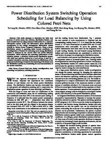
A Linear Three-Phase Load Flow for Power Distribution Systems Alejandro Garces, Member, IEEE Abstract—This letter proposes a linear load flow for three-phase power distribution systems. Balanced and unbalanced operation are considered as well as the ZIP models of the loads. The methodology does not require any assumption related to the ratio. Despite its simplicity, it is very accurate compared to the conventional back-forward sweep algorithm. Index Terms—DC power flow, load flow analysis, power distribution, unbalanced distribution systems. Fig. 1. Schematic representation of the proposed linearization. (a) Values of in the complex plane. (b) Total error in percentage.
I. INTRODUCTION
D
C-power-flow is one of the most studied methodologies for analysis and operation of electric power systems [1]. However, this linear approximation is not suitable for power distribution systems due to their high ratio and unbalanced operation [2]. This letter addresses this issue by using a linear approximation on the complex plane. A radial topology is not required. PV nodes are not considered but distribution generators can be included in the cases in which the grid code compel unity power factor operation for these generators.
lations. The function is analytic for all . Its Taylor series around zero is (3) by neglecting high order terms and defining linear form is obtained
a (4)
II. METHODOLOGY A. Basic Formulation Nodal voltages and currents are related by the admittance matrix as follows: (1) where represents the slack node and is the set of remaining nodes. Each nodal current is related to the voltage by the following ZIP model: (2) where (per unit representation implies ). Notice the ZIP model is linear in except for the constant power loads . This term is approximated in order to obtain a linear power flow.
The error in percentage for this approximation is calculated by defining a function . This function is evaluated in each point inside the filled area in Fig. 1(a) resulting in the filled area in Fig. 1(b). For example, the error for (i.e., ) is around and decreases as approaches 1. This property is used for the power flow formulation. C. Approximated Load Flow A linear expression for the nodal current (2) is obtained as follows: (5) by using (1) and after rearrange some terms, a linear formulation is obtained (6)
B. Linear Approximation A linear approximation is developed on the complex numbers [3] and not on the reals as in the conventional load flow formu-
with (7) (8)
Manuscript received July 02, 2014; revised September 10, 2014; accepted December 12, 2014. Paper no. PESL-00098-2014. The author is with the Department of Electrical Engineering, Universidad Tecnológica de Pereira, Pereira, Colombia (e-mail:
[email protected]. co). Color versions of one or more of the figures in this paper are available online at http://ieeexplore.ieee.org. Digital Object Identifier 10.1109/TPWRS.2015.2394296
(9) Notice that (6) requires to be solved in rectangular representation as follows:
0885-8950 © 2015 IEEE. Personal use is permitted, but republication/redistribution requires IEEE permission. See http://www.ieee.org/publications_standards/publications/rights/index.html for more information.
(10)
This article has been accepted for inclusion in a future issue of this journal. Content is final as presented, with the exception of pagination. 2
where
IEEE TRANSACTIONS ON POWER SYSTEMS
and indicate real and imaginary part, respectively.
D. Extension to the Unbalanced Case The proposed methodology is extendable to three-phase unbalanced power distribution systems. A three-phase admittance matrix is required. are phase-neutral voltages. Subindex in (1) represents in this case three nodes corresponding to each phase. The size of the problem is increased but (6) remains as an accurate approximation. Notice that angles on the three-phase system are not necessarily close to 0, where (3) is valid. Therefore, it is required to define a rotation constant for each node, where according to the phase. On the other hand, for delta connected loads, it is required to define a matrix that converts phase voltage into line voltages [i.e., ]. After including these new terms, the constant matrices in (6) are given by
(11)
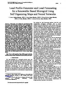
Fig. 2. Error between the back-forward sweep algorithm and the proposed linear power flow. (a) Single phase case. (b) Three-phase unbalanced case.
(12) (13)
TABLE I SIMULATION RESULTS WITH DIFFERENT LOAD MODELS
where is the conventional product and is the Hadamard product (i.e., the Matlab element-wise multiplication).
III. RESULTS In order to illustrate the application of the proposed method, consider the IEEE 37-node test feeder [4]. Loading in this system is very unbalanced. Furthermore, they are delta connected. Results are evaluated in terms of the voltage error. Let us define where is the voltage in the node , calculated by using the conventional back-forward sweep algorithm, and is the voltage calculated by the proposed methodology (do not confuse with defined in the previous section). Results for the three-phase and the singlephase systems are depicted in Fig. 2. Maximum error for the balanced case is . This is a low error for a noniterative load flow. For example, the maximum error for the first iteration of the back-forward sweep algorithm is (i.e., five times higher). Maximum error for the three-phase system is . This error is satisfactory for many practical applications. The error is not affected by the type of loads, unbalance or ratio in distribution lines. However, it is affected by the number of constant power loads and the minimum voltage of the system. Minimum voltage in the IEEE 37-node test feeder is 0.9846 pu. This explains the low error. Simulations were performed with different load levels. Two main cases were considered: constant power loads (P) and ZIP model. Results are given in Table I. As expected, exactitude decreases as the loads increase. Nevertheless, the proposed linear load flow gives relatively low errors even in highly loaded systems.
IV. CONCLUSIONS A linear power flow for power distribution systems based on a rectangular formulation was proposed. The methodology demonstrated to be valid for balanced and unbalanced power systems. Results were very accurate regardless of the ratio. Exactitude of methodology can be estimated by the minimum voltage on the system. Very low voltages increase the error. Potential applications of the proposed methodology include convex optimization, optimal power flow, and distribution system dynamics among others. PV nodes as well as other controls usually present in power distribution systems are not considered. Further work will consider these aspects as well as theoretical and practical consequences of the approximation.
REFERENCES [1] B. Stott, J. Jardim, and O. Alsac, “DC power flow revisited,” IEEE Trans. Power Syst., vol. 24, no. 3, pp. 1290, 1300, Aug. 2009. [2] R. G. Cespedes, “New method for the analysis of distribution networks,” IEEE Trans. Power Del., vol. 5, no. 1, pp. 391, 396, Jan. 1990. [3] F. Flanigan, Complex Variables, Dover Books on Mathematics , Ed. New York, NY, USA: Dover, 2010. [4] W. H. Kersting, “Radial distribution test feeders,” IEEE Trans. Power Syst., vol. 6, no. 3, pp. 975, 985, Aug. 1991.