environments. Consequently, Volvo Construction Equipment endeavour to apply
the concept of ... project an autonomous wheel loader is being developed.
A Localisation and Navigation System for an Autonomous Wheel Loader
Robin Lilja Master’s Thesis, January 2011
Mälardalen University School of Innovation, Design and Engineering
A Localisation and Navigation System for an Autonomous Wheel Loader
Written by Robin Lilja
Supervisors Torbjörn Martinsson (Volvo Construction Equipment) Doctor (Ph.D) Giacomo Spampinato (Mälardalen University)
Examiner Professor Lars Asplund
Mälardalen University School of Innovation, Design and Engineering Box 883, 721 23 Västerås SWEDEN http://www.mdh.se/idt
Release Date:
2011-01-17
Edition:
First
Comments:
This Master’s Thesis report is submitted as partial fulfilment of the requirements for the degree of Master of Science in Robotic Engineering. The report represents 30 ECTS points.
Images:
Front logotype is a property of Mälardalen University, all others are produced by the author or obtained from Volvo CE.
Rights:
c Robin Lilja 2011
Dedicated to my mother for her never-ending encouragement and support.
Abstract Autonomous vehicles are an emerging trend in robotics, seen in a vast range of applications and environments. Consequently, Volvo Construction Equipment endeavour to apply the concept of autonomous vehicles onto one of their main products. In the company’s Autonomous Machine project an autonomous wheel loader is being developed. As an objective given by the company; a demonstration proving the possibility of conducting a fully autonomous load and haul cycle should be performed. Conducting such cycle requires the vehicle to be able to localise itself in its task space and navigate accordingly. In this Master’s Thesis, methods of solving those requirements are proposed and evaluated on a real wheel loader. The approach taken regarding localisation, is to apply sensor fusion, by extended Kalman filtering, to the available sensors mounted on the vehicle, including; odometric sensors, a Global Positioning System receiver and an Inertial Measurement Unit. Navigational control is provided through an interface developed, allowing high level software to command the vehicle by specifying drive paths. A path following controller is implemented and evaluated. The main objective was successfully accomplished by integrating the developed localisation and navigational system with the existing system prior this thesis. A discussion of how to continue the development concludes the report; the addition of a continuous vision feedback is proposed as the next logical advancement. Keywords: Autonomous Vehicle, Sensor Fusion, Kalman Filtering, Path Following
Acknowledgements First of all I would like to thank my nearest colleagues Niclas Evestedt and Jonathan Blom for all the hilarious discussions and moments we had together for the past months, making the long hours spent in the wheel loader endurable. Their technical and analytical feedback is appreciated as well. A special gratitude is directed to my friend and colleague Magnus Saaw for proof-reading this thesis. Special thanks to my supervisor at Mälardalen University, Dr. Giacomo Spampinato, for his competent and insightful discussion on Kalman filters. Dr. Martin Magnusson at Örebro University deserves a special recognition for his work and assistance on the vision system. A thank to Staffan Backen and Ulf Andersson at Luleå University of Technology for lending the DGPS equipment. Finally, a thank to my supervisor at Volvo CE, Torbjörn Martinsson, for his visionary inspiration and enthusiasm shown for the Autonomous Machine project.
Contents List of Figures
vii
List of Tables
x
1 Introduction
1
1.1
Background . . . . . . . . . . . . . . . . . . . . . . . . . . . . . . . . . . . . . . . . .
1
1.1.1
Autonomous Machine Project . . . . . . . . . . . . . . . . . . . . . . . . . . .
1
1.1.2
Volvo Construction Equipment . . . . . . . . . . . . . . . . . . . . . . . . . .
1
1.1.3
Wheel Loaders . . . . . . . . . . . . . . . . . . . . . . . . . . . . . . . . . . .
1
1.2
Problem Specification . . . . . . . . . . . . . . . . . . . . . . . . . . . . . . . . . . .
2
1.3
Objectives . . . . . . . . . . . . . . . . . . . . . . . . . . . . . . . . . . . . . . . . . .
3
1.4
Safety . . . . . . . . . . . . . . . . . . . . . . . . . . . . . . . . . . . . . . . . . . . .
3
1.5
Delimitations . . . . . . . . . . . . . . . . . . . . . . . . . . . . . . . . . . . . . . . .
3
1.6
Thesis Outline . . . . . . . . . . . . . . . . . . . . . . . . . . . . . . . . . . . . . . .
4
1.7
Related Work . . . . . . . . . . . . . . . . . . . . . . . . . . . . . . . . . . . . . . . .
4
1.7.1
Autonomous Ground Vehicles . . . . . . . . . . . . . . . . . . . . . . . . . . .
5
1.7.2
Autonomous Mining Equipment . . . . . . . . . . . . . . . . . . . . . . . . .
6
Platform . . . . . . . . . . . . . . . . . . . . . . . . . . . . . . . . . . . . . . . . . . .
6
1.8
2 Coordinate Systems
8
2.1
Local Planar Frame . . . . . . . . . . . . . . . . . . . . . . . . . . . . . . . . . . . .
8
2.2
Vehicle Body Fixed Frame . . . . . . . . . . . . . . . . . . . . . . . . . . . . . . . . .
9
3 Sensors 3.1
10
Sensor Measurement Model . . . . . . . . . . . . . . . . . . . . . . . . . . . . . . . . iv
10
Contents
3.2
Odometry Sensors . . . . . . . . . . . . . . . . . . . . . . . . . . . . . . . . . . . . .
10
3.2.1
Articulation Angle Sensor . . . . . . . . . . . . . . . . . . . . . . . . . . . . .
11
3.2.2
Rotary Encoder . . . . . . . . . . . . . . . . . . . . . . . . . . . . . . . . . . .
11
3.3
Inertial Measurement Unit . . . . . . . . . . . . . . . . . . . . . . . . . . . . . . . . .
12
3.4
Global Positioning System . . . . . . . . . . . . . . . . . . . . . . . . . . . . . . . . .
13
3.4.1
Dilution of Precision . . . . . . . . . . . . . . . . . . . . . . . . . . . . . . . .
14
3.4.2
Differential GPS . . . . . . . . . . . . . . . . . . . . . . . . . . . . . . . . . .
15
4 Vehicle Modelling
16
4.1
Related Work . . . . . . . . . . . . . . . . . . . . . . . . . . . . . . . . . . . . . . . .
16
4.2
Wheel Slip . . . . . . . . . . . . . . . . . . . . . . . . . . . . . . . . . . . . . . . . . .
18
4.2.1
Longitudinal Slip . . . . . . . . . . . . . . . . . . . . . . . . . . . . . . . . . .
18
4.2.2
Lateral Slip . . . . . . . . . . . . . . . . . . . . . . . . . . . . . . . . . . . . .
19
Kinematic Model . . . . . . . . . . . . . . . . . . . . . . . . . . . . . . . . . . . . . .
20
4.3.1
22
4.3
Model Verification . . . . . . . . . . . . . . . . . . . . . . . . . . . . . . . . .
5 Sensor Fusion
24
5.1
Multisensor Systems . . . . . . . . . . . . . . . . . . . . . . . . . . . . . . . . . . . .
24
5.2
Kalman Filters . . . . . . . . . . . . . . . . . . . . . . . . . . . . . . . . . . . . . . .
24
5.2.1
Historical Background . . . . . . . . . . . . . . . . . . . . . . . . . . . . . . .
24
5.2.2
Linear Dynamic System Model . . . . . . . . . . . . . . . . . . . . . . . . . .
25
5.2.3
Linear Kalman Filter
. . . . . . . . . . . . . . . . . . . . . . . . . . . . . . .
26
5.2.4
Kalman Filter Extensions . . . . . . . . . . . . . . . . . . . . . . . . . . . . .
28
5.2.5
Implementation Methods . . . . . . . . . . . . . . . . . . . . . . . . . . . . .
30
6 Localisation 6.1
6.2
33
Full Model Kalman Filter . . . . . . . . . . . . . . . . . . . . . . . . . . . . . . . . .
33
6.1.1
Model . . . . . . . . . . . . . . . . . . . . . . . . . . . . . . . . . . . . . . . .
33
6.1.2
Covariance Matrices . . . . . . . . . . . . . . . . . . . . . . . . . . . . . . . .
35
6.1.3
Evaluation and Performance
. . . . . . . . . . . . . . . . . . . . . . . . . . .
37
Parameter Estimating Kalman Filter . . . . . . . . . . . . . . . . . . . . . . . . . . .
38
6.2.1
38
Model . . . . . . . . . . . . . . . . . . . . . . . . . . . . . . . . . . . . . . . .
v
Contents
6.3
6.2.2
Covariance Matrices . . . . . . . . . . . . . . . . . . . . . . . . . . . . . . . .
40
6.2.3
Evaluation and Performance
. . . . . . . . . . . . . . . . . . . . . . . . . . .
41
Slip Estimating Kalman Filter . . . . . . . . . . . . . . . . . . . . . . . . . . . . . .
46
6.3.1
Model . . . . . . . . . . . . . . . . . . . . . . . . . . . . . . . . . . . . . . . .
46
6.3.2
Covariance Matrices . . . . . . . . . . . . . . . . . . . . . . . . . . . . . . . .
47
6.3.3
Evaluation and Performance
48
. . . . . . . . . . . . . . . . . . . . . . . . . . .
7 Control 7.1
7.2
49
Vehicle Control . . . . . . . . . . . . . . . . . . . . . . . . . . . . . . . . . . . . . . .
49
7.1.1
Hydraulic Functions . . . . . . . . . . . . . . . . . . . . . . . . . . . . . . . .
49
7.1.2
Speed and Brake . . . . . . . . . . . . . . . . . . . . . . . . . . . . . . . . . .
49
Navigation Control . . . . . . . . . . . . . . . . . . . . . . . . . . . . . . . . . . . . .
51
7.2.1
Path Representation . . . . . . . . . . . . . . . . . . . . . . . . . . . . . . . .
51
7.2.2
Path Following . . . . . . . . . . . . . . . . . . . . . . . . . . . . . . . . . . .
51
8 System Design and Integration 8.1
57
Communication . . . . . . . . . . . . . . . . . . . . . . . . . . . . . . . . . . . . . . .
57
8.1.1
Original Solution . . . . . . . . . . . . . . . . . . . . . . . . . . . . . . . . . .
57
8.1.2
Revised Solution . . . . . . . . . . . . . . . . . . . . . . . . . . . . . . . . . .
58
8.2
Interface . . . . . . . . . . . . . . . . . . . . . . . . . . . . . . . . . . . . . . . . . . .
59
8.3
Realtime System Design . . . . . . . . . . . . . . . . . . . . . . . . . . . . . . . . . .
59
8.4
Integration . . . . . . . . . . . . . . . . . . . . . . . . . . . . . . . . . . . . . . . . .
60
9 Conclusion 9.1
9.2
61
Results . . . . . . . . . . . . . . . . . . . . . . . . . . . . . . . . . . . . . . . . . . . .
61
9.1.1
Localisation . . . . . . . . . . . . . . . . . . . . . . . . . . . . . . . . . . . . .
61
9.1.2
Navigation . . . . . . . . . . . . . . . . . . . . . . . . . . . . . . . . . . . . .
62
Recommendations and Further Work . . . . . . . . . . . . . . . . . . . . . . . . . . .
62
References
62
A Kinematic Model Calculations
66
B Circular Path Approximation
68 vi
Contents
C Evaluation Course Descriptions
70
C.1 Evaluation Course POND . . . . . . . . . . . . . . . . . . . . . . . . . . . . . . . . .
70
C.2 Evaluation Course WOODS . . . . . . . . . . . . . . . . . . . . . . . . . . . . . . . .
71
D Rehandling Cycle Demonstration
73
E Heuristic Drift Reduction
75
F Sensor Specifications
77
F.0.1 Calibrated Outputs of Inertial Measurement Unit . . . . . . . . . . . . . . . .
77
F.0.2 Global Positioning System Receiver . . . . . . . . . . . . . . . . . . . . . . .
78
vii
List of Figures 1.1
A wheel loader of the 120F model used as platform in the Autonomous Machine project.
2
1.2
An overview of the platform hardware. . . . . . . . . . . . . . . . . . . . . . . . . . .
7
2.1
Illustration of the local tangental plane and its Cartesian coordinate system. . . . . .
8
2.2
The vehicle body fixed coordinate system. . . . . . . . . . . . . . . . . . . . . . . . .
9
3.1
Illustration of the conceptual idea of GPS positioning. . . . . . . . . . . . . . . . . .
13
4.1
Illustration of the lateral slip angle and the related velocity vectors.
. . . . . . . . .
19
4.2
Schematic illustration of an articulated vehicle. . . . . . . . . . . . . . . . . . . . . .
20
4.3
A schematic description of the soft sensor based on the full kinematic model. . . . .
22
4.4
Comparison between the angular velocity as measured by the gyro and the soft sensor. 23
4.5
The absolute error between the gyro measurement and the calculated angular velocity. 23
5.1
Direct pre-filtering implementation scheme. . . . . . . . . . . . . . . . . . . . . . . .
30
5.2
Direct filtering implementation scheme. . . . . . . . . . . . . . . . . . . . . . . . . .
31
5.3
Indirect feedforward implementation scheme. . . . . . . . . . . . . . . . . . . . . . .
31
5.4
Indirect feedback implementation scheme. . . . . . . . . . . . . . . . . . . . . . . . .
32
6.1
Path estimated by the full model filter, compared to the path measured by the GPS.
37
6.2
Estimation of the gyro bias. . . . . . . . . . . . . . . . . . . . . . . . . . . . . . . . .
41
6.3
Estimation of the average wheel radius. . . . . . . . . . . . . . . . . . . . . . . . . .
41
6.4
The estimated path illustrated together with the path as measured by the GPS.
. .
42
6.5
Estimation of the gyro bias. . . . . . . . . . . . . . . . . . . . . . . . . . . . . . . . .
43
6.6
Estimation of the average wheel radius. . . . . . . . . . . . . . . . . . . . . . . . . .
43
viii
List of Figures
6.7
Illustration of the estimated path in comparison with a true ground reference. . . . .
44
6.8
The positional error illustrated together with the horizontal dilution of precision. . .
45
6.9
The absolute orientation error illustrated. . . . . . . . . . . . . . . . . . . . . . . . .
45
6.10 The difference between the integrated gyro orientation and the orientation derived from GPS velocity components. . . . . . . . . . . . . . . . . . . . . . . . . . . . . . .
46
6.11 Illustration of the estimated lateral body slip together with the articulation angle. .
48
7.1
The velocity measured by the rotary encoder illustrated together with the given setpoint. 50
7.2
The geometry of the pure pursuit algorithm. . . . . . . . . . . . . . . . . . . . . . . .
52
7.3
The geometry relating the curvature to the articulation angle. . . . . . . . . . . . . .
54
7.4
The estimated driven path illustrated together with the given waypoints.
. . . . . .
55
7.5
Comparison between the articulation angle setpoint and the measured angle. . . . .
56
8.1
A schematic description of the implemented system. . . . . . . . . . . . . . . . . . .
60
8.2
Illustration of the subsystem architecture with a resource access selector. . . . . . . .
60
B.1 Geometry of circular paths. . . . . . . . . . . . . . . . . . . . . . . . . . . . . . . . .
69
C.1 An approximation of the evaluation course POND. . . . . . . . . . . . . . . . . . . .
70
C.2 The logged Horizontal DOP value during the three laps. . . . . . . . . . . . . . . . .
71
C.3 The evaluation course denoted as WOODS. . . . . . . . . . . . . . . . . . . . . . . .
72
C.4 The logged Horizontal DOP value during the lap. . . . . . . . . . . . . . . . . . . . .
72
D.1 The complete autonomous load and haul cycle. . . . . . . . . . . . . . . . . . . . . .
73
E.1 Heuristic drift reduction implementation scheme. . . . . . . . . . . . . . . . . . . . .
76
E.2 Comparison between gyro bias estimations conducted by an EKF and the HDR algorithm. . . . . . . . . . . . . . . . . . . . . . . . . . . . . . . . . . . . . . . . . . . . .
ix
76
List of Tables F.1 Accelerometer specification. . . . . . . . . . . . . . . . . . . . . . . . . . . . . . . . .
77
F.2 Rate gyroscope specification. . . . . . . . . . . . . . . . . . . . . . . . . . . . . . . .
77
F.3 Magnetometer specification. . . . . . . . . . . . . . . . . . . . . . . . . . . . . . . . .
77
F.4 GPS receiver specification. . . . . . . . . . . . . . . . . . . . . . . . . . . . . . . . . .
78
x
Nomenclature This nomenclature lists all abbreviations and parameters used throughout the thesis, only the most commonly used variables are listed.
Parameters R
Average wheel radius
[m]
L1,2
Distance between the articulation hinge and a wheel axle
[m]
P1,2
Wheel axle midpoint position
[m, m]
Variables, greek letters ϕ
Articulation angle
[rad]
ϕ˙
Articulation angle rate
[rad s−1 ]
v
Vehicle velocity
[m s−1 ]
ω
Wheel angular velocity
[rad s−1 ]
θ θ˙
Vehicle orientation / yaw
[rad]
Vehicle angular rate / yaw rate
[rad s−1 ]
β
Body slip
[rad]
Variables, latin letters b
Gyro bias
[rad s−1 ]
l
Look-ahead distance
[m]
T
Engine throttle
[%]
E
Eastward position
[m]
N
Northward position
[m]
xi
Abbreviations Volvo CE
Volvo Construction Equipment
AGV
Autonomous Ground Vehicle
GPS
Global Positioning System
DGPS
Differential Global Positioning System
CEP
Circular Error Probability
HDOP
Horizontal Dilution of Precision
VDOP
Vertical Dilution of Precision
WGS84
World Geodetic System 1984
MEMS
Microelectromechanical Systems
ALVINN
Autonomous Land Vehicle In a Neural Network
ANN
Artificial Neural Network
IMU
Inertial Measurement Unit
LIDAR
LIght Detection And Ranging
ADC
Analogue-to-Digital Converter
DAC
Digital-to-Analogue Converter
GPIO
General purpose Input/Output
DSP
Digital Signal Processor
KF
Kalman Filter
EKF
Extended Kalman Filter
UKF
Unscented Kalman Filter
LHD
Load-Haul-Dump (vehicle)
IIR
Infinite Impulse Response
PP
Pure Pursuit
SMA
Simple-Moving-Average
PID
Proportional-Integral-Derivative (regulator)
PI
Proportional-Integral (regulator)
UDP
User Datagram Protocol
TCP
Transmission Control Protocol
SLAM
Synchronous Localisation and Mapping
MATLAB
MATrix LABoratory
IEEE
Institute of Electrical and Electronics Engineers
MDU
Mälardalen University
PIP
Packaged Industrial Personal Computer
GUI
Graphical User Interface
CAN
Controller Area Network
LSB
Least SigniÞcant Bit
xii
Chapter 1
Introduction 1.1 1.1.1
Background Autonomous Machine Project
The Autonomous Machine project is a initiative taken by Volvo Construction Equipment (Volvo CE) to develop and build autonomous wheel loaders and in the prolonging autonomous haulers. The project has been ongoing for three years, where the development has mainly been based on the work of Master’s Theses.
1.1.2
Volvo Construction Equipment
Volvo CE is one of the leading companies on the construction equipment and heavy machinery market. The company’s history begins back in 1950 when AB Volvo bought an agricultural machine manufacturer renamed to Volvo BM AB. The company expanded globally during the 1980s and 1990s by purchasing companies in America, Asia and Europe. Today Volvo CE’s product range is of a big diversity featuring for an instance, wheel loaders, haulers, crawling and wheeled excavators, motor graders, demolition equipment and pipelayers.
1.1.3
Wheel Loaders
A wheel loader is a versatile vehicle able to perform a wide variety of work tasks in many different environments. In its typical configuration a wheel loader is equipped with an actuator arm with two degrees of freedom. At the endpoint of the arm a tool is attached. The probably most common tool is a bucket, but there exist a vast selection of tools suited for different situations and tasks. High mobility and flexibility is obtained by utilising articulated steering; a type of steering where a
1
Chapter 1: Introduction
hydraulic hinge divides the vehicle in two sections making them able to rotate relative each other. Another characteristic feature of a wheel loader is the stiff front axle. Having a stiff front axle makes the vehicle stable and able to handle heavy loads. The rear axle is often freely suspended in a pivot for increased mobility in rough terrain.
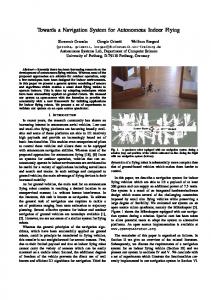
Figure 1.1: A wheel loader of the 120F model used as platform in the Autonomous Machine project.
1.2
Problem Specification
The intention of this thesis is to enable the autonomous wheel loader used in the Autonomous Machine project to navigate in a given task space. In short, the problem at hand could be divided into two distinct parts. Firstly, the system needs to be capable of localising itself in its task space using available sensors mounted on the vehicle. The second problem is to autonomously steer the wheel loader in its task space to and from given positions. In order to solve the first and the second problem, it is necessary to understand how an articulated vehicle such as a wheel loader behaves and responds in terms of steering i.e. a model needs to be derived accordingly. The localisation of the vehicle will be based on the readings of the vehicle’s internal and external sensors. Therefore, it is essential to establish models of the sensors in terms of errors and noise. Another concern is how to, with respect to errors and noise, combine the information provided by the sensor readings. Finally, steering the vehicle requires a stable and accurate control law, but also a way to represent and communicate the intended drive path.
2
Chapter 1: Introduction
1.3
Objectives
The main objective of this thesis is to conceptually demonstrate the possibility of utilising an autonomous wheel loader for the purpose of conducting a simple and repetitive work task at a production site. The targeted production site in the Autonomous Machine project is an asphalt plant. Material rehandling is the simplest and most repetitive task found at such site; gravel or similar materials is stocked at the site and where a wheel loader is utilised for the purpose of transporting the material from the stock into the production. In the case of the asphalt plant the different materials are unloaded in pockets leading to a conveyor belt feeding the plant. The motivation of the main objective, and thus this Master’s Thesis, is given as follows. A human driver becomes tired and unfocused by performing the same task for the duration of an entire shift. Two consequences arise; a tired driver is potentially dangerous and could cause lethal accidents or serve injuries; the second consequence is decreased productivity. Another motivation is the ability of an autonomous vehicle to always drive in an economical way if the situation allows it, which could be overlooked by an unfocused driver.
1.4
Safety
The vehicle is assumed to be operating in an enclosed and secured area. No humans will be present in the vicinity of the autonomous vehicle nor in its task space during autonomous operation. A wireless industrial classified safety stop has been installed in the vehicle allowing the responsible operator to shut it down, at shutdown the parking brake is automatically activated bringing the vehicle to a halt. All personnel involved in the development of this autonomous vehicle have been educated and certified accordingly for operating wheel loaders.
1.5
Delimitations
The vehicle’s task space is assumed to be moderately planar, as a consequence only planar motion will be treated. Trajectory drive paths are calculated or stored in a strategic high level software, and thus no such planning will be conducted in the following work. Furthermore, obstacles located in the task space is assumed to be static. Obstacle avoidance will therefore not be a subject of this thesis.
3
Chapter 1: Introduction
1.6
Thesis Outline
This section is intended to give a brief overview of the contents found in the chapters constituting this Master’s Thesis report. The coordinate systems used throughout the work presented in this Master’s Thesis, are defined in the brief chapter 2. Chapter 3 gives a study of the internal and external sensors mounted on the vehicle. The study includes the modelling of the sensors and a discussion regarding the involved measurement errors. Chapter 4 starts with a study of related work regarding the modelling of articulated vehicles. The study tries to outline the main aspects to consider during the modelling process. Thereafter a kinematic model is derived based on the findings in the previous study. In chapter 5 the reader is introduced to the concept of multisensor systems and sensor fusion with Kalman filters, both the classical linear Kalman filter and the extended Kalman filter are presented. A short review of another common extension is given, namely the unscented Kalman Þlter. The chapter ends with an overview of different implementation methods and schemes. Chapter 6 continues the report by applying previously discussed technique of sensor fusion to the problem of localising the vehicle in its task space. Thereafter the second problem of steering the vehicle is attended in chapter 7. The chapter does also describe other aspects regarding the vehicle’s control. The design and work of integrating the developed solution into the existing system architecture is described in chapter 8, an description of the implemented communication interface is also given. Chapter 9 finalises the report by discussing the findings and results made through the work of this thesis.
1.7
Related Work
Autonomous vehicles have traditionally been a subject of military usage. However, as in the case of many technologies they emerge from the military sector into civilian applications as the price of the technology gets more affordable. Autonomous vehicles are complex systems requiring computational power and often equipped with a wide variety of sensors. The rapid progress of computers becoming smaller, more powerful and affordable enhances the possibility to develop autonomous systems without a military founding. Regarding sensors, the technology of microelectromechanical systems (MEMS) revolutionised sensors, both regarding their price and size. Today rather advanced sensors such as accelerometers and gyros could be found in cars, mobile telephones and video gaming devices.
4
Chapter 1: Introduction
The term autonomous is often interchanged with and equalled to the term unmanned. The latter term refers only to a vessel that carries no human operator, hence it by definition could be remotely operated by a human. In contrary, an autonomous vehicle operates without a human operator’s intervention.
1.7.1
Autonomous Ground Vehicles
One of the earliest designs of a fully autonomous ground vehicle (AGV) was the Autonomous Land Vehicle In a Neural Network (ALVINN) developed 1993 at the Carnegie Mellon University. The concept was based on learning an artificial neural network (ANN) to follow a road. The road was sensed with an image array constituted by 30 times 32 pixels. The system successfully drove 145 kilometres without human assistance, and is capable of driving on both dirt roads and paved roads with multiple lanes. The probably most recognised AGVs today are the participators of the DARPA Grand Challenge held in 2004 and 2005, and the DARPA Urban Challenge held in 2007. In the latest Grand Challenge, an off-road course stretching over 210 kilometres was the subject of autonomous driving with a time limit of 10 hours. The winning team from Stanford University completed the course in just under 7 hours [1]. The course was completed by 5 of the 23 participating teams, in the first challenge non of the 15 vehicles managed to complete the course. The Urban Challenge featured a 96 kilometre long urban course to be completed within 6 hours, won by the Carnegie Mellon University completing the course in a little over 4 hours. The participating vehicles are standard cars retrofitted with computers and sensors. Typical sensors are Global Positioning System (GPS) receivers, laser rangers (LIDAR), cameras, microwave radar and inertial measurement units (IMU). The large amount of data produced by the vehicles’ sensor systems put high demands on the software architecture; emphasis is on high efficiency and configurability. The high complexity of the involved control and optimisation problems led to the usage of adaptable and learning algorithms. An interesting project, and maybe a little more related, known as Autonomous Navigation for Forest Machines is held as a part of the research conducted at the Umeå University [2]. The project’s purpose is the design and development of algorithms and techniques intended for the navigation of autonomous vehicles in off-road environments. A forest machine has successfully been used for autonomously drive along previously learnt paths. The vehicle is able to localise itself by using GPS in conjunction with laser ranging and odometry.
5
Chapter 1: Introduction
1.7.2
Autonomous Mining Equipment
One established actor providing autonomous vehicle’s for the use in the underground mining industry is Sandvik’s AutoMine system [28]. There are several benefits of autonomous vehicle’s in the mining industry. First of all it increases the safety and improves the working conditions of the personnel by removing them from the hazardous environment of an underground mine. The more economical benefits are, among others, stated as increased productivity and lower maintenance cost. The system is not fully autonomous since the bucket load sequence is tele-operated by a human. However, one human operator is capable of controlling a number of vehicles since they take turns loading their buckets. The communication is managed over a common wireless local area network with added realtime features. There are several publications related to the autonomous loaders used in underground mines, especially regarding the modelling of such vehicles. Due to their similarity to a wheel loader; a more in depth related work study is given in chapter 4 treating the modelling of the autonomous wheel loader.
1.8
Platform
The selected platform for the autonomous wheel loader is conventional wheel loader of the 120F model; a model belonging to the midsize wheel loaders offered by Volvo CE. With a weight of 20 ton it is capable of lifting some 6 to 7 ton in normal operation and is typically used in applications involving material rehandling. A ruggedised industrial computer, a PIP8 manufactured by MPL AG, featuring a realtime software environment is used for interfacing the vehicle’s different functions and sensors. The sensors are interfaced via RS232 and by the PIP8’s analogue-to-digital converters (ADC). The realtime environment, known as xPC Target, is capable of running compiled Simulink models in realtime. The models are developed in the standard Simulink environment and then compiled through C to a single file that is downloaded to the PIP8 computer. The hydraulic functions powering the actuator and the articulated steering are controlled by the PIP8’s digital-to-analogue converters (DAC) via an electrical servo system. The throttle and the brake system is controlled in a similar manner. Utility functions with on-off characteristics are controlled by general purpose input/output (GPIO) ports. Besides the DAC and the GPIO interface, the PIP8 is connected to the vehicle’s Controller Area Network (CAN) bus. At the current stage the CAN bus is mostly used for supervision purposes.
6
Chapter 1: Introduction
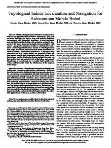
An additional computer is utilised for non-realtime tasks denoted as the high level strategic software. The high level software is developed in parallel with this thesis as a separate thesis [3]. The main responsibility of the high level software is to coordinate and command the vehicle accordingly to fulfil the current objective, and provide an graphical user interface (GUI). This computer is connected to the PIP8 computer through a standard Ethernet connection. LIDAR
Vision Algorithms
Strategic Software
Sensors
GUI
Realtime System
Vehicle Hardware
Figure 1.2: An overview of the platform hardware. A third computer dedicated to the execution of vision algorithms on the data gathered from a SICK MLS291 laser ranger (LIDAR), mounted with a servo on the cab’s roof edge, was added to the hardware architecture during the timeline of this thesis. The vision algorithms are able to detect piles and other objects that the vehicle autonomously needs to interact with. The algorithms are developed by the Örebro University as a part of their research in the field of autonomous vehicles. Interaction with the vision algorithms are conducted by the high level software over Ethernet, utilising a TCP/IP interface. The interface delivers a vector relative the vehicle to the found objects.
7
Chapter 2
Coordinate Systems 2.1
Local Planar Frame
Commonly positions are given in geodetic coordinates comprised by latitude, longitude and altitude, where the Earth is approximated by an ellipsoid. A widely known such system is the World Geodetic System 1984 (WGS84) used by for an instance the Global Positioning System (GPS). However, since the vehicle is intended to just travel on a relative small geographical region, rendering the effect of the Earth’s curvature rather insignificant, it is feasible to approximate that region with a planar system. The planar system is given by the tangental plane to the Earth’s surface fixed to a reference point located in the region of interest. N (north) U (up)
E (east)
Figure 2.1: Illustration of the local tangental plane and its Cartesian coordinate system.
8
Chapter 2: Coordinate Systems
The transformation from longitude λ and latitude φ in the geodetic coordinate system to the eastward E and northward N coordinates in the local tangental plane are done in accordance with
E = Re ∆λcos(φ) N = Re ∆φ where Re is the Earth’s radius at the current latitude, and
∆λ = λ − λref erence ∆φ = φ − φref erence .
2.2
Vehicle Body Fixed Frame
The vehicle body fixed frame is a coordinate system having its origin in the middle point of the vehicle’s rear wheel axle. The reason why the rear body of the wheel loader was selected to host the vehicle body frame was simply due to the fact that all vital sensors are located there. The x-axis points in the forward direction denoted as the longitudinal axis. Perpendicular to the x-axis, the y-axis points to the left. The y-axis is also referred to as the lateral axis. Lastly the z-axis is specified to point skywards, which completes the right hand system. x ˆ
yˆ
zˆ
Figure 2.2: The vehicle body fixed coordinate system.
9
Chapter 3
Sensors In this section the reader will be introduced to the sensors installed on the vehicle. Sensors that do not concern the vehicle’s translational movement are, for the cause of simplicity and comprehensibility, omitted.
3.1
Sensor Measurement Model
It is crucial to understand what a particular sensor actually measures in order to utilise the obtained data in an appropriate manner. The measurement of a physical quantity is not a direct reflection of its true value since it contains errors of different characteristics. In the simplified measurement model (3.1.1) of the arbitrary physical quantity x, errors such as scalar error kx , bias error bx , normal distributed white noise ηx and quantisation error ∆x are taken into account. In reality other errors exist, but they will be assumed to be rather small in comparison to the errors already accounted for in the model and are therefore neglected.
x ˜ = (1 + k)x + bx + ηx + ∆x
3.2
(3.1.1)
Odometry Sensors
In order to perform simple odometry one needs to measure the articulation angle and the linear velocity of the vehicle as shown later in chapter 4. The two sensors described below were mounted prior the work of this thesis.
10
Chapter 3: Sensors
3.2.1
Articulation Angle Sensor
The sensor measuring the articulation angle is a linear potentiometer working in the range 0.5 to 4.5 volts, where 0.5 volt corresponds to a -60 degrees angle and 4.5 volt to 60 degrees. However, only a limited span of the available range is utilised since the mechanical range of the articulation angle is between -36 to 36 degrees. The given model below models the sensor in terms of degrees
ϕ˜ = ϕ + bϕ + ηϕ
(3.2.1)
where the bias error bϕ has been experimentally determined to 0.3 degrees and the noise ηϕ has been approximated to have one standard deviation of 0.03 degrees.
3.2.2
Rotary Encoder
An encoder wheel together with two inductive sensors, mounted on the centre drive shaft delivering power to the front and rear wheel axles, are used to calculate the angular velocity of the wheels. The output from the inductive sensors are counted in a register, where one least significant bit (LSB) correlates to a drive shaft rotation of 0.148 radians. A 18.37:1 drive shaft to wheel ratio gives a wheel rotation of 0.008 radians per LSB. The wheel angular velocity derived from the encoder, by differentiation and averaging, is modelled by
ω ˜ = (1 + kω )ω + ∆ω
(3.2.2)
where kω and ∆ω denote a scalar error and a quantisation error, respectively. Regarding the scalar error kω , it is believed to be rather small due to excessive calibrations. The quantisation error ∆ω has been approximated to ±0.05 radians per second. The vehicle’s linear velocity is calculated in accordance with
v˜ = R˜ ω
(3.2.3)
where R denotes the average wheel radius. However, the wheel radius will change over time depending on tyre wear down and the current load of the the wheel loader. Therefore it would be beneficial to estimate the radius with for an instance a Kalman filter (KF), which will be further investigated in chapter 6.
11
Chapter 3: Sensors
3.3
Inertial Measurement Unit
The Xsens MTi-G inertial measurement unit (IMU) is capable of outputting raw, calibrated and processed sensor measurements, where the latter is processed by an extended Kalman filter (EKF) in the unit’s internal digital signal processor (DSP). It also features a built-in Global Positioning System (GPS) receiver. In the calibrated output mode the raw readings from the 16-bit ADC are converted to physical quantities and where calibration with, among others, respect to temperature, bias, sensitivity and misalignment1 has been accounted for. Important to say is that no filtering or other temporal processing has been applied to the calibrated measurements. The calibrated output contains the measurements of acceleration, angular velocity and magnetic field strength2 , in six degrees of freedom. Appendix F provides the sensor specifications. An acceleration measurement is given by
a ˜ = a + ηa
(3.3.1)
where only the noise ηa has been considered as an error. Even though the gyroscopes measuring angular velocities are carefully calibrated, they drift i.e. there will always be an apparent angular velocity in their measurements. For that reason the gyroscope model will contain a bias error denoted as bψ . The noise ηψ needs to be considered as well, thus the resulting model is ψ˜ = ψ + bψ + ηψ .
(3.3.2)
Lastly the magnetometer measurements are modelled by β˜ = β + bβ + ηβ
(3.3.3)
where the bias bβ could be an effect of, for an instance, permanent magnets and ferromagnetic materials in the vicinity of the IMU. Even though the IMU provides a sophisticated sensor fusion by its internal EKF serve difficulties regarding drift in the heading estimation has been experienced. An analysis of the magnetometer data shows major disturbances during turning, which is caused by the nature of a wheel loader’s mechanical arrangement. The movement of the substantial masses of steel seems to skew the Earth’s magnetic field to a large extent. Different EKF configurations and physical placements on the wheel loader itself have not resolved the problem to a satisfactory level. The best performance was achieved with the configurations not accounting the magnetometers. However, then the unit looses an observer of the heading, making the GPS the only available source of heading corrections. As a consequence 1 Misalignment 2 Normalised
relative the sensor housing. to the Earth’s magnetic field strength.
12
Chapter 3: Sensors
the heading estimate became a subject to a serve drift during standstills. For that reason it was decided that the calibrated sensor output and the GPS output will be the only outputs utilised from the IMU for localisation purposes i.e. its internal EKF will not be used. It was believed that a sensor fusion utilising more sensors than available to the IMU would be capable of achieving a more satisfactory performance, which is further explained in chapter 5.
3.4
Global Positioning System
The Global Positioning System (GPS) is a Global Navigation Satellite System (GNSS) used in a vast range of both military and civilian applications where localisation and time synchronisation is essential. In short, the GPS consist of a set of satellites continuously transmitting a radio signal containing a time stamp of the transmission and the orbital position of the satellite in question. A GPS receiver is thereby able to locate itself by calculating the received signals’ travel times and interpret the times as imaginary spheres originating from the corresponding satellites. The intersections of those spheres define the possible positions of the receiver’s antenna. Figure 3.1 illustrates the principle of GPS positioning, where a, b, c denotes three visible satellites and r the position of the receiver antenna.
b
a
c
r Figure 3.1: Illustration of the conceptual idea of GPS positioning. The GPS receiver used in this particular thesis is capable to give measurement updates at a rate of 4 Hz and features 50 channels. It is also prepared for the GALILEO system - a future alternative to the GPS. The types of measurements provided by the receiver are as follows, firstly the position measurement " # ˜ E ˜ N
=
" # E N
+ ηp
(3.4.1)
˜ and N ˜ are the measured east and north positions on the local tangent plane frame, respecwhere E tively. Regarding the positional noise ηp it is specified as 2.5 meters circular error probability (CEP). That is, that 50% of the measurement samples are located within a circle of 2.5 meters radius. The standard deviation is calculated by 13
Chapter 3: Sensors
σp =
1.2CEP √ 2
(3.4.2)
which in this particular case gives a standard deviation σp of roughly 2 meters applicable to both the east and north position measurements. The used GPS receiver compares the apparent carrier frequencies of the satellites with a local oscillator and can thereby calculate the Doppler shifts. The knowledge of the Doppler shifts, in conjunction with the quite small wavelength of the GPS signals, it is possible to determine the receiver’s velocity with a rather high accuracy. In contrary, GPS receivers of an older model or receivers with limited computational capabilities are often incapable of utilising this technique [4]. Instead the velocity is a derivative of the current and previous positions, yielding a very coarse accuracy. The measured velocities in the tangent plane are given in the eastward direction v˜E and the northbound direction v˜N in accordance with "
v˜E
v˜N
#
" =
vE vN
# + ηv .
(3.4.3)
A significant advantage of accurate GPS velocity measurements is the possibility to calculate the heading with rather high accuracy, even in low speeds. If no vehicle side slip occurs the heading could simply be calculated by v˜N θ˜GP S = arctan( ). v˜E
(3.4.4)
Trials have shown that the GPS heading is reliable in speeds above 1.5 meters per second.
3.4.1
Dilution of Precision
The additional loss in precision due to the GPS satellites’ relative geometrical configuration is reflected through certain dilution of precision (DOP) measurements. Generally speaking, the highest precision is obtained when the available satellites are evenly distributed on the sky, hence a minimal DOP value will be obtained. In contrary, a high DOP value will be obtained if the satellites are clustered together. Another factor having a major impact on the DOP measurements are obstacles blocking or reflecting the satellite signals. There are several independent DOP measurements characterising the current precision that could be expected. The GPS receiver used in this thesis gives for every update a horizontal dilution of precision (HDOP) and a vertical dilution of precision (VDOP). Regarding the positioning in the plane, the HDOP measurements can be used for detecting invalid GPS positions.
14
Chapter 3: Sensors
3.4.2
Differential GPS
The fundamental concept behind a Differential Global Positioning System (DGPS) is the fact that receivers in the same geographical region experiences roughly the same atmospheric interference. Furthermore, receivers using the same set of satellites will be the subject of the same satellite clock errors affecting the positioning precision. Therefore it would be beneficial if one receiver could be utilised to determine the error in its region, an error that is forwarded to other user receivers in the region making them able to correct their measurements. For an instance, a common method is to mount a receiver at a fixed known position and broadcast the calculated error over radio. Even though the atmospherical interference is approximately the same, it will vary. As a consequence the correction accuracy will degrade with the user’s distance from the reference transceiver. Another problem, affecting the accuracy negatively, arises if a user does not see the same set of satellites used by the reference.
15
Chapter 4
Vehicle Modelling A model describing how a vehicle’s position and other important vehicle parameters evolve over time is an essential feature in a successful autonomous navigation system. Even though a wheel loader has many attributes to model this report will focus on modelling the traversing motion of a wheel loader in its task space. In other words the modelling of the wheel loader’s actuator will not be covered.
4.1
Related Work
The following section summarises selected work described in literature regarding the modelling of articulated vehicles. The reader should be aware of that a commonly appearing vehicle in such literature is the Load-Haul-Dump (LHD) vehicle - a heavy equipment vehicle moving ore from the rock face to a dump point in underground mining facilities. Even though the LHD operates in a different environment than a wheel loader; the two vehicles are more or less identical in the modelling point of view. Regarding autonomous navigation of articulated vehicles there has been some debate in literature about whether lateral slip should be neglected or not in the model [5]. The latter requires the vehicle’s dynamics to be accounted for in contrary to the former where only the vehicle’s kinematic geometry is sufficient for deriving a model. Scheding et al. [6] compares different navigation systems of an autonomous LHD vehicle. It was concluded that the vehicle slipped to such an extent, especially during cornering, that a system only utilising dead reckoning based on a non-slip model through odometer data and articulation angle simply failed. The effect of excluding the slip causes the model to overestimate the vehicle’s turning rate. As a consequence the model error needs to be corrected continuously. The non-model was derived from rigid body and rolling motion constrains and is stated by
16
Chapter 4: Vehicle Modelling
x˙ = V cos(θ) y˙ = V sin(θ) θ˙ = V
(4.1.1)
tan( ϕ2 ) L
where x, y and θ denotes the vehicle position and orientation relative to a global frame. V is the vehicle’s linear velocity, ϕ the articulation angle between the two body halves and L is the length from a body’s wheel axle and the articulation hinge1 . The more successful system involved a model explicitly accounting for slip, where the slip was estimated with inertial sensors and an Extended Kalman Filter (EKF) since it is not directly observable. It was found that modelling the slip accurately was extremely difficult since it depended on numerous of other parameters in a highly nonlinear manner. The model accounting for slip is given by
x˙ = V cos(α + θ) y˙ = V sin(α + θ) θ˙ = V
(4.1.2)
sin(β − α + ϕ) L cos(β) − ϕ˙ L(cos(β) + cos(β + ϕ) L(cos(β) + cos(β + ϕ)
where the new variables α and β denotes the slip angles of the wheel pairs on respective axle. A slip angle is defined as the angle between the kinematically indicated velocity vector and the true velocity vector of that particular body section. Observe the utilisation of the first derivative of the articulation angle ϕ. In the approach purposed by Dragt et al. [7] Lagrangian dynamics is used for the purpose of modelling a LHD vehicle. The vehicle model includes tyre models in an attempt to account for basic tyre dynamics such as cornering slip. However, their work was only conducted to the extent of limited simulations i.e. no comparisons were made with the respect to a real vehicle. One difficulty experienced in their work was the missing data on tyre parameters. Altafini [8] derives a non-slip model and states that the dynamic effects could be neglected since the vehicle in question operates in slow speeds. The derived non-slip model accounts for vehicle specific features such as lengths between wheel axles and the articulation hinge. Compared to the previous presented non-slip model (4.1.1) it also takes the articulation angular rate in account when computing the vehicle’s rate of change in orientation. In fact, the model derived by Altafini [8] is very similar to the dynamic model purposed by Scheding et al. [6]. The difference is the two additional slip angles found in the latter model. The model derived by Altafini [8] is given by 1 The
model assumes that the vehicle’s axles are located on the same distance to the articulation joint.
17
Chapter 4: Vehicle Modelling
x˙ i = V cos(θi ) y˙ i = V sin(θi )
(4.1.3)
sin(ϕ) L2 − ϕ˙ L2 + L1 cos(ϕ) L2 + L1 cos(ϕ) sin(ϕ) L2 cos(ϕ) θ˙2 = V + ϕ˙ L2 + L1 cos(ϕ) L1 + L1 cos(ϕ) θ˙1 = V
where i = {1, 2} and the indexes of x, y, L and θ refer to one of the two body halves. In the work by Corke et al. [9] the model (4.1.3) by Altafini [8], referred to as the full kinematic model, is adopted and compared to the simpler kinematic model (4.1.1) used in Scheding et al. [6]. It is shown both experimentally and theoretically that the simpler model has a significant bigger error in orientation than the full kinematic model (4.1.3), especially at lower speeds. The trials were carried out on a full size LHD using a set of IMUs as references.
4.2
Wheel Slip
The literature previously studied indicated the importance of accounting for wheel slip. Therefore a short review of both longitudinal and lateral slip will be given in this section.
4.2.1
Longitudinal Slip
The longitudinal wheel slip s is commonly defined as the difference between wheel circumference velocity and the vehicle’s longitudinal ground velocity in accordance with
s=
vx − ωre vx
(4.2.1)
where vx is the vehicle’s longitudinal velocity and ωre the angular velocity of the wheel multiplied with the wheel’s effective radius, the latter is also known as the unloaded radius. Longitudinal slip will occur if the friction force between the wheel and the ground surface is exceeded by the force induced by the torque applied to the wheel. For small values the relationship between slip and the utilised friction coefficient µ = Fx /Fz , where Fx is the friction force and Fz the wheel normal force in a wheel hub centred coordinate system, is linearly given by µ = ks. On solid surfaces the wheel normal force Fz could be approximated by the normal force N . However, in off-road conditions the ground is deformed by the wheel, and as a consequence the wheel normal force Fz is shifted towards the direction of motion.
18
Chapter 4: Vehicle Modelling
4.2.2
Lateral Slip
A vehicle negotiating a turn is the subject of an angular velocity changing its orientation and an lateral acceleration directed towards the instantaneous centre of rotation, thus a side force Fy will arise in the contact surface between the wheel and the ground surface. Consequently the side force Fy induces an lateral slip defined, more precise than previously, as the angle α between the wheel’s rotational direction and the velocity vector of the ground contact point i.e. the true ground velocity. For small values of lateral slip α, the side force Fy could linearly be related to α through a wheel specific parameter known as the cornering stiffness C. That is, Fy = Cα. v
α
ωre
Figure 4.1: Illustration of the lateral slip angle and the related velocity vectors.
19
Chapter 4: Vehicle Modelling
4.3
Kinematic Model
In the following section the full kinematic model (4.1.3) described in [8] will be derived. According to [9] this particular kinematic model seems to be the more accurate one of the two discussed non-slip models, consequently the simpler kinematic model is neglected in favour of the full kinematic model. Even though the selected model may not be as accurate as the models accounting for slip, it is of a much lower complexity since modelling the slip is a non-trivial problem [6]. However, if it is later concluded that lateral slip must be accounted for, it will be rather straightforward to adapt the model due to its similarity with the slip model (4.1.2). P2 (x2 , y2 )
L2 ϕ θ2 L1 yˆ
P1 (x1 , y1 )
x ˆ
θ1
Figure 4.2: Schematic illustration of an articulated vehicle. Referring to figure 4.2, the geometrical relationship between the two wheel axle midpoints P1 and P2 located on the distances L1 and L2 from the articulation joint is given by the two following equations
x2 = x1 + L1 cos(θ1 ) + L2 cos(θ2 )
(4.3.1)
y2 = y1 + L1 sin(θ1 ) + L2 sin(θ2 ) and the relationship between the angles by
ϕ , θ2 − θ1
(4.3.2)
where θ1 and θ2 are the orientation angles of respective body halve and ϕ is the articulation angle. The motion of an axle midpoint Pi is described by
x˙ i = vi cos(θi ) y˙ i = vi sin(θi )
20
(4.3.3)
Chapter 4: Vehicle Modelling
where i = {1, 2} and vi is the velocity vector associated to that midpoint during motion. The assumption of no lateral slip during motion implies that there are no velocity components perpendicular to the two body halves, which is stated by
x˙ 1 sin(θ1 ) − y˙ 1 cos(θ1 ) = 0
(4.3.4)
x˙ 2 sin(θ2 ) − y˙ 2 cos(θ2 ) = 0. Differentiating (4.3.1) with respect to time and substituting the obtained velocity components with (4.3.3) and (4.3.4) will after simplification using (4.3.2) and the angle sum and difference identities for sine and cosine result in θ˙1 = v1
sin(ϕ) L2 − ϕ˙ . L2 + L1 cos(ϕ) L2 + L1 cos(ϕ)
(4.3.5)
Using same the methodology but solving for θ2 gives θ˙2 = v1
L1 cos(ϕ) sin(ϕ) + ϕ˙ . L2 + L1 cos(ϕ) L2 + L1 cos(ϕ)
(4.3.6)
The complete calculations of how to derive (4.3.5) and (4.3.6) from the given equations are avaiable in appendix A. Let, for simplicity, the set (x˙ 1 , y˙ 1 , θ˙1 ) refer to the rear body halve and the set (x˙ 2 , y˙ 2 , θ˙2 ) to the front body halve. Then the rear body could be described by the following kinematic model
x˙ y˙ = θ˙
cos(θ)
0
sin(θ)
0
sin(ϕ) L2 + L1 cos(ϕ)
−
L2 L2 + L1 cos(ϕ)
v ϕ˙
(4.3.7)
and the front body by
x˙ y˙ = θ˙
cos(θ)
0
sin(θ)
0
sin(ϕ) L2 + L1 cos(ϕ)
L1 cos(ϕ) L2 + L1 cos(ϕ)
where v = v1 = v2 due to the assumption of no slip.
21
v ϕ˙
(4.3.8)
Chapter 4: Vehicle Modelling
4.3.1
Model Verification
The most essential aspect of the full kinematic model previously derived is the vehicle angular velocity; a physical quantity that is measured by the gyro as well. The validity of the model is thereby possible to verify by comparing the angular velocity measured by the gyro with the value obtained from the model. The concept of a soft sensor was applied to the model. Even though the implementation in figure 4.3 seems rather straight forward, there are some issues to account for. It is not feasible to differentiate the articulation angle ϕ due to noise. For that particular reason a second order Infinite Impulse Response (IIR) low-pass filter has been added prior the differentiator. The low-pass filter’s cutoff frequency needs to be low enough to yield an acceptable differentiation, but a too low cut-off frequency will introduce a noticeable phase lag degrading the soft sensor’s performance. A cut-off frequency of 1 Hz and a damping of
√1 2
where found to be appropriate.
ω ϕ
Model
ψ
δϕ δt
IIR Low-pass
Figure 4.3: A schematic description of the soft sensor based on the full kinematic model.
22
Chapter 4: Vehicle Modelling
In figure 4.4 and 4.5 the soft sensor is compared to the gyro during a manual drive at the track denoted as POND. The former figure, comparing the two angular velocities, clearly indicates a tendency of the calculated angular velocity to be overestimated. Still it must be concluded that the model reflects the behaviour of the vehicle. 30 Gyro Soft Sensor
Yaw Rate [deg/s]
20
10
0
−10
−20
−30 0
50
100
150
200 250 Time [s]
300
350
400
450
Figure 4.4: Comparison between the angular velocity as measured by the gyro and the soft sensor.
7
Absolute Error [deg/s]
6 5 4 3 2 1 0 0
50
100
150
200 250 Time [s]
300
350
400
450
Figure 4.5: The absolute error between the gyro measurement and the calculated angular velocity.
23
Chapter 5
Sensor Fusion In this chapter the reader will initially be given an introduction to multi-sensor fusion and one of the most common tool used for that particular purpose, namely the Kalman filter (KF). The chapter continues with an overview of selected KF extensions and common implementation methods.
5.1
Multisensor Systems
Sensor fusion is the technique of combining measurements from multiple sensors in a system such that the combined result is more advantageous than if the measurements were individually used. The provided advantages gained from multi-sensor fusion are; a more wider and diverse aspect of the system is measured; the robustness of the system is possible to increase by statistical methods, complementary measurements and sensor redundancy [10].
5.2
Kalman Filters
A Kalman filter estimates the state of a noisy linear dynamic system by noisy measurements that could be linear related to the system’s state. If the corrupting noise is independent, white and normal distributed with a zero mean; the KF will be a statistically optimal estimator with respect to any reasonable quadratic function of estimation error.
5.2.1
Historical Background
The first formal method of acquiring an optimal estimation from noisy measurement was the method of least squares. A method whose discovery often is credited to Carl Friedrich Gauss in the late eighteenth century (1795) at an age of eighteen. Gauss recognised that the least square method
24
Chapter 5: Sensor Fusion
was just the beginning of numerous interesting studies. However, he stated that the time was not right for these studies and must be reserved for future occasions when faster computations could be accomplished [11]. Taking a 140-year leap in history until the early years of the Second World War, Norbert Wiener was involved in a military project regarding an automatic controller aiming anti-aircraft guns based on noisy radar tracking information. The controller needed to predict the position of an airplane at the time of the arrival of the projectiles. His work lead to the formulation of the Wiener filter, that is a linear estimator of a stationary signal and is optimal in terms of the minimum mean square error. In 1958 Rudolf Emil Kalman got the idea of applying state variables to the Wiener filter. Two years later his filter, now known as the Kalman filter, was introduced to the researchers involved in the trajectory estimation and control problem of the Apollo program. In the following year of 1961 the filter was incorporated as a part of the Apollo onboard guidance system. In fact it was a modified version of the original KF called the Kalman-Schmidt filter; today known as the extended Kalman filter (EKF). The Kalman filter is said to be one of the biggest discoveries in the history of statistical estimation theory. Without it many achievements after its discovery would not have been possible. It has become a vital component in a wide variety of applications spanning from estimating the trajectory of a spacecraft, to predicting the finance market.
5.2.2
Linear Dynamic System Model
One fundamental assumption made by the KF is that the true dynamic system state, denoted as x, evolves from the time instance k − 1 to k in accordance with a noisy linear dynamic system
xk = Fk xk−1 + Gk uk + wk−1
(5.2.1)
where the different matrices and vectors are explained as follows. The state transition matrix Fk relates the state xk−1 to the proceeding state xk . Gk denotes the input matrix and relates the input vector uk to xk . The process noise wk is assumed to be normal distributed white noise with zero mean and a covariance of Qk , more formally stated as wk ∼ N (0, Qk ).
(5.2.2)
γk ∼ N (0, Γk ).
(5.2.3)
Likewise the input noise γk is given by
25
Chapter 5: Sensor Fusion
Furthermore, if an observation zk is made of the state xk , the observation is described by the observation model
zk = Hk xk + vk
(5.2.4)
where Hk is the observation matrix mapping the state space into the observation space. The observation is assumed to be perturbed by normal distributed white noise vk with zero mean and a covariance of Rk , known as the observation noise
vk ∼ N (0, Rk ).
5.2.3
(5.2.5)
Linear Kalman Filter
As previously stated the original KF assumes the underlying dynamic system to evolve in a linear manner and is for that particular reason commonly referred to as the linear Kalman filter (LKF). Algorithm A Kalman filter could be divided into two distinct phases. In the first phase, the prediction phase, the KF estimates the current state of the system based on the previous state using a given model of the system. This estimation is called the a priori state estimate since it is an estimate prior the observation of the system state. The latter is done in the second phase, the correction phase, where the current state is observed through sensor measurements. The observations are then combined with the a priori state estimate to form the a posteriori state estimate - an improved state estimation of the true system state. Prediction Equations ˆ k|k−1 and the a priori estimate Looking at the prediction phase, the a priori state estimate vector x error covariance matrix Pk|k−1 is given by
ˆ k|k−1 = Fk x ˆ k−1|k−1 + Gk uk x Pk|k−1 =
Fk Pk−1|k−1 FTk
+
Gk Γk GTk
(5.2.6) + Qk .
(5.2.7)
In this phase the KF essentially drives the state forward in accordance with the system model and input model matrices represented by Fk and Gk , respectively. Through the covariance matrices Γk and Qk , the KF is given knowledge about the noise corrupting the system state. Consequently the KF utilises this knowledge to, with the estimate error covariance matrix, reflect the uncertainty of the a priori state estimate. 26
Chapter 5: Sensor Fusion
Correction Equations ˜ k reflecting the difference between The correction phase begins with calculating the innovation1 y the actual observation zk and the predicted observation
˜ k = zk − H k x ˆ k|k−1 y
(5.2.8)
and where the innovation covariance is given by Sk = Hk Pk|k−1 HTk + Rk .
(5.2.9)
The Kalman gain Kk is a factor determining the extent of the innovation accounted for when calculating the a posteriori state estimate. The factor is determined by the relative uncertainty between the a priori state estimate and the innovation
Kk = Pk|k−1 HTk S−1 k = Pk|k−1 HTk (Hk Pk|k−1 HTk + Rk )−1 .
(5.2.10)
ˆ k|k , where the predicted state is corrected by the knowledge Lastly the a posteriori state estimate x obtained from the observation, and the a posteriori estimate error covariance Pk|k are calculated by
ˆ k|k = x ˆ k|k−1 + Kk y ˜k x
(5.2.11)
Pk|k = (I − Kk Hk )Pk|k−1
(5.2.12)
which completes the KF.
Kalman Gain In order to understand the behaviour of the filter one should consider the Kalman gain calculation stated in equation (5.2.10). When Rk approaches zero, implicating that the noise in the observation is approaching zero, the Kalman gain increases lim Kk = H−1 k .
Rk →0
(5.2.13)
As a consequence the KF converges rapidly to the observed state since it is believed to contain more accurate knowledge about the true state than the a priori state estimate. On the contrary, the opposite effect occurs when the a priori estimate error covariance Pk|k−1 approaches zero 1 Also
known as the measurement residual.
27
Chapter 5: Sensor Fusion
lim
Pk|k−1 →0
Kk = 0.
(5.2.14)
In other words the KF trust the prediction more than the observation and will act accordingly by converge slowly to the observed state. The time it takes depends on the process and input noise added at every iteration of the prediction phase, which is defined by Qk and Γk , respectively. Initialisation ˆ k−1|k−1 to the true state of the system, The initialisation of a KF is done by setting the state vector x or what the current state could be assumed to be during initialisation. The uncertainty of the initial state is reflected by adjusting the covarience matrix Pk−1|k−1 accordingly.
5.2.4
Kalman Filter Extensions
Since the world, as we know it, often practices nonlinear dynamic systems the linear KF was limited in regard of its practical real world usage. Therefore the original KF was modified accordingly to conquer the applications involving the nonlinear systems.
Extended Kalman Filter The extended Kalman filter (EKF) was the result of the inability to apply the LKF onto nonlinear systems, although the EKF resembles the LKF in many aspects. As implicated in the case of the EKF the state transition and observation models could be nonlinear functions
xk = f (xk−1 , uk ; γk ) + wk−1
(5.2.15)
zk = h(xk ; vk ).
(5.2.16)
The function f (· ) can directly be used by the EKF to compute the a priori state estimate
ˆ k|k−1 = f (ˆ x xk−1|k−1 , uk ).
(5.2.17)
However, it is not possible to apply f (· ) directly to the computations of the a priori estimate error covariance. To deal with this problem the EKF linearises f (· ) around the a posteriori state estimate ˆ k−1|k−1 of the previous time instance in accordance with x
28
Chapter 5: Sensor Fusion
∂f ∂x xˆ k−1|k−1 ∂f Gk = ∂u xˆ k−1|k−1 Fk =
(5.2.18) (5.2.19)
where the Jacobian matrices Fk and Gk contains the first-order partial derivatives of f (· ) with respect to the state x and input u vectors, respectively. The prediction phase is completed by calculating the a priori estimate error covariance Pk|k−1 = Fk Pk−1|k−1 FTk + Gk Γk GTk + Qk .
(5.2.20)
Similar to the case of f (· ) the function h(· ) is directly applied to the a priori state estimate in the purpose of calculating the innovation
˜ k = zk − h(ˆ y xk|k−1 ).
(5.2.21)
Again, in order to utilise h(· ) in the remaining equations it needs to be linearised. This time the ˆ k|k−1 as stated by linearisation takes place around the a priori state estimate x ∂h Hk = ∂x xˆ k|k−1
(5.2.22)
where Hk is the the Jacobian matrix of h(· ) with respect to the state x. Finally the correction phase is completed by
Kk = Pk|k−1 HTk (Hk Pk|k−1 HTk + Rk )−1
(5.2.23)
ˆ k|k = x ˆ k|k−1 + Kk y ˜k x
(5.2.24)
Pk|k = (I − Kk Hk )Pk|k−1
(5.2.25)
which completes the EKF as well.
29
Chapter 5: Sensor Fusion
Unscented Kalman Filter The unscented Kalman filter (UKF) is applicable to nonlinear system without the need of analytically linearising the system and measurement models as in the case of the EKF. Instead of calculating the Jacobian matrices the UKF utilises a deterministic weighted sampling method known as the unscented transform. The sample points selected, denoted as sigma points, are chosen in such way that a fixed and minimal number of points propagated through the nonlinear transform, gives an estimate of the transformed mean and covariance. The advantage of the UKF is its ability to circumvent the inaccuracy found and problems associated with the first-order linearisation used by the EKF. In Julier et. al. [12] the following aspects are described. Firstly, the linearisation is only reliable if the error propagation is approximately linear, otherwise the EKF will perform inadequately and may even in the worst-case diverge. Furthermore, the linearisation is only possible if the Jacobian matrices exist, which is not the case of system with discontinuities. For an instance, discontinuities may arise due to highly quantised sensor measurements. Lastly, the actual calculation of the Jacobian matrices could be prone to errors.
5.2.5
Implementation Methods
The Kalman filter could be utilised in many ways to fuse sensor measurement signals. In short, there are two main implementation methods; the direct method and the indirect method [13].
Direct Pre-filtering The direct pre-filtering method applies a KF to each individual signal. Thereafter an error is formed by subtracting the estimates, and lastly one of the estimates are compensated with the error. Signal A
+
Kalman Filter
−
x ˆ
+ − Signal B
Kalman Filter
Figure 5.1: Direct pre-filtering implementation scheme.
30
Chapter 5: Sensor Fusion
Direct Filtering In the direct filtering method all measured signals are directly feed into a KF as illustrated in figure 5.2. The KF utilises a full model of the system and is thereby able to estimate the system state by the provided measurement updates. A major advantage of the direct method is the ability of the KF to still conduct corrections with only one signal available, yielding a robust implementation. Signal A
x ˆ
Kalman Filter Signal B
Figure 5.2: Direct filtering implementation scheme.
Indirect Feedforward The indirect feedforward method compares the signals by subtraction prior the KF. In this method the KF utilises a sensor error model instead of a system model, in other words the KF estimates the measurement error instead of the system state. The estimated error is feedforward and removed from one of the sensor measurements, resulting in a corrected state estimate. If the system is complex in terms of modelling an indirect method could be advantageous since the sensors and their errors could be simpler to model. The implementation scheme of the indirect feedforward method is shown in the following figure 5.3. +
Signal A
− + −
x ˆ
Kalman Filter
Signal B
Figure 5.3: Indirect feedforward implementation scheme.
31
Chapter 5: Sensor Fusion
Indirect Feedback The indirect feedback method is very similar to the previous method. The difference lies within how the error estimate is utilised. In the indirect feedback method the error is actually used to correct one of the signals. As a consequence the error estimate is bounded to a finite limit, which is not the case of the indirect feedback method. Signal A
x ˆ
− Kalman Filter
+ −
Signal B
Figure 5.4: Indirect feedback implementation scheme.
32
Chapter 6
Localisation In this chapter the reader will be presented a selection of the sensor fusion solutions implemented and applied to the problem of localisation. The solutions is based on the subjects introduced and discussed in the previous chapters. In appendix C an overview is given of the two courses used in this chapter for evaluating the found solutions.
6.1
Full Model Kalman Filter
The following Kalman filter (KF) will be based on the vehicle’s kinematic equation (4.3.7) previously derived in chapter 4, hence the filter’s state will be driven forward by the odometric sensors in the prediction phase. In the correction phase the filter will be corrected by GPS measurements.
6.1.1
Model
The filter is implemented in a straightforward manner using the direct filtering implementation scheme. The scheme was selected due to its simplicity and robust features. The filter’s state vector xk is constituted by the following sate variables T
xk = [ xk yk θk vk ] .
(6.1.1)
ω R cos(θ )T k k xk xk−1 ω R sin(θ k k )T yk yk−1 = + L sin(ϕk ) ω R θk θk−1 k L + L cos(ϕ ) T − ϕ˙k L + L cos(ϕ ) T k k vk vk−1 ω R
(6.1.2)
The model is given by
k
33
Chapter 6: Localisation
where L denotes the distance between a wheel axle and the articulation hinge, and R the average wheel radius measuring approximately 0.8 meters. More concisely the model is written as
xk = f (xk−1 , uk ; γk ) + wk−1 .
(6.1.3)
where the input vector uk is constituted by the wheel angular velocity ωk , the articulation angle ϕk and the articulation angle rate ϕ˙ k T
uk = [ ωk ϕk ϕ˙ k ] .
(6.1.4)
Differentiating the model with respect to xk gives the following system Jacobian matrix Gk
Fk =
∂f ∂x xˆ k−1|k−1
1 0 0 1 = 0 0
−ωk R sin(θk )T
0
0
ωk R cos(θk )T 1
0
0
0 0 1
(6.1.5)
(6.1.6) The input Jacobian matrix Gk is obtained by differentiating the model with respect to uk in accordance with
Gk =
∂f ∂u xˆ k−1|k−1
g11 g21 = g31 0
0 0 g32 0
0
0 g33 0
g11 = R cos(θk )T g21 = R sin(θk )T sin(ϕk ) T L + L cos(ϕk ) cos(ϕk ) L2 sin(ϕk ) L sin(ϕk )2 = (ωk R − ϕ˙k + ωk R )T 2 L + L cos(ϕk ) (L + L cos(ϕk )) (L + L cos(ϕk ))2 L =− T. L + L cos(ϕk )
g31 = R g32 g33
34
(6.1.7)
Chapter 6: Localisation
The filter’s observation function h(· ) is linear and thus the observation Jacobian matrix Hk is given by
∂h Hk = ∂x xˆ k|k−1
1 0 = 0
0
0
0
1
0
0
1
0
0
0
0 0 1
(6.1.8)
and the measurement vector zk by h iT ˜k N ˜k θ˜k v˜k zk = E
(6.1.9)
where the variables E˜k and N˜k are measured by the GPS and given as a position in the local tangental plane. The orientation θ˜k is calculated from the GPS velocity components in accordance with equation (3.4.4), and v˜k as ( v˜k =
−
p
2 +v 2 v˜E ˜N
if ωk ≥ 0
p
2 v˜E
if ωk < 0
+
2 v˜N
(6.1.10)
since the GPS receiver is not able to determine if the vehicle is driving forward or reversing.
6.1.2
Covariance Matrices
System and Input Covariance The system covariance matrix Qk was initially given values by intuition, and tuned until achieving a desired filter behaviour.
0.22 0 Qk = 0
0
0
0.22
0
0
0.12
0
0
0
0
0 0 0.12
(6.1.11)
Regarding the tuning of the input covariance matrix Γk , the initial values were selected in accordance with the sensors’ noise as discussed in chapter 3.
0.082 Γk = 0 0
0 0.0012 0
35
0
0 0.12
(6.1.12)
Chapter 6: Localisation
Measurement Covariance The initial values of the measurement covariance matrix Rk where based on the performance values specified for the GPS unit. However, it was found that the GPS measurements did drive the filter too hard and for that reason the initial values where increased until a satisfactory filter performance was obtained.
7.52 0 Rk = 0 0
0
0
7.52
0
0
0.92
0
0
36
0
0 0 0.052
(6.1.13)
Chapter 6: Localisation
6.1.3
Evaluation and Performance
Position Estimation at POND In figure 6.1 the estimated path is illustrated together with the path measured by the GPS; the contribution of performing sensor fusion is quite evident when comparing the two paths. At the last lap a GPS intermission was enforced making it possible to see the consequences of the overestimation done during corners.
100
80
GPS EKF EKF (intermission)
North [m]
60
40
20
0
−20
−40 −60
−40
−20
0
20
40
60
80
East [m]
Figure 6.1: Illustration of the path estimated by the full model filter, compared to the path measured by the GPS. The final position and orientation were compared to their equivalents in a case where no GPS intermission was enforced, yielding a relative error between the two. The relative error was determined to 22.3 meters in position and 36.4 degrees in orientation.
37
Chapter 6: Localisation
6.2
Parameter Estimating Kalman Filter
The KF derived in this section will utilise the gyro mounted in the vehicle. In the aspect of position and orientation accuracy, it is essential to account for the error originating from the gyro’s bias. The affects of the gyro bias will be especially evident during GPS intermissions when no correction occurs of the estimated pose, and as a consequence the bias error will accumulate and cause the pose estimate to drift away from the true one. Another important error to account for is the one originating from changes of the wheel radius. An errornous radius will cause an overestimation or underestimation of the traversed distance and thus the pose estimate accuracy will degrade over time if no correction occurs.
6.2.1
Model
For the previously discussed reasons, a gyro bias variable bk and an average wheel radius variable Rk are added to the state vector xk , which makes the KF able to estimate and compensate for the induced errors. The resulting state vector is given by T
xk = [ xk yk θk Rk bk ] .
(6.2.1)
As shown in chapter 4, the motion of the vehicle’s two body sections could be described by the equations (4.3.7) and (4.3.8), respectively. However, in order to estimate the gyro bias; it was found reasonable to reduce the system model. The method of [14] was adapted; assuming that the vehicle’s motion could be approximated by circular paths, which is true for an articulated vehicle when the articulation angle is constant and the two body sections are of same length. The method is further explained in appendix B. Consequently, the system model is given in accordance with
k )T ωk Rk cos(θk−1 + (ψk −b )T 2 yk yk−1 ωk Rk sin(θk−1 + (ψk −bk )T )T 2 θk = θk−1 + (ψk − bk )T R R 0 k k−1 bk bk−1 0 xk
xk−1
(6.2.2)
which could be written in the more compact form
xk = f (xk−1 , uk ; γk ) + wk−1 .
38
(6.2.3)
Chapter 6: Localisation
As implicated in the model, the input vector uk is constituted by the wheel angular velocity ωk and the gyro angular velocity ψk T
uk = [ ωk ψk ] . Substituting (θk−1 −
(bk −ψk )T 2
(6.2.4)
) in the model (6.2.2) by φ gives the following system Fk and input
Gk Jacobian matrices
∂f Fk = ∂x xˆ k−1|k−1
∂f Gk = ∂u
ˆ k−1|k−1 x
1 0 = 0 0 0
1 2 2 ωk Rk sin(φ)T − 21 ωk Rk cos(φ)T 2
0
−ωk Rk sin(φ)T
ωk cos(φ)T
1
ωk Rk cos(φ)T
ωk sin(φ)T
0
1
0
0
0
1
0
0
0
0
1
Rk cos(φ)T Rk sin(φ)T = 0 0
− 12 ωk Rk sin(φ)T 2 1 2 ωk Rk
0
−T
(6.2.5)
cos(φ)T 2 . T 0 0
(6.2.6)
Regarding the observation function h(· ) it is already linear, hence its Jacobian matrix Hk is given by
∂h Hk = ∂x xˆ k|k−1
1 0 = 0 0 0
0
0
0
0
1
0
0
0
1
0
0
0
0
0
0
0
0 0 . 0 0
(6.2.7)
The measurement vector zk contains the GPS measurements in a similar manner as previously described, that is h iT ˜k N ˜k θ˜k 0 0 . zk = E
39
(6.2.8)
Chapter 6: Localisation
6.2.2
Covariance Matrices
System and Input Covariance The system covariance matrix Qk basically resembles the one previously used in the full model filter. An exception is the additional covariances reflecting the slow varying nature of the gyro drift bk and average wheel radius Rk . The parameter covariances were tuned by initially assigning them very small values, each increased with small increments until a desired filter behaviour was observed.
0.252 0 Qk = 0 0 0
0
0
0
0
0.252
0
0
0
0
0.012
0
0 2
0
0
0.0000001
0
0
0
0
0.00000012
(6.2.9)
The input covariance matrix Γk was given values reflecting the noise of the rotary encoder and the gyro.
Γk =
" 0.082 0
0
# (6.2.10)
0.0152
Measurement Covariance As in the case of the previous filter it was found that a significant higher covariance was needed regarding the GPS position measurements, hence an almost identical covariance matrix Rk was obtained.
7.52 0 Rk = 0 0 0
0
0
7.52
0
0
0.92
0
0
0
0
40
0 0 0 0 0 0 0 0 0 0
(6.2.11)
Chapter 6: Localisation
6.2.3
Evaluation and Performance
Parameter Estimations at POND The filter was initiated, for illustrative purposes, with no prior knowledge of the gyro bias bk nor the average wheel radius Rk . Figure 6.2 and 6.3 illustrates the gyro bias estimation and wheel radius estimation, respectively. As in the evaluation of the previous filter, a GPS intermission was enforced during the the last lap corresponding to the interval between 300 to 450 seconds. The intermission is observable as a flat line in the two graphs. 2 1.5 Gyro Bias [deg/s]
1 0.5 0 −0.5 −1 −1.5 −2 0
50
100
150
200 250 Time [s]
300
350
400
450
400
450
Figure 6.2: Estimation (±σ) of the gyro bias.
1.6 1.4 Wheel Radius [m]
1.2 1 0.8 0.6 0.4 0.2 0 0
50
100
150
200 250 Time [s]
300
350
Figure 6.3: Estimation (±σ) of the average wheel radius.
41
Chapter 6: Localisation
Position Estimation at POND The estimated path is illustrated in figure 6.4 together with the path measured by the GPS. A major improvement of the result was achieved compared to the full model filter during the GPS intermission. It is not evident what exactly causes the the error; the gyro bias estimation may be slightly off, both longitudinal and lateral slip may contribute to the error as well.
100
80
GPS EKF EKF (intermission)
North [m]
60
40
20
0
−20 −60
−40
−20
0
20
40
60
80
East [m]
Figure 6.4: The estimated path illustrated together with the path as measured by the GPS. The final relative error between the case illustrated in figure 6.4 above and the case of no GPS intermission was determined to 4.7 meters in position and 3.0 degrees in orientation. The driven distance during the GPS intermission was measured to 354 meters, corresponding to an average velocity of approximately 8.5 kilometres per hour.
42
Chapter 6: Localisation
Parameter Estimations at WOODS As in the previous trial the filter was initiated with no prior knowledge of the gyro bias bk and average wheel radius Rk . The gyro bias estimate is quite consistent with the previous result. Regarding the the average wheel radius estimate, it is more stable and estimated to be a little smaller than previously. The latter could possibly be the effect of longitudinal slip due to the icy conditions during the trial. 2 1.5
Gyro Bias [deg/s]
1 0.5 0 −0.5 −1 −1.5 −2 0
50
100
150
200 Time [s]
250
300
350
400
Figure 6.5: Estimation (±σ) of the gyro bias.
1.6 1.4
Wheel Radius [m]
1.2 1 0.8 0.6 0.4 0.2 0 0
50
100
150
200 Time [s]
250
300
350
400
Figure 6.6: Estimation (±σ) of the average wheel radius.
43
Chapter 6: Localisation
Position Estimation at WOODS A high precision post-processed differential GPS (DGPS) with IMU assistance where used as a true ground reference during a manual drive on the test track designated as WOODS. The DGPS system provides an accuracy of 1 centimetre when the data is post-processed [15]. The track was partly icy and covered with snow at the time. 350
300
Reference EKF
250
North [m]
200
150
100
50
0
−50
−100 −150
−100
−50
0
50
100 150 East [m]
200
250
300
350
400
Figure 6.7: Illustration of the estimated path in comparison with a true ground reference. In figure 6.7 the positional error, calculated as the Euclidian distance, over time is illustrated together with the horizontal dilution of precision (HDOP). As could be observed, there are a vague correlation between the two. Regarding the HDOP value it is somewhat higher in the interval between 100 to 250 seconds. This agrees with the track’s terrain; the track is flanked with dense growing high trees during that particular interval, blocking the GPS antenna’s field of view.
44
Chapter 6: Localisation
2.5 Position Error Horizontal DOP
Position Error [m] / HDOP
2
1.5
1
0.5
0 0
50
100
150
200 Time [s]
250
300
350
400
Figure 6.8: The positional error illustrated together with the horizontal dilution of precision. The absolute orientation error is illustrated in figure 6.9 below. A rather evident increase of the error could be seen in the previously discussed time interval. The three peaks are an effect of the orientation modulus, thus no true errors. 5 4.5
Orientation Error [deg]
4 3.5 3 2.5 2 1.5 1 0.5 0 0
50
100
150
200 Time [s]
250
300
350
Figure 6.9: The absolute orientation error illustrated.
45
400
Chapter 6: Localisation
6.3
Slip Estimating Kalman Filter
The slip estimating method illustrated and described in Scheding et al. [6] was implemented and tested with limited success. The main problem encountered was the tuning of the covariances regarding the lateral slip state variables. It is indeed a nontrivial problem to estimate slip as stated in [6]. Instead a different approach to the problem of slip estimation was adopted. Inspired by the methods outlined in Bevly et al. [16–18], the following described solution was found.
6.3.1
Model
As previously discussed in chapter 3 the used GPS provides measurements of the vehicle’s velocity components with a rather high accuracy. In the two dimensional plane the accuracy is down to a standard deviation of 5 cm per second. It has been shown in [16–18] that the lateral slip angle β can be estimated by comparing the orientation θGP S derived from the GPS velocity components to the orientation θGyro calculated by integrating a gyro. The concept is illustrated in figure 6.10 below. V0
V β θGyro P
θGP S
Figure 6.10: Illustration of the difference between the integrated gyro orientation θGyro and the orientation θGP S derived from GPS velocity components. The solution adopted utilises an linear Kalman filter working in two modes. In the first mode the gyro bias bk is estimated by updating the filter’s orientation state variable θk with the GPS orientation θGP S . In the second mode the GPS update of the KF is stopped, hence the orientation θk will be calculated by integrating the gyro measurements ψk , which is the filter’s only input, compensated by the gyro bias bk . In both modes the lateral slip state variable βk is updated with the difference between the orientation θk and the GPS orientation θGP S . The mode transition is conducted if the vehicle’s angular velocity is above a certain threshold indicating that the vehicle is initiating a turn. Alternatively the articulation angle could be observed, in conjunction with the angular velocity, to increase the certainty of the turn indication. The complete KF is simply described in state space
46
Chapter 6: Localisation
form as 1 βk = 0 0 bk
θk
0 1 0
T 0 βk−1 + 0 ψk . 0 bk−1 1
−T
θk−1
(6.3.1)
˜ k is in accordance with Regarding the KF update phase the innovation y
θGP S
θk
˜k = y θGP S − θk − Hk βk bk 0
(6.3.2)
where the observation matrix Hk in the first mode is given by
Hk = [ 1 1 0 ]
(6.3.3)
Hk = [ 0 1 0 ].
(6.3.4)
and in the second mode by
6.3.2
Covariance Matrices
System and Input Covariance The system covariance matrix Qk was simply tuned by intuition. For simplicity no covariance input matrix Γk was used, instead the uncertainty of the gyro input is considered to be a part of the model uncertainty reflected by the system covariance matrix.
0.12 Qk = 0 0
0
0
0.12
0
0
47
0.000000001
2
(6.3.5)
Chapter 6: Localisation
Measurement Covariance In a sense the GPS orientation θGP S measurement is considered to be the true travelling direction of the vehicle, hence it was found necessary to let the GPS orientation have a rather high influence on the filter’s state. Consequently a much lower covariance was used than previously. The difference formed by the subtraction between the GPS orientation θGP S and the current orientation estimate θk resulted in a very noisy measurement, which is reflected by its given covariance in the measurement covariance matrix Rk . The final value was found by increment the covariance until a satisfactory behaviour was observed for lateral slip estimate βk .
Rk =
6.3.3
" 0.12 0
0
# (6.3.6)
0.82
Evaluation and Performance
Slip estimation at POND In figure 6.11 the estimated lateral body slip βk is compared with the measured articulation angle ϕk during a manual drive at the POND course. A constant velocity of 10 kilometres per hour was tried to be held during the drive. The vehicle’s body slip seems to be rather consistent during the three laps. 30
Body Slip [deg] / Articulation Angle [deg]
Articulation Angle Body Slip 20
10
0
−10
−20
−30
0
50
100
150
200
250
300
350
400
450
TIme [s]
Figure 6.11: Illustration of the estimated lateral body slip together with the articulation angle.
48
Chapter 7
Control 7.1
Vehicle Control
In this section, the reader will be given an overview of the regulators controlling the different physical aspects of the vehicle. The regulators controlling the hydraulic functions and the brake were developed prior this thesis. This thesis contributed with the development of a simple, yet effective, speed regulator.
7.1.1
Hydraulic Functions
The articulation hinge and the actuator’s lift and tilt functions are powered by hydraulic pistons, where the flow of hydraulic fluid is controlled by electrical flow valves. Position control is achieved by common proportional-integral (PI) regulators using the feedback from angle sensors mounted in each mechanical joint. Prior the PI regulators a simple-moving-average (SMA) is calculated for each angle measured. The sampling is done at 500 Hz, and the regulators are executed in 50 Hz.
7.1.2
Speed and Brake
In short, the brake regulator tries to estimate the needed brake pressure in order to lower the speed to a certain set-point within a given distance. However, no appropriate model has been derived for the vehicle’s brake system, and thus the successfulness of the regulator is limited due to the complexity of the problem.
49
Chapter 7: Control
Since there was no actual speed regulator prior this thesis; a velocity based proportional controller was implemented. The regulator controls the engine throttle Tk given a velocity set-point vspt and a velocity feedback vk . That is,
Tk = Tk−1 + P (vspt − vk ).
(7.1.1)
In figure 7.1 the result of a simple trial conducted on a flat surface is illustrated together with the given setpoint of 2.5 meter per second. The speed regulator’s performance could be further improved, for an instance its response is quite slow. However, its performance has been determined to suffice for the application at hand. 3.5
3
Setpoint Velocity
Velocity [m/s]
2.5
2
1.5
1
0.5
0 0
10
20
30
40
50
60
70
Time [s]
Figure 7.1: The velocity measured by the rotary encoder illustrated together with the given setpoint.
50
Chapter 7: Control
7.2
Navigation Control
The main objective of the navigational control is to steer the vehicle to given positions in its task space utilising the positioning information provided by the sensor fusion described in chapter 6. How the navigational control is interfaced and integrated are further described in chapter 8.
7.2.1
Path Representation
The path which the vehicle is intended to autonomously drive is calculated by a circle spline algorithm or loaded from a database located at a higher level in the vehicle’s software architecture, more details are given in [3]. The calculated path is sampled, each sample is represented by a data structure denoted as a waypoint wp. The structure wp is defined as follows
wp 3 { x, y, θ, v, l, αlif t , αtilt , type }
(7.2.1)
where x, y is the position in the local tangental plane, θ the orientation, v the velocity, l the lookahead distance which will be discussed later. The αlif t and αtilt parameters denote the set-point values of the actuator’s lift and tilt angles, respectively. The last variable type designates if the waypoint is given as an absolute position in the tangental frame or as a relative position to the vehicle frame.
7.2.2
Path Following
There are different approaches to the problem of steering a vehicle along a path or trajectory. One simple approach utilises a proportional-integral-derivative (PID) controller minimising the angular error between the vehicle’s travelling direction and the direction of the goal position. However, such algorithm is often associated with instability if not correctly tuned [19]. Another drawback of the approach is its tendency to cut corners [2], which could become a problem in confined spaces. Consequently another simple and commonly used algorithm was adopted, which is further described below.
51
Chapter 7: Control
Pure Pursuit The conceptual idea of the pure pursuit (PP) algorithm is to geometrically calculate the arc a vehicle must travel on in order to arrive at a given point denoted as the goal point. Such goal point is a point on the path located one look-ahead distance l away from the current vehicle position. At every instance, an arc joining the two positions is calculated, and where the look-ahead distance is the chord length of that arc. Thereby the look-ahead distance constitutes the third constrain needed for obtaining a unique solution to the arc calculation. The look-ahead distance could be related to the point, some distance away, that a human driver looks at in order to follow the curvature of a road. In figure 7.2 the geometry of the PP algorithm is illustrated, the point P denotes the vehicle’s current position and point G the position of the goal point. x ˆ G
r
yˆ
l
x
y
d
P
Figure 7.2: The geometry of the pure pursuit algorithm. The following two equations could be obtained from figure 7.2. The first equation describes the circle of radius l centred to P that constitutes the possible goal points,
x2 + y 2 = l 2 .
(7.2.2)
The second equation describes the relationship between the radius r of the arc, joining the point P with point G, and the lateral offset y,
y + d = r.
52
(7.2.3)
Chapter 7: Control
The look-ahead distance l is related to the arc curvature κ in the following manner. Starting with the small triangle in figure 7.2 and substituting d with equation (7.2.3) gives,
r2 = d2 + x2 r2 = (r − y)2 + x2 r2 = r2 − 2ry + y 2 + x2 . Substituting x2 + y 2 with equation (7.2.2) yields,
r2 = r2 − 2ry + l2 l2 = 2ry r=
l2 . 2y
Finally, using the curvature’s definition as the reciprocal of the radius results in
κ=
2 y. l2
(7.2.4)
Equation (??) implies that there is only one parameter to tune in the PP algorithm, namely the look-ahead distance l. Tuning the look-ahead distance has two effects on the algorithm’s behaviour and performance. Again, relating the look-ahead distance to the behaviour of a human driver, makes one able to understand the impact of the look-ahead distance. A long look-ahead distance will make the algorithm to gradually converge to the intended path, as a consequence a damped system with few oscillations will be obtained. In contrary, a short look-ahead distance has the opposite effect of making the algorithm to regaining the path more rapidly, which introduces a more oscillative response to a longitudinal displacement. For that particular reason, the path waypoint struct wp contains a look-ahead distance parameter l, thus the look-ahead could be tuned on demand in respect of the current path characteristics.
53
Chapter 7: Control
The calculated curvature needs to be related to the corresponding articulation angle ϕ, which could be done through the geometry of a circle segment. Figure 7.3 below illustrates the relationship between the articulation angle and a circle segment, the two points P1 and P2 constitute the positions of the vehicle’s front and rear axle midpoints.
ϕ P1
P2 c r φ
Figure 7.3: The geometry relating the curvature to the articulation angle. The chord length c is related to the sector angle φ and the circle radius r in accordance with φ c = 2r sin( ) 2 where
φ 2
(7.2.5)
equals the articulation angle ϕ. Solving for ϕ and substituting r with the inverse of κ yields c ϕ = arcsin( κ). 2
(7.2.6)
By combining (7.2.4) and (7.2.6), the final control law could be written as
ϕ = arcsin(
54
c y). l2
(7.2.7)
Chapter 7: Control
Hybrid Controller A problem found regarding the PP algorithm was the heading error at the end of the paths. In the transition; the heading error is rather irrelevant in this particular application. However, at the path end the vehicle needs to be aligned with the track since it is supposed to interact with its surrounding environment with its actuator i.e. filling or emptying its bucket. Consequently, inspired by [19], a simple proportional controller was added to the PP algorithm to constrain the heading error within an acceptable limit of a couple of degrees. A weighting factor w between 0 and 1 is used to tune the ratio of contribution to the final output. The resulting hybrid controller is given by
ϕHybrid = wϕP ursuit + (1 − w)ϕP roportional
(7.2.8)
where ϕP roportional is simply calculated as
ϕP roportional = P (θspt − θk ).
(7.2.9)
Evaluation and Performance In figure 7.4 the estimated autonomous driven path, with a speed of 15 kilometres per hour, is illustrated together with the waypoints given for the intended path. Regarding the look-ahead distance, a distance of 7.5 meters was found to provide a good balance between path tracking performance and stability.
EKF Waypoints
0
−20
North [m]
−40
−60
−80
−100
−120 −20
0
20
40 East [m]
60
80
100
Figure 7.4: The estimated driven path of the rear body section, starting at the origin, illustrated together with the given waypoints.
55
Chapter 7: Control
Figure 7.5 compares the articulation angle setpoint calculated by the PP algorithm with the measured articulation angle. There relies many reasons behind the significant phase lag observable between the two angles illustrated. Furthermost the inertia due to vehicle mass, and hydraulic responsiveness are believed to contribute largely to the lag. Another factor is the controller of the hydraulic hinge. The articulation hinge’s mechanical arrangement regarding the hydraulic pistons are nonlinear, having the effect that a ordinary PI controller will have difficulties to control such system. An approach tried in order to compensate for the lag was to predict the position and orientation of the vehicle ahead in time. However, more time was needed to implement the approach successfully. 20 Setpoint Measured
Articulation Angle [deg]
15
10
5
0
−5
−10 0
5
10
15
20
25 30 Time [s]
35
40
45
50
55
Figure 7.5: Comparison between the articulation angle setpoint and the measured angle. An important aspect one must consider is the stability of the path following algorithm, especially with such a significant phase lag as in this particular case. The stability was successfully tested up to a velocity of 30 kilometres per hour, due to the icy conditions no higher velocities were tested since the vehicle drifted when negotiating sharper corners.
56
Chapter 8
System Design and Integration Since the developed solution to the problems of this thesis is just a subsystem of the autonomous vehicle; it is necessary to integrate it in the overall system architecture. The purpose of the following chapter is to describe the found solution and how it was integrated with the vehicle’s existing system.
8.1 8.1.1
Communication Original Solution
The original system prior this thesis utilised a quite limited communication method between the high level software and the realtime system. Furthermore, the method differed depending on the communication direction. Sending data from the high level software to the realtime system was done via altering constants known as tuneable parameters in the Simulink model. It was found that a 300 millisecond delay was needed between two write commands to a parameter. Even though the communication to the Simulink model was limited in bandwidth; it was pretty intuitive to the developer that a parameter was utilised for communication purposes. However, that was not the case regarding the communication in the direction from the Simulink model to the high level software. In the latter direction, the communication was solved by letting the high level software intercept the outputs from the components located in the Simulink model. The interception was accomplished by obtaining a pointer to a component’s specific port number. There was no indication in the model that a port was utilised for such communication. If the port sequence was changed the consequence was simply that the wrong data was sent to the high level software, or if the developer was lucky the communication broke down indicating a problem. There was also a major risk to the communication involving the model compiler. Sometimes the optimisation performed by the compiler had devastating consequences to the communication when components added just for interception purposes was 57
Chapter 8: System Design and Integration
removed. The developer had to manually look through the compiler’s output to verify the existence of the component. The current communication solution was found entirely unacceptable. Even though it was stated to be a finished and tested subsystem, the decision of redesigning the communication was taken.
8.1.2
Revised Solution
Finding an alternative communication solution was quite limited regarding the range of available options. A solution utilising network sockets communicating with the User Datagram Protocol (UDP) was in fact the only feasible alternative. Communication with UDP provides the ability of two or more programs located on the same or different computers connected over Ethernet to communicate via messages. A message is represented by a packet containing a header and a data payload. The header contains the necessary information in order to route the packet from the source to the intended destination. In matter of facts a packet could be sent as a broadcast i.e. no specific destination needs to be specified in the header. As a consequence, a rather flexible information interchange is possible to obtain; allowing whoever that needs the information to intercept it. The versatility of the protocol comes to a cost; it lacks the redundancy mechanism found in the Transmission Control Protocol (TCP). Before the discussion is continued, it must be stated that the communication taking place is constituted by two types of data. The first type consist of commands, typically sent to the realtime system with the purpose of manipulating its state and behaviour. The other type is typically sent from the realtime system as data streams containing, for an instance, measurements used for supervision and logging. In other words the two types are quite the opposite of each others. For increased flexibility the communication was separated on a subsystem level. Every subsystem developed and implemented in the work of this thesis were equipped with their own network sockets for inbound and outbound communication. To enhance the communication reliability; a simple acknowledgment protocol was developed on top of the socket communication, and applied to the critical command parts of the communication. If TCP was available, it is most likely that it would have been utilised for the command communication. The acknowledgment protocol will be further described later in this chapter. The sockets sending data streams were extended with packet counters, thus making it possible to detect packet losses. One of the most important improvements gained with the revised solution is the distinct definitions of the data that is communicated. Every packet is defined as a data structure, as long both communicating sides has the access to the same definition they are able to correctly interpret the data sent and received.
58
Chapter 8: System Design and Integration
8.2
Interface
An object-oriented communication interface was implemented in the high level software using the C++ language. The interface encapsulates all the routines and objects necessary for communicating with the realtime system in a proper manner. It was decided that all the provided functions through the interface were not allowed to block the caller. Blocking the caller has two major concerns. If the called function fails the calling thread is at risk to remain blocked and thereby critically failing the system. Secondarily, even though the called function works normally there might be a risk of delaying higher priority work attended by the calling thread. For that reason an event based acknowledgment protocol was implemented i.e. the caller is notified with a message when a called interface function is completed. A feature added to the interface was the ability to log data to file sent from the realtime system to the high level software. This feature was proven highly useful since the different trials conducted could be recreated and analysed in MATLAB. Without this feature the development and tuning of the Kalman filters would have been extremely tedious.
8.3
Realtime System Design
A rather straightforward design was used for the developed realtime subsystem intended to be executed in the PIP8 computer. The implementation was done in Simulink utilising available components and the ability to embed MATLAB code in the model. The sensor block is constituted by two RS232 interfaces, one is connected to the rotary encoder and the other to the IMU including the GPS, and one ADC channel sampling the articulation angle sensor. Localisation is performed by two Kalman filters based on the parameter estimating model design described in chapter 6. The first filter is keeping track of the vehicle’s absolute position in the local tangental plane. A second filter is used for relative navigation, allowing the vehicle to navigate relative an user defined position. The latter filter was found to be useful when conducting smaller manoeuvres relative an object detected with the vision system. The main difference between the two is that the relative KF is not updated by the position and orientation obtained from the GPS. The received waypoints are stored in a ring buffer prior the steer algorithm. A waypoint is, if not the last one in the buffer, considered to be reached when the proceeding waypoint is whitin the lookahead distance. If the current waypoint is the last one, the steer algorithm keeps steering towards that position and engages the brake controller prior the arrival. Regarding the actuator control, the current waypoint’s tilt and lift setpoints are read to the controller. This seems to be a quite crude solution, however, it is only supposed to control the actuator during translation.
59
Chapter 8: System Design and Integration
Sensors
Kalman Filters
UDP Interface
Brake Control Waypoint Buffer
Steer Algorithm
Throttle Control
Articulation Control
Actuator Control
Figure 8.1: A schematic description of the implemented system.
8.4
Integration
The developed realtime subsystem needs to coexist in parallel with other subsystems claiming the access to the vehicle’s resources. However, since the subsystems’ access could be divided in time a simple switch selector is used to put a specific subsystem in control. The selector is operated by the high level software. In figure 8.2 the principle of the selector mechanism is illustrated. The architecture allows the vehicle system to be expanded by adding extending subsystems. The localisation and navigation subsystem is denoted as the Translation subsystem. The Bucket Fill subsystem was developed prior this thesis and contains algorithms and regulators used for filling the vehicle’s bucket [20]. It is typically activated a couple of meters just in front of a pile. Selector
Bucket Fill
Sensor Bus
Translation
V ehicle Control Bus
Extensions
Figure 8.2: Illustration of the subsystem architecture with a resource access selector.
60
Chapter 9
Conclusion 9.1
Results
In this thesis two prerequisites of an autonomous wheel loader have been studied, specifically the vehicle’s abilities to localise itself and navigate in its task space. The found solutions were integrated into the vehicle system, including the design and implementation of a new communication interface. A demonstration was performed, showing the possibility of utilising an autonomous wheel loader for the purpose of conducting a load and haul rehandling cycle, hence the main objective given by Volvo CE was successfully accomplished. The cycle is further described in appendix D.
9.1.1
Localisation
The best performance and least complex sensor fusion model was achieved with the parameter estimating Kalman filter. Even though the filter neglected slip and utilised a simplified model of the vehicle, the approach appears to be acceptable and sufficient for the application at hand. This result is in contradiction with the results of Scheding et al. [6] where accounting for slip was found to be crucial. In the experiment conducted in [6] the vehicle position and orientation were measured by laser using reflective markers as references, providing almost the same information as the GPS. The difference lies in the orientation measurement, the laser measures the orientation of the vehicle and thus not the true velocity vector as measured by the GPS receiver used in this thesis.
61
Chapter 9: Conclusion
9.1.2
Navigation
Regarding the navigational control the pure pursuit algorithm performance suffice during the more general translations. However, during the more confined manoeuvres when aligning the vehicle relative the pile or the pocket; its performance is limited. An important finding was the need of an accurate simulation1 when designing and testing control laws.
9.2
Recommendations and Further Work
The furthermost improvement of the localisation and navigational solution would be the introduction of synchronous localisation and mapping (SLAM), providing additional position measurements as a complement to the GPS measurements. However, this would require a more continuous feedback from the laser ranger. The existing system today concerning the laser ranger is based on making requests of finding specific objects such as the pile and the pocket. Continuous vision feedback will also make it possible to implement obstacle avoidance. Obstacle avoidance will provide two things. Firstly the safety will be improved by magnitudes, allowing the vehicle to avoid dynamic obstacles. The second gain is that the obstacle avoidance would ease the requirements on the localisation since the localisation errors could be compensated for by detecting and avoiding the edges of narrow passages where such errors are significant. Another benefit of using continuous vision feedback is the possibility of enhanced accuracy when aligning the vehicle with the pocket. A problem though is the field of view, limited by the bucket and its lifting aperture when approaching the pocket. Today the system gets one scan and carefully drives toward the pocket; a time consuming operation. Solving this would increase the system’s performance by magnitudes, it was concluded in [3] that the bucket unload phase took the longest time compared to a human driver. Regarding the confined manoeuvres there is a need to compensate for the vehicle’s lag in the articulation. This could possibly be solved by introducing a feed-worward component in the control loop. The concept of Model Predictive Control (MCP) could be investigated for possible solutions as well. However, the MCP approach requires an accurate dynamic model of the vehicle. The concept of having a selector as described in chapter 8 suffice at the current stage since the realtime system architecture is rather simple. However, in the prolonging when the system complexity increases with added subsystems; it is essential to adopt an architecture allowing the system to grow without difficulties and overhead. A concept worth to be considered is the subsumption architecture; a layered control architecture where a robot’s control system is divided into layers, each representing a specific behaviour [21]. The layers are hierarchical and arranged in a bottom-up design with increased behaviour complexity. 1A
simulation based on the full kinematic model was developed, but lacked accuracy since it did not account for
the vehicle’s dynamic properties.
62
Bibliography [1] S. Thrun, M. Montemerlo, H. Dahlkamp, D. Stavens, A. Aron, J. Diebel, P. Fong, J. Gale, M. Halpenny, G. Hoffmann, K. Lau, C. Oakley, M. Palatucci, V. Pratt, P. Stang, S. Strohband, C. Dupont, L.-E. Jendrossek, C. Koelen, C. Markey, C. Rummel, J. van Niekerk, E. Jensen, P. Alessandrini, G. Bradski, B. Davies, S. Ettinger, A. Kaehler, A. Nefian, and P. Mahoney. Stanley: The Robot that Won the DARPA Grand Challenge. Journal of Field Robotics, 23: 661–692, June 2006. [2] Ola Ringdahl. Techniques and Algorithms for Autonomous Vehicles in Forest Environment. PhD thesis, Umeå University, Umeå, Sweden, 2007. [3] Niclas Evestedt. A State Machine Design for High Level Control of an Autonomous Wheel Loader. Master’s thesis, Uppsala University, Uppsala, Sweden, Januari 2011. [4] Randall Munroe. Cheap GPS. www.xkcd.com/407/, January 2011. [5] F.R. Camisani-Calzolari B.J. Dragt and I.K. Craig. An Overview of The Automation of LoadHaul-Dump Vehicles in Underground Mining Environments, 2005. [6] E.M. Nebot S. Scheding, G. Dissanayake and H. Durrant-Whyte. An Experiment in Autonomous Navigation of an Underground Mining Vehicle. IEEE Transactions on Robotics and Automation, 15(1):85–95, February 1999. [7] F.R. Camisani-Calzolari B.J. Dragt and I.K. Craig. Modelling The Dynamics of a Load-HaulDump Vehicle, 2005. [8] C. Altafini. A Path Tracking Criterion for an LHD Articulated Vehicle. The International Journal of Robotics Research, 18(5):435–441, May 1999. [9] Peter Ridley Peter I. Corke. Steering Kinematics for a Center-Articulated Mobile Robot. IEEE Transactions on Robotics and Automation, 17(2):215–218, April 2001. [10] B. Siciliano and K.P. Valavanis (Eds). Control problems in robotics and automation. SpringerVerlag Berlin Heidelberg New York, 1998. ISBN 3-540-76220-5.
63
Bibliography
[11] H. W. Sorenson. Least-squares estimation: from Gauss to Kalman. IEEE Spectrum, 7:63–68, July 1970. [12] S. J. Julier and J. K. Uhlmann. Unscented Filtering and Nonlinear Estimation. In Proceedings of the IEEE, volume 92, pages 401–422, IDAK Ind., Jefferson City, MO, USA, March 2004. [13] P. Hartana J.Z. Sasiadek. Sensor Data Fusion Using Kalman Filter. In Proceedings of the 3rd International Conference on Information Fusion, volume 2, pages WED5/19 – WED5/25, Dept. of Mech. & Aerosp. Eng., Carleton University, Ottawa, Ontario, Canada, July 2000. [14] C. Ming Wang. Location estimation and uncertainty analysis for mobile robots. In Proceedings of the IEEE International Conference on Robotics and Automation, pages 1231–1235, Computer Science Dep. General Motom Research Laboratories, Warren, Michigan, USA, April 1988. [15] NovAtel Inc. SPAN-CPT Receiver User Manual, August 2009. [16] Christopher Wilson David M. Bevly, J. Christian Gerdes and Gengsheng Zhang. The Use of GPS Based Velocity Measurements for Improved Vehicle State Estimation. In Proceedings of the American Control Conference, pages 2538–2542, Chicago, Illinois, USA, June 2000. [17] David M. Bevly Rusty Anderson. Estimation of Slip Angles using a Model Based Estimator and GPS. In Proceedings of the American Control Conference, pages 2122–2127, Boston, Massachusetts, USA, June 2004. [18] J. Christian Gerdes David M. Bevly, Jihan Ryu. Integrating INS Sensors With GPS Measurements for Continuous Estimation of Vehicle Sideslip, Roll, and Tire Cornering Stiffness. IEEE Transactions on Intelligent Transportation Systems, 7(4):483–493, December 2006. [19] Robert W. Hogg, Arturo L. Rankin, Stergios I. Roumeliotis, Michael C. Mchenry, Daniel M. Helmick, Charles F. Bergh, and Larry Matthies. Algorithms and Sensors for Small Robot Path Following. In Proceedings of the IEEE International Conference on Robotics and Automation, pages 3850–3857, Washington, DC, USA, May 2002. [20] Håkan Almqvist. Automatic Bucket Fill. Master’s thesis, Linköping University, Linköping, Sweden, October 2009. [21] Rodney A. Brooks. A Robust Layered Control System for a Mobile Robot. IEEE Journal of Robotics and Automation, 2(1):14–23, April 1986. [22] Angus P. Andrews Mohinder S. Grewal. Kalman Filtering: Theory and Practice Using MATLAB. John Wiley & Sons, Inc., second edition edition, 2001. ISBN 0-471-26638-8. [23] F. Peyret M.A. Zamora-Izquierdo, D.F. Bétaille and C. Joly. Comparative study of Extended Kalman Filter, Linearised Kalman Filter and Particle Filter applied to low-cost GPS-based hybrid positioning system for land vehicles. Int. J. Intelligent Information and Database Systems, 2(2):149–166, 2008. 64
Bibliography
[24] René Husson Hans-Joachim von der Hardt, Didier Wolf. The Dead Reckoning Localization System of the Wheeled Mobile Robot ROMANE. In Proceedings of the 1996 IEEE/SICE/RSJ International Conference on Multisensor Fusion and Integration for Intelligent Systems, pages 603–610, Center de Recherche en Automatique de Nancy, Vandœuvre, France, 1996. [25] Rafael Fierro Ezzaldeen Edwan. A Low Cost Modular Autonomous Robot Vehicle. In Proceedings of the 38th Southeastern Symposium on System Theory, pages 245–249, Tennessee Technological University, Cookeville, TN, USA, March 2006. [26] S. Kwanmuang J. Borenstein, L. Ojeda. Heuristic Reduction of Gyro Drift For Personnel Tracking Systems. Journal of Navigation, 62(1):41–58, Januari 2009. [27] Xsens Technologies. MTi-G User Manual and Technical Documentation, May 2009. [28] Sandvik Mining and Construction. AutoMine. www.miningandconstruction.sandvik.com, January 2011.
65
Appendix A
Kinematic Model Calculations Differentiating (4.3.1) and (4.3.2) with respect to time gives
x˙ 2 = x˙ 1 − L1 sin(θ1 )θ˙1 − L2 sin(θ2 )θ˙2
(A.1a)
y˙ 2 = y˙ 1 + L1 cos(θ1 )θ˙1 + L2 cos(θ2 )θ˙2
(A.1b)
ϕ˙ = θ˙2 − θ˙1 .
(A.2)
and
Substituting x˙ 1 and x˙ 2 in (A.1a) with (4.3.3) and (4.3.4) respectively gives v1 cos(θ1 ) − L1 sin(θ1 )θ˙1 − L2 sin(θ2 )θ˙2 = y˙ 2
cos(θ2 ) . sin(θ2 )
Furthermore, substituting y˙ 1 in (A.1b) with (4.3.3) results in v1 sin(θ1 ) + L1 cos(θ1 )θ˙1 + L2 cos(θ2 )θ˙2 = y˙ 2 which when combined with (A.3) gives
L1 sin(θ1 ) sin(θ2 )θ˙1 + L2 sin(θ2 ) sin(θ2 )θ˙2 + L1 cos(θ1 ) cos(θ2 )θ˙1 + L2 cos(θ2 ) cos(θ2 )θ˙2 = v1 cos(θ1 ) sin(θ2 ) − v1 sin(θ1 ) cos(θ2 ) θ˙1 L1 (sin(θ1 ) sin(θ2 ) + cos(θ1 ) cos(θ2 )) + θ˙2 L2 (sin(θ2 ) sin(θ2 ) + cos(θ2 ) cos(θ2 )) = v1 (cos(θ1 ) sin(θ2 ) − sin(θ1 ) cos(θ2 )).
66
(A.3)
Appendix A: Kinematic Model Calculations
Applying the angle sum and difference identities for sine and cosine it is possible to reduce the latter equation to
v1 sin(θ2 − θ1 ) = θ˙1 L1 cos(θ1 − θ2 ) + θ˙2 L2 cos(θ2 − θ2 ) v1 sin(ϕ) = θ˙1 L1 cos(−ϕ) + θ˙2 L2 cos(0) = θ˙1 L1 cos(ϕ) + θ˙2 L2 and substituting θ˙2 with (A.2) gives
v1 sin(ϕ) = θ˙1 L1 cos(ϕ) + L2 (ϕ˙ + θ˙1 ) = θ˙1 L1 cos(ϕ) + L2 ϕ˙ + L2 θ˙1 = θ˙1 (L2 + L1 cos(ϕ)) + L2 ϕ˙ which could be simplified to θ˙1 = v1
L2 sin(ϕ) − ϕ˙ . L2 + L1 cos(ϕ) L2 + L1 cos(ϕ)
Alternatively θ˙1 is substituted in (A.4) with (A.2), which instead gives
v1 sin(ϕ) = (θ˙2 − ϕ)L ˙ 1 cos(ϕ) + L2 θ˙2 = L1 θ˙2 cos(ϕ) − L1 ϕ˙ cos(ϕ) + L2 θ˙2 = θ˙2 (L2 + L1 cos(ϕ)) − ϕL ˙ 1 cos(ϕ) which could be simplified to θ˙2 = v1
sin(ϕ) L1 cos(ϕ) + ϕ˙ . L2 + L1 cos(ϕ) L2 + L1 cos(ϕ)
67
(A.4)
Appendix B
Circular Path Approximation In figure B.1 below, assume the location of the vehicle to be O and its orientation in the direction of the point A, at the time instance k − 1. Consequently its orientation is given by
θk−1 = ∠AOF . It is desired to determine the vehicle’s new position at the time instance k given the knowledge of δdk and δθk . The new orientation is simply
θk = δθk + θk−1 . However, since the vehicle’s position could be any position located δdk from O and with a rotational change of δθk , it is necessary to make an assumption about the vehicle’s path. If a circular path is assumed, the translational displacement is in accordance with
δdk = arc OP and thereby the change of orientation is given by
δθk = ∠ABP . Given that BC is parallel to OP and DE; the angle ∠ABP is divided in two by BC, and thus
∠ABC = ∠ADE = ∠AOP = and
68
δθk 2
Appendix B: Circular Path Approximation
C A P0
B
E
P
D
O
F
Figure B.1: Geometry of circular paths.
∠P OF = ∠AOF − ∠AOP = θk−1 +
δθk . 2
In the general case of an arbitrary path, the length of OP is unknown and therefore often approximated by OP’ as [14] arc OP = OP 0 = δdk . Consequently the vehicle’s position and orientation could be approximated by
δθk ) 2 δθk yk = yk−1 + δdk sin(θk−1 + ) 2
xk = xk−1 + δdk cos(θk−1 +
θk = θk−1 + δθk .
69
Appendix C
Evaluation Course Descriptions C.1
Evaluation Course POND
The evaluation course denoted as POND, illustrated in figure C.1, consist of data collected from a manual drive on an asphalted1 rectangular area utilised as a parking pond for heavy construction equipment. The speed was kept between 8 to 10 kilometres per hour during the three counterclockwise driven laps, corresponding to a travelled distance of approximately 1.1 kilometres.
100
80
North [m]
60
40
20
0
−20 −40
−20
0
20 East [m]
40
60
80
Figure C.1: An approximation of the evaluation course POND, the dashed lines approximates regions where heavy construction equipment is parked. 1 The
asphalt surface was dry and clean.
70
Appendix C: Evaluation Course Descriptions
Figure C.2 illustrates the Horizontal Dilution of Precision value during the three laps. The GPS antenna was mounted in the vehicle’s cab at the moment of the trial, causing somewhat higher values compared to when the antenna was mounted on the cab roof. There is also a possibility that the parked equipment caused multipathing degrading the HDOP value. 3 2.8 2.6
Horizontal DOP
2.4 2.2 2 1.8 1.6 1.4 1.2 1 0
50
100
150
200 250 Time [s]
300
350
400
450
Figure C.2: The logged Horizontal DOP value during the three laps.
C.2
Evaluation Course WOODS
The second evaluation course, denoted as WOODS, was logged during a manual drive on a gravel road. The road was covered with snow and ice during the trial. A speed of approximately 15 kilometres per hour was tried to be held throughout the drive. The course measures approximately 1.4 kilometres and was driven in the counter-clockwise direction. During this particular test, a post-processed DGPS system was fitted onto the vehicle and used as a true ground reference.
71
Appendix C: Evaluation Course Descriptions
350 300 250
North [m]
200 150 100 50 0 −50 −100 −200
−100
0
100 East [m]
200
300
400
Figure C.3: The evaluation course denoted as WOODS. In figure C.4 the HDOP value of the standard GPS receiver is illustrated, the GPS antenna was mounted on the cab roof together with the DGPS antenna. The increase of the HDOP value in the interval between 100 to 250 seconds is believed to be the effect of high dens growing trees flanking the road during that particular time. 1.6 1.55 1.5
Horisontal DOP
1.45 1.4 1.35 1.3 1.25 1.2 1.15 1.1 0
50
100
150
200 250 Time [s]
300
350
400
Figure C.4: The logged Horizontal DOP value during the lap.
72
Appendix D
Rehandling Cycle Demonstration In order to prove the concept of performing a simple and repetitive work task with an autonomous wheel loader, a demonstration was arranged at the Volvo CE’s Customer Center facility. The work task was a typical load and haul rehandling cycle between a pile of coarse gravel and a material pocket as illustrated in figure D.1 below.
0
Pocket
GPS EKF
Start / Stop
−20
North [m]
−40
−60
−80
Pile −100
−120
−140 −40
−20
0
20
40
60
80
100
East [m]
Figure D.1: A complete autonomous load and haul cycle incorporating all systems of the vehicle, the dashed lines approximate inaccessible regions.
73
Appendix D: Rehandling Cycle Demonstration
The cycle is in short constituted by the following steps: 1. Translate from the start point to approximately 20 meters in front of the pile. 2. Scan the pile with the laser ranger and determine where to insert the bucket for maximal bucket fill. 3. Use the found coordinate to calculate a load solution and drive accordingly. 4. Activate the bucket fill regulator. 5. Reverse from the pile and translate to approximately 20 meters in front of the pocket. 6. Locate the pocket with the laser ranger. 7. Calculate an unload solution, both path and bucket positions included, and drive accordingly. 8. Reverse from the pocket, repeat the cycle or stop. The snowy and cold weather condition was quite substantial during the trial. It was especially difficult to fill the bucket fully due to the icy ground, denying the vehicle enough traction. Another difficulty was to successfully align the vehicle with the pocket, just having 20 centimetres of margin on each side of the bucket. Even though there were much to improve and tune regarding the vehicle’s cycle performance; a 37 percent efficiency was obtained in comparison to a real human driver, achieving the goal of 30 percent [3]. A short movie was produced showing the load and haul cycle, the wheel loader operated fully autonomously without any human driver in the seat. At the moment of this writing the movie is not available for the public due to Volvo CE policies and regulations.
74
Appendix E
Heuristic Drift Reduction In this appendix an alternative method of reducing drift due to gyro bias will be presented. The method known as heuristic drift estimation (HDR) is adopted from [26] with a modification, which will be further explained later in the text. The conceptual idea of HDR is to estimate the gyro bias during periods when the vehicle could be assumed to travel on a straight trajectory or standing still. In the modified approach, the gyro output is branched through a second-order low-pass infinite impulse response (IIR) filter followed by a ramp function. If a rather low cut-off frequency is selected, the output of the filter will ideally contain the gyro bias and possibly a true constant angular velocity. The purpose of the ramp function is to estimate the gyro bias during conditions when there is no or little true angular velocity observed by the gyro. Consequently, the ramp function is augumented by an attenuator and threshold function A(ωlp ) in accordance with ( A(ωlp ) =
1−
|ωlp | ωt
if |ωlp | ≤ ωt if |ωlp | > ωt
0
(E.1)
where ωlp is the filtered angular velocity and ωt is a threshold value setting the maximum allowed angular velocity before the ramp function’s current value is locked. The slew rate of the ramp, if selected low enough, will neglect rapid changes and thereby give an approximation of the bias. Lastly, the approximated bias is subtracted from the original gyro measurement. The method is illustrated in figure E.1. The difference between the modified method and the original one is that in the latter the gyro signal is not branched prior the filter. As a consequence the output from the system needs to be phase compensated due to the added phase in the low-pass filter. And more importantly, the high frequency data in the gyro signal is lost, which may be of importance depending on the current application.
75
Appendix E: Heuristic Drift Reduction
+
Gyro
− IIR Low-pass
w ˆ
Ramp A(ωlp ) Attenuator
Figure E.1: Heuristic drift reduction implementation scheme. In figure E.2 the gyro bias approximated by the HDR algorithm is compared to the gyro bias estimated by an EKF. The used settings of the HDR were a cut-off frequency of 0.1 Hz, a filter damping of
√1 , 2
an angular threshold of 10 degrees per second and a ramp slew rate of 0.0035
degrees per second. Both the HDR algorithm and the EKF were initiated with no prior knowledge of the gyro bias.
0.5 EKF HDR
0.4 0.3
Gyro Bias [deg/s]
0.2 0.1 0 −0.1 −0.2 −0.3 −0.4 −0.5 0
50
100
150
200
250
300
350
400
450
Time [s]
Figure E.2: Comparison between gyro bias estimations conducted by an EKF and the HDR algorithm.
76
Appendix F
Sensor Specifications The following specifications are a selection of those given in [27].
F.0.1
Calibrated Outputs of Inertial Measurement Unit Table F.1: Accelerometer specification. Full Scale ±50 [m s−2 ] Linearity
0.2
[%]
Bias Stability
0.02
Noise Density
0.002
[m s−2 1σ] √ [m s−2 / Hz]
Bandwidth
30
[Hz]
Table F.2: Rate gyroscope specification. Full Scale ±300 [deg s−1 ] Linearity
0.1
[%]
Bias Stability
1.0
Noise Density
0.05
[deg s−1 1σ] √ [deg s−1 / Hz]
Bandwidth
40
[Hz]
Table F.3: Magnetometer specification. Full Scale ±750 [mGauss] Linearity
0.2
[%]
Bias Stability
0.1
Noise Density
0.5
[mGauss 1σ] √ [mGauss / Hz]
Bandwidth
10
[Hz]
77
Appendix F: Sensor Specifications
F.0.2
Global Positioning System Receiver Table F.4: GPS receiver specification. Number of Channels 50 [n/a] Start-up Time (cold)
29
[s]
Re-acquisition