Proceedings, XVII IMEKO World Congress, June 22 – 27, 2003, Dubrovnik, Croatia
TC1
Proceedings, XVII IMEKO World Congress, June 22 – 27, 2003, Dubrovnik, Croatia
TC4
XVII IMEKO World Congress Metrology in the 3rd Millennium June 22−27, 2003, Dubrovnik, Croatia
A LOW-COST INTERROGATION UNIT AND SIGNAL PROCESSING FOR A SAW IDENTIFICATION-TAG FOR A PRESSURE SENSOR Andreas Stelzer1, Robert Hauser2, Leonhard Reindl3, and Rüdiger Teichmann4 1)
Johannes Kepler University Linz, Linz, Austria 2) Carinthian Tech Research, Villach, Austria 3) Technical University of Clausthal, Clausthal-Zellerfeld, Germany 4) AVL List GmbH, Graz, Austria Abstract − A solution for uniquely identifying any sensor connected to an evaluation unit without direct electrical connection to the existing measurement line is presented. The proposed solution is compatible with existing measurement systems, operates completely passive, and withstands temperatures up to 400°C as well as shocks up to 3500 g. The identification tag itself, which carries a unique serial number, is realized by a high-temperature stable surface acoustic wave (SAW) device. A low-cost radio frequency (RF) interrogation unit, which shares the existing sensor cable, is used for reading the sensor identification number. Keywords: SAW ID-tag, Sensor identification, RF interrogation unit
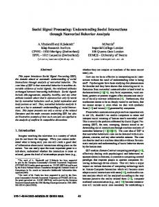
Fig. 2. Cross sectional view of a combustion chamber of an engine, where the pressure has to be measured.
1. INTRODUCTION
In this harsh environment the identification unit has to withstand temperatures up to 400°C, high temperature gradients, vibrations, and accelerations up to 2000 g. The solution has to be compatible with existing systems, i.e. no extra lines and extremely high isolation to existing lines, which are connected to a sensitive charge amplifier. A further requirement is the mechanical compatibility with existing sensors, i.e. the ID-tag has to be small enough to fit into the whole AVL sensor series, and must not add substantial costs. A high-temperature stable SAW identification tag with an interrogation unit operating in the microwave range turned out as the solution of choice, which fulfils all the criteria mentioned above.
Identifying individual sensors is often desired, in particular when sensors are frequently replaced or recalibrated, as e.g. in test blocks for combustion engines. A commercially available pressure sensor from AVL, as shown in Fig. 1, which is typically mounted close to the combustion chamber of an engine as can be seen in Fig. 2, has to be identified, and therefore, was equipped with an identification (ID) tag. The aim of the identification is to automatically assign correct calibration data and to monitor hours of operation. With an ID-tag placed inside of a sensor unit instead of being attached to the end of the sensor cable, as in existing solutions, cables can be disconnected to reduce set-up time without the need of carefully reconnecting sensors to assigned connectors. This reduces set-up time as well as prevents from incorrect measurements caused by wiring errors and the use of incorrect calibration data.
2. SYSTEM CONCEPT The concept of the presented identification system and the integration in existing sensor systems is sketched in Fig. 3. In the given example an AVL pressure sensor operating under extreme environmental conditions is equipped with the additional identification tag. The sensor, when installed in the combustion chamber of an engine, is exposed to high pressure, temperature, vibration, and shock. Such a harsh environment excludes identification solutions based on conventional semiconductor devices. The pressure sensor employing the piezoelectric effect is connected to a sensor
19,2 mm
Fig. 1. Photograph of an AVL pressure sensor that is equipped with an identification tag.
672
Proceedings, XVII IMEKO World Congress, June 22 – 27, 2003, Dubrovnik, Croatia
TC1
Proceedings, XVII IMEKO World Congress, June 22 – 27, 2003, Dubrovnik, Croatia
evaluation unit consisting of a charge amplifier in the first stage. It is important not to reduce the extremely high isolation resistance in the signal path, essential for sensitive charge measurements. Thus, a direct coupling to the existing measurement lines is out of question. The identification system may only use the existing shielded connection without direct ohmic contact. The RF-interrogation unit is capacitively coupled to the signal line and the SAW ID-tag inside the pressure sensor is inductively coupled to preserve high resistance. The RFinterrogation unit is controlled by the sensor evaluation unit. In addition to performing measurements with the attached sensor, the evaluation unit identifies the sensor ID from the connected sensor. A database in the background, networked to all evaluation units, provides additional information like calibration data or duration of life-time of the identified sensor. With this approach, all components remain interchangeable, but calibration information is up-to-date at every evaluation unit and all measurement configurations are uniquely identifiable.
Sensor Evaluation Unit measured quantity
The identification information itself is coded on a SAW ID-tag, which is fabricated on different types of temperature stable LiNbO3 substrate. A crucial point is the high temperature durability of substrate and metallization. Functionality has been successfully proven with tags heated up to 400°C, for temperature gradients of more than 70°C along the length of the ID-tag, and accelerations up to 3500 g. For the problem on hand – encoding of a digital number – the SAW tag is considered as a one-port device with an IDT connected to an antenna and interrogated wirelessly. The tag is uniquely marked with a 5-digit number that is encoded by the position of reflectors or further IDTs, placed on the tag in a predetermined grid as sketched in Fig. 4.
Sensor cable ID-TAG
RFInterrogation Unit
Reflector
Reflector
0 1 2 3 4 5 6 7 8 9
0 1 2 3 4 5 6 7 8 9
Code digit k
Code digit k+1
SAW ID-tag
IDT
Pressure Sensor
Charge Amplifier
TC4
Antenna
Fig. 4. Principle of the coding scheme of the serial number with realized with reflectors and one IDT.
Sensor
high ϑ high dϑ/dx high p
The IDT generates an acoustic wave that propagates along the surface of the substrate. When a reflector is hit, the wave is partly reflected back to the IDT. The time of travel between transmission and reception is ideally proportional to the distance between IDT and reflector. Determining reflector locations and hence the tag ID-code are thus based on time-of-travel measurements of the acoustic wave from transmission by the active IDT to the reflectors and back. As external parameters such as temperature, mechanical stress or bending may cause a change in the delay experienced by the traveling wave, additional information hast to be coded on the SAW-device to obtain a correct framing information for decoding the data bits. The tiny SAW ID-tag is mounted inside the hermetically sealed pressure sensor. A small antenna on the substrate allows for an inductive coupling thus preserving the high isolation resistance. In Fig. 5 the arrangement of the tag inside the sensor is shown.
Sensor-id
Fig. 3. Sketch of the sensor identification system, consisting of the pressure sensor with ID-tag, the sensor cable, which is disconnectable at both sides, and the sensor evaluation unit with the additional RF-interrogation unit for the ID-tag.
3. SAW IDENTIFICATION TAG Physically based on the piezoelectric effect, a SAW device consists of periodic metallic structures (interdigital transducers (IDT), reflector and coupler gratings) deposited on the plan-polished substrate surface [1]. Due to the piezoelectric effect an electric signal at an IDT will stimulate a mechanical wave that propagates along the surface of the tag. Vice-versa, a microacoustic wave arriving at an IDT causes an electric charge distribution and hence an electric signal at the terminals of the IDT. An important feature of SAW devices is a wave propagation velocity five orders of magnitude slower than the velocity of light in vacuum, which allows the realization of delay times in the microseconds range even at small chip sizes [2]. Conventional SAW devices are employed for implementing delay lines, resonators, filters, and oscillators for television receivers, mobile communications units, and many more [3]. Furthermore, SAW devices are well suited for building low-cost sensors [4–7] for many physical and also chemical quantities, and in the application as identification tags [8]. Advantages of SAW ID-tags are their completely passive operation and the possibility to interrogate them wirelessly at short distances.
Tag holder
Sensor housing
SAW ID-Tag
Fig. 5. Schematic arrangement of the SAW ID-tag mounted inside of the sealed pressure sensor.
A great advantage of the SAW technique is the completely passive operation, which means that there is no need for an additional power supply. 673
Proceedings, XVII IMEKO World Congress, June 22 – 27, 2003, Dubrovnik, Croatia
TC1
Proceedings, XVII IMEKO World Congress, June 22 – 27, 2003, Dubrovnik, Croatia
hardware e.g. generating a frequency ramp, and performing a signal preprocessing.
4. RF INTERROGATION UNIT The interrogation unit has to generate and transmit a response signal to the ID-tag and determines the coded number by evaluating the reflected receive-signal which means the measurement of S11 of the ID-tag. The frequency of operation is not restricted to ISM-bands due to the limitation of free space propagation to regions, which are completely shielded. In general, there exist two basic principles to interrogate SAW devices, either in time-domain or in frequency-domain [9, 10]. A request in time-domain needs a pulse generator delivering short RF-bursts and a fast sampling stage. With a Dirac pulse as request signal we directly get the impulse response of the ID-tag, describing the tag’s behaviour completely. Practical realizations use bursts with RF-carriers and cover a bandwidth that is inversely proportional to the burst length. The advantage of a fast measurement has to be paid by a costly sampling stage. With frequency domain sampling on the other hand a continuous wave (CW) signal is used with a comparatively moderate sampling rate. For the – not time critical – identification of a serial number a CW principle with frequency stepping (FS) as modulation scheme is used. A block diagram of the built interrogation unit is shown in Fig. 6.
5. SIGNAL EVALUATION Final ID-tag identification is done on a personal computer (PC) on which the pressure sensor evaluation is running and that is connected to the calibration data management system. After preprocessing the measured raw data in the interrogation unit are transferred from the µC to the PC. As raw data are measured in the frequency-domain the time-domain response is calculated by an inverse fast Fourier transformation (FFT) or by frequency estimation algorithms [11]. Start-frequency, measurement bandwidth, and frequency increments are independently and adaptively chosen by the evaluation software to compensate possible deviations in the resonance frequency of individual SAW devices. In the following step peak positions of the time-domain response, caused by the reflectors or IDTs and containing the code information, are determined. The coded number is assigned by comparing the calculated peak positions to the imagined grid defined in the coding scheme. For a correct identification a peak-position accuracy of better than 10 ns is necessary. As a high resolution is also obligatory to resolve individual digits the applied window-function is a trade-off between main-lobe width and side-lobe level.
Signal generation Power amplifier
Coupling + Tag
6. MEASUREMENT RESULTS
Hybrid VCO
DUT
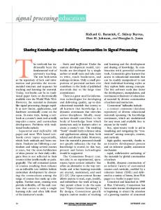
In Fig. 7 time-domain plots for different serial numbers (a) ‘080150’, (b) ‘09039’, and (c) ‘56300’ are shown. As for these measurements tags with a series of IDTs instead of reflectors were used, the interesting code block, marked by dashed lines, is preceded by large spurious responses. These signals are caused by inner reflections in between the individual digits. With a proper design the spurious signals are decayed enough in the code block section, thus a correct identification is possible. SAW ID-tags with reflectors basically exhibit lower preceding spurious signals and can be designed shorter, due to the fact that the SAW propagates the path twice. Series of tests showed the reliability under the required constraints in the considered application.
Mixer
PLL
LO
RF
IF
Converter
µC
Filter
TC4
LNA
ADC
Fig. 6. Block-diagram of the low-cost reader unit.
Signal generation is done by a phase locked loop (PLL) stabilized oscillator which is capable of delivering exact frequency points for highly linear stepped ramps. The VCO signal is amplified by a power amplifier and sent to the device under test (DUT), which represents the coupling between interrogation unit and measurement line, as well as between measurement line and SAW device, the measurement line, and finally the ID-tag itself. Transmit- and receive-signal are separated by a low-cost quadrature hybrid instead of a frequently used circulator. Additional 3 dB signal losses are acceptable with concurrent advantages in price, bandwidth and isolation of the hybrid compared to a circulator. In the applied homodyne principle the received signal is mixed with a part of the transmit signal. Next, the amplified mixer output is low-pass filtered, sampled, and digitized. A microcontroller (µC) is used for both, controlling the RF-
7. CONCLUSIONS A low-cost sensor identification technique for the application under harsh environmental conditions and compatible with existing AVL pressure sensors was introduced. Only minor modifications are necessary to upgrade existing sensors with ID-tags. Above all, the presented solution operates completely passive and does neither disturb the original sensor signal, nor exhibit direct contact to the sensor lines. Temperature resistance is guaranteed up to at least 400°C and with new materials [12], currently under investigation, possible much higher. With the current design 100.000 unique numbers can be identified. A small size, high temperature stability, and indirect coupling make this approach suitable for many identification tasks in industrial applications. 674
Proceedings, XVII IMEKO World Congress, June 22 – 27, 2003, Dubrovnik, Croatia
TC1
Proceedings, XVII IMEKO World Congress, June 22 – 27, 2003, Dubrovnik, Croatia
TC4
REFERENCES [1]
R. M. White, F. W. Voltmer, “Direct piezoelectric coupling to surface elastic waves”, Applied Physics Letters, Vol. 7, pp. 314–316, 1965. [2] D. P. Morgan, “SAW’s on lithium niobate: Properties of common orientations”, in Properties of Lithium Niobate, ser. EMIS Datareviews 5. New York: Inspec, pp. 84–93, 1989. [4] L. M. Reindl, A. Pohl, G. Scholl and R. Weigel, „SAWBased Radio Sensor Systems”, IEEE Sensors Journal, Vol. 1 pp. 69–78, 2001. [3] G. Fischerauer, “Surface Acoustic Wave Devices”, in: W. Göpel, J. Hesse, J. N. Zemel, H. Meixner, R. Jones (Eds.), Sensors. A Comprehensive Survey, Vol. 8. Weinheim: VCH, 1995. [5] L. Reindl, R. Steindl, A. Pohl, J. Hornsteiner, E. Riha, F. Seifert, “Passive Surface Acoustic Wave sensors for temperature and other measurands”, Proc. Tempmeko 1999, Netherlands, pp. 424–429. [6] J. Hornsteiner, E. Born, G. Fischerauer, E. Riha, “Surface acoustic wave sensors for high-temperature applications”, Proc. of the 1998 IEEE Freq. Contr. Symp., pp. 615–620. [7] G. Schimetta, F. Dollinger, R. Weigel, “A Wireless Pressure Measurement System Using a SAW Hybrid Sensor”, IEEE Trans. on MTT, Vol. MTT-48, No. 12, pp. 2730–2735, 2000. [8] F. Schmidt, G. Scholl, “Wireless SAW Identification and Sensor Systems”, in: C. Ruppel, T. Fjeldly (ed.), Advances in Surface Acoustic Wave Technology, Systems and Applications, Bd. 2, London, River Edge: World Scientific Publ., pp. 277–325, 2001. [9] M. I. Skolnik, Introduction to Radar Systems. New York etc.: McGraw Hill, 1979. [10] A. Pohl, “A Review of wireless SAW Sensors”, IEEE Trans. on UFFC, Vol. 47, No. 2, March. 2000, pp. 317–332. [11] A. Stelzer, M. Pichler, S. Schuster, S. Scheiblhofer, R. Hauser, “High Resolution Evaluation Algorithms for SAWIdentification Tags“, Modeling, Signal Processing, and Control Conf. at SPIE’s 10th Smart Structures and Materials Symp., 2003, San Diego, California, USA, 2003. [12] P. Krempel, G. Schleinzer, W. Wallnöfer, Gallium phosphate, GaPO4: “A New Piezoelectric Crystal Material for High-temperature Sensorics”, Sensors and Actuators A 61, pp. 361–363, 1997.
(a)
(b)
Authors: Dr. Andreas Stelzer, Institute for Communications and Information Engineering, Johannes Kepler University Linz, Altenberger Str. 69, A-4040 Linz, Austria, phone: +43 (0)70 2468-1858, fax: +43 (0)70 2468-9712, email:
[email protected]
(c)
Dr. Robert Hauser, Carinthian Tech Research (CTR), Europastrasse 4/1, A-9524 Villach, Austria, phone: +43 (0)4242 56300209, fax: +43 (0)4242 56300-400, email:
[email protected]
Fig. 7. Time-domain signals for SAW ID-tags with different codes of (a) ‘018150’, (b) ‘09039’, and (c) ‘56300’. The interesting section is located between 0.92 and 1.6 µs and marked by dashed-lines. The peaks before the marked block are due to inner reflections between code digits.
Prof. Dr. Leonhard Reindl, Institute of Electrical Information Technology, Technical University of Clausthal, Leibnizstr. 28, D-38678 Clausthal-Zellerfeld, Germany, phone: +49 (0)5323 722582, fax: +49 (0)5323 72-3197, email:
[email protected]
ACKNOWLEDGEMENTS The authors would like to acknowledge the work of colleagues and students involved in this joint project, especially Dipl.-Ing. Stefan Scheiblhofer and Dipl.-Ing. Stefan Schuster.
Dr. Rüdiger Teichmann, AVL List GmbH, Hans-List-Platz 1, A-8020 Graz, Austria, phone: +43 (0)316 787-1837, fax: +43 (0)316 787-1796, email:
[email protected]
675