In particular in [3] and [1] some of the ceiling characteriz- ing elements are ... way of the faculty and using ceiling lamps as reference land- marks. The robot was able to ..... bile robot super M.A.R.I.O. [12], a Creative webcam II and a Notebook ...
1
A low cost vision based localization system for mobile robots S. Panzieri, F. Pascucci, R. Setola, G.Ulivi Abstract| Arti¯cial vision is one of the most versatile sensory systems. It can be used in many environments such as indoor, outdoor, space, and even in underwater contexts. Most of times, vision based localization requires complex algorithms and hardware resources when related to general environment features. However, using simple landmarks can reduce dramatically the cost and the complexity of the recognition system. In typical indoor environments, in particular in o±ces, ceiling lamps are all of the same type and are placed in a quite regular way. Moreover, they can be easily seen, as generally no obstacles can exist between them and the robot vision system. These peculiarities motivated a study on the possibility of implementing a very low cost localization procedure using a standard onboard webcam. Inexpensive hardware implies several problems: among the others, the need for a procedure that compensate for optical distortions, the poor quality of image, and the slow transfer rate. The paper describes the results of this study, with an emphasis on the implementation issues. Keywords| Localization, Vision, Mobile Robots.
I
N the last years there has been an increasing interest around localization systems for autonomous mobile robots. More and more often vision is added to the localization system of mobile robots in order to reduce the odometric errors due to the incremental nature of those sensors. Indeed, the use of natural or arti¯cial landmarks allows both simple resetting of odometric errors, so that sensors can restart each time with the correct absolute position information [1], and more complex sensor fusion algorithms that integrates all available information in a single estimation process [2]. Among the others, natural landmarks have the interesting features that avoid any change in the work environment. In indoor environments one can ¯nd many di®erent reference points and marks that can be interpreted as natural landmarks, e.g. doors, corners, geometry of the °oor. In particular in [3] and [1] some of the ceiling characterizing elements are suggested as natural landmarks in order to avoid any occlusion problems. Unfortunately, visual based control schema requires, generally, very complex algorithm and dedicated hardware [4]. In this paper we have explored the possibility to realize a localization system for a mobile robot using very low cost standard hardware, i.e. a PC with a 40$ webcam. To this end we have mounted the webcam on the mobile robot focused to the ceiling and used the lamps as reference points. Moreover, we have used a suitable topological representation of the environments, i.e., we represent the environment by means of a graph where each node is a location of interest and the arcs capture the connectivity of the space. So the localization system uses the information about the position of each lamp to localize the robot on the graph
and then inside the environment. Nevertheless, given the repetitive nature of the lamps, the system needs to label and track each lamp in the image sequence in order to avoid any wrong interpretation of the environment. This imposes an upper limit on the robot speed in order to guarantee that each lamp met by the robot on its path appears at least in one webcam image. Further, the presence of low cost hardware generates some drawbacks. The ¯rst of all is due to the limited transfer rate that, in addition to the time consumed by the feature extraction algorithm, generates a considerable time delay in the loop. Also the poor quality of the image generated by the camera and the optical distortion introduced by its lens system should be taken into account especially when vision is used for precise positioning tasks. The presence of these limits have suggested the use of a two stage localization scheme: ² While the robot is moving toward the target location, the algorithm uses a lower resolution set-up for the camera to maximize the frame rate throughput and relax the constraint on robot speed. ² In the neighborhood of the target location, the system sets the resolution at the maximum one and uses also a procedure to compensate the optical distortion to guarantee a ¯ne and accurate positioning of the robot. The proposed localization system has been experimentally tested on a mobile robot going through the passageway of the faculty and using ceiling lamps as reference landmarks. The robot was able to position itself in the front of a speci¯ed door and go inside, adjusting on the °y its motion path. The paper is organized as follows: in Section I we de¯ne the topological map used to describe the faculty environment. In Section II we detail the vision system and, in Section III, the camera calibration and lamps recognition problems are illustrated. In Section IV the planning and navigation system is introduced while Section V is devoted to the experimental set-up and results, including a characterization of the obtained accuracy. Finally, Section VI presents some conclusive remarks and the planned future work, such as an extension of the idea to other, more demanding, situations. I. An Augmented Topological Map Approach It is well known that an e®ective environment representation for a mobile robot must describe all the essential features necessary for self-localization, motion planning and navigation. Moreover, the robot should be able to extract the features directly from sensory data.
2
end
Endcorridor
1
corridor doors
(go out)
Start
Lamp 1 Y=0m
2
Corridor (follow)
3
Lamp 2 Y=3m
Lamps corridors 4
target
Lamp 6
Corridor (stop)
Lamp 7
Y=15m
5
corner
Goal 8
Corner (turn right)
7
6
Y=6m
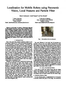
Fig. 1. Topological map
The mapping approaches, i.e., the way the world is represented, that have been proposed in literature can be grouped in two main classes [6]: metric maps and topological maps. In the metric maps the environment is represented in terms of geometric relations between the objects and a ¯xed reference frame. On the other hand, in a topological map, only adjacency relations between objects are represented [7], avoiding metric information as far as possible. Metric maps and topological maps are two di®erent representations of the same environment: as a consequence, they exhibit complementary rather than opposite properties. Metric maps are adequate to represent sensor delivered metric information and are necessary in the implementation of metric algorithms like shortest path. Unfortunately, this kind of representation is space consuming, often unsuitable for global planning and sensitive to odometric errors [10]. On the other side topological maps produce more abstract representations than a metric one. The environment can be synthetically described by a graph where nodes represent basic features (topological nodes) and arcs gives information on connections between them. Topological maps can be e®ectively used for symbolic planning in particular when considering long displacements, but they are unusable in the presence of tasks which call for accurate robot positioning. To exploit the best of both approaches the authors in [11] have suggested to put additional metric information in nodes as tags of particular interest related to the natural landmarks included in the node itself. In particular, this approach has been successfully applied for the representation of o±ce-like environments: this kind of indoor environment is usually structured with standard elements like corridors, T-junctions, corners, and endcorridor, and very often a navigation task can be expressed
as a sequence of places de¯ning a path inside the environment such as \follow the corridor and turn right at the ¯rst corner". So one has a graph representation as highlevel view of the environment (useful for the integration of the system in an arti¯cial intelligence framework), and, at the same time, metric information about length of the corridor, number of left and right doors, number of lamps in the ceiling and possibly their relative distance. Unfortunately, the extraction of some of the features mentioned before from a webcam image may be a very time-consuming task. For example the process of recognizing the shape of a corner or a T-junction using an image can be extremely hard and, perhaps, more simple sensors, like sonar or laser ones, can give better and faster results. The computational burden can be dramatically reduced if the extraction procedure is focused on particular landmarks as the lamps in the ceiling which can be easily extracted ([3], [1]). Indeed, they are well visible, easy to identify inside the image, generally all of the same type and placed in a quite regular pattern. Limiting vision system to identify only the lamps in the ceiling imposes to the graph the inclusion in the topological nodes of a labeled sequence of landmark tags associated to the lamps. Nodes are used to decide the correct navigational behavior (follow corridor, turn right at corner) and eventually to perform an approximate localization; tags are employed to re¯ne the localization process. An example of the adopted representation is shown in Fig. 1 where the planned path from Start to Goal assumes that the robot goes out of the end-corridor, follows a corridor, turns right at the corner and ¯nd the Goal in the next corridor. Once ¯nished this high-level motion, the target location (a door) can be reached with a ¯ne motion. On the way, the robot can always re¯ne its localization using landmarks (lamps) that are associated to each topological node but only a low precision is required. Note that its odometry should be able to correctly label each lamp and to handle abnormal situation (e.g., when a lamp is out of order). Near the target the estimated position must be re¯ned to correctly approach the target. The adopted representation of the environments suggests the following strategy: 1. The localization system identi¯es the position of the robot in the environment (i.e., on the graph). 2. The navigation system identi¯es on the graph the shortest path to reach the Goal location and devises the correct navigational behaviors for each node. 3. Each time a lamp appears in the webcam image, the navigation system updates the robot position and adjusts its trajectory. 4. The robot follows the path to reach the Goal where performs a ¯ne and slower motion to exactly match the target. It is important to stress that during the motion, the localization system use odometric information for a rough prediction of the landmark positions.
3
∆1 ∆1
,v
∆2
,u
d
1 d
d
1 ,u
2
2 ,u
1 ,v
,u
d
2 ,v
d
3 ,v
∆2
,v
∆3
,v
P Fig. 2. Vision system v
Y 0
V
1 7
Y
1 1 5
U
2 2 3
d 2 3 1
Fig. 3. Two pixel YUV code
u
3 ,u
3 ∆3
,u
Fig. 4. Correction of a point inside the grid: dashed line are the webcam image, while continuous represent the distortion free grid
II. Vision system The vision system used in this work has a camera-onboard con¯guration (see the Fig. 2). The low cost webcam mounted on the mobile robot is based on the VLSI vision chipset (\CPiA"), and it is connected to a notebook running Linux through the parallel port. The frame format used by the webcam consists of three parts, the Frame Header, the Video Lines and the End Of Frame code: Frame Header : each frame of video is preceded by a 64 bytes header, which contains information about the image format and compression of the video data together with status information about the camera. This allows the host to monitor the health and the performance of the camera without having to continuously poll it; Video Lines: contain video lines data: each line start with 2 bytes containing the number of bytes on the line; this number is the data bytes length plus the EOL (End Of Line) code. Between the start bytes and the EOL there is the actual video data samples. The number and format of data vary with the video mode and the compression options selected. Our driver works only in YUV 4:2:2 video mode (see below), without compression: we always obtain the entire picture from the webcam ; End Of Frame Code: is a particular bytes sequence, that codes the EOF (End Of Frame). As said before, the used Linux webcam driver (CPiALinux-driver1.5) gets only YUV 4:2:2 image without time compression. The YUV are luminance (Y) and chroma (UV) parameter used to describe a picture [8]. The luminance is coded in the Y component, using gray scale. The U and V components give chroma information. Two pixels are packed into a 32 bit word, each pixel is composed of a luminance component (Y) and a chroma component (U or V, alternatively, as in Fig. 3). So for each pixel we have complete information about the luminance, while colour information of two pixel are mixed together. The driver output is a vector containing video lines data: each vector component containing the luminance and chroma information of a pixel and its coordinates in the image plane (Y; C; u; v). One can also set through the software some camera parameters as colours gains, brightness, contrast, saturation, exposure, and resolution. In this work
352x288 Fig. 5. A negative image of a lamp on the ceiling
we ignore the colours gains and the saturation, because we use only gray scale image. The contrast is set to its maximum value, while the brigthness is ¯xed to its least one: in this way the lamps re°ections are reduced. The algorithm dynamically computes the background brightness and then set the webcam exposure and obtain more sharp images. It is possible to set two di®erent values (low and high) for the webcam resolution. Using the high resolution (352 £ 288) the framerate is about 3 fps, while using the low resolution (176 £ 144) it increases up to 6 fps. III. Localization Algorithm A. Camera calibration Accurate calibration of cameras is a crucial step for applications that involve quantitative measurements, such as the geometrical and the dimensional ones [5]. Webcam lens aberrations must be evaluated and corrected. Using a low cost, wide angle camera this procedure become even more important. In this work we only consider camera distortion, which is related to the position of image points in the image plane, but not directly to the image quality, because we only use geometrical information in our localization system (see below). Moreover, we consider as accurately known the position of the camera in the robot
4
Major Axis Area=6483
Lamp 1 Lamp 1
Area 2=4117 Minor Axis
Area 1=4048 Lamp 2
352x288
352x288
Fig. 6. Major and minor axes, center of mass and labeling Fig. 7. Labeling of two lamps
frame. Let us de¯ne, in the image plane, the image coordinate system (−; u; v), where − represents the intersection of the image plane with the camera optical axis, while the u and v axis are respectively parallel to rows and columns of the physical pixel matrix. Due to radial and tangential distortions the image plane coordinate of a point P is given by (1) u=u ^ + ±u (u; v) v = v^ + ±v (u; v)
352x288 Area=4025
New Axes
(2)
where u ^ and v^ are the distortion-free image coordinates, and u and v are the corresponding coordinates with distortion. In order to minimize the camera distortion, the calibration procedure estimates the positional errors (±^u (u; v) and ±^v (u; v)) of each point of the image. To ¯nd these errors, a calibration grid of 8 £ 12 lines is used. During the calibration procedure the grid image from the webcam is compared with the ideal image and the positional errors (¢i;j ) of grid nodes are calculated. For the points inside the squares we consider the three nearest nodes. The distortion-free coordinates of these points is estimated as (d2;u d3;u )¢1;u + (d1;u d3;u )¢2;u + (d1;u d2;u )¢3;u ±^u (u; v) = d2;u d3;u + d1;u d2;u + d1;u d3;u (3) (d2;v d3;v )¢1;v + (d1;v d3;v )¢2;v + (d1;v d2;v )¢3;v ^ ±v (u; v) = d2;v d3;v + d1;v d2;v + d1;v d3;v (4) where ¢i;j ; i 2 f1; ::; 3g; j 2 fu; vg is the positional error of the i¡th node and di;j ; i 2 f1; ::; 3g; j 2 fu; vg is the distance between the pixel and the i¡th node. At the end of the calibration procedure the image positional error matrix E is obtained. This matrix allows to compute a distortion-free image using the equations (1) and (2). For example, in Fig. 5 it is shown the negative image of a lamp after removing the distortion. Note that, even if brightness and contrast are selected to have a minimum halo, an additional distortion that cannot be corrected is still presents. The background pattern is due to the structure of the ceiling.
inside
outside Fig. 8. Completing partial view
B. Lamps recognition After the calibration step the algorithm proceeds analyzing the image. Remember that typical image processing algorithms use complex strategies to reduce the computational burden and good public domain implementation are quite common on the world-wide web. First, a three search of all connected components is performed comparing, for each pixel, the luminance information Y with a threshold: if the pixel luminance exceeds the threshold then is considered, otherwise is neglected. Two pixels are connected if they satisfy the following proximity condition: (P1 ; P2 ) , (ju1 ¡ u2 j · 1 ^ jv1 ¡ v2 j · 1)
(5)
where Pi is the i¡th pixel, (ui ; vi ) its coordinates. This connection is also called 8-adjacence. After this scanning, more than one connected component are usually retrieved. Sometimes re°ections can produce small connected components that can be discriminated evaluating their area. Our lamps produce an image that is around 6300 pixels; we suppose to have lamps only if the area is greater then 3500 pixels. From the area we also know how much of the lamp is in the viewing window and how much is left out. After that, to better the quality of
5
the image the morphological operators of erosion and dilation are applied to reduce fringes caused by small re°ection along borders of the lamp. This e®ect is more evident when lamps are far from the center of the image and the light reaches the camera after re°ecting on the common metallic grids that are always set over the luminescent elements. At this point we deduce the robot position and orientation using the lamps con¯guration in the image plane. To do this we compute the center of gravity (CoG) and the orientation of each lamp with the well known formulas ³ PN Y (u ¡ 0:5) PN Y (v ¡ 0:5) ´ i i i=0 i i (6) ; i=0PN (uc ; vc ) = PN i=0 Yi i=0 Yi µ=
³ 2¹1;1 ´ 1 u;v tan¡1 0;2 2 ¹2;0 u;v ¡ ¹u;v
(7)
where (uc ; vc ) are the center of gravity coordinates, N the pixels number of the lamps, while ¹k;h u;v is the (k; h) order central moment with respect to (u; v) (see Fig. 6 obtained from the analysis of Fig. 5). With this procedure, the system is able to recognize when a new lamp appears in the image and when the lamp disappear from it. Using the odometry (on a short range) a new incoming lamp is labeled and its CoG and orientation is calculated. To correctly use these measures the system needs a good estimate of those quantities and this is not possible when only a partial view is available. In Fig. 7 two lamps are recognized and correctly labeled but their visible area (approximately 4000) is not the full one: as a result axes are not correctly estimated and cannot be considered for odometry correction. Due to the limited view of the camera these problems may occur very often and force us to develop a recovery algorithm able to complete the missing area and correctly estimate CoG and orientation. In Fig. 8 the result of this procedure, based on the knowledge of the reconstructing shape, is shown. The procedure is performed only when the visible area is greater then 4000 pixels. The algorithm uses edges found in the area and tries to interpolate them with a least square method. The reliability of such process is not extremely high but the information retrieved is a valued one in any case. IV. Navigation Task As mentioned before, we have used the vision system to guide an autonomous mobile robot inside the passageway of our faculty. This task is logically divided into three di®erent stages: ² Path identi¯cation ² Trajectory following to the Goal ² Approaching the exact target position In the ¯rst stage, the system identi¯es on the topological map the best path to reach the speci¯ed Goal location. Suppose that the system exactly knows the robot initial position (home). The result of this plan is a sequence of ceiling lamps (i.e., landmark tags in the graph) that will be met by the robot on its way. In the second stage, a global trajectory is planned hopby-hop generating each time the commands needed at the
low level robot controller (i.e., the desired linear and angular velocity) to reach the next landmark tag. In particular, the direction of the motion is chosen in order to reach the next lamp with the shortest path, avoiding any known obstacle and trying to pass at a given distance from the center of gravity of the lamp. When a new lamp appears in the camera vision the system tries to identify it using an odometric preview and, after having labeled the lamp and calculated the geometric properties as seen in the previous subsection, uses tag values in the graph to reset all the odometric sensors. At this preliminary stage this correction is done only considering a threshold for the reliability of the measure. Note that odometric information are also used to estimate the position of the lamp in the camera image in order to correctly handle abnormal situation, i.e., a lamp out of order. After this correction, that can be performed several times with the same lamp, the piece of trajectory to the next lamp is recalculated. A separate discussion has to be made for the module of the imposed velocity that must guarantee that any lamp can be seen by the robot. Indeed, due to the time consumed by the image grabbing and processing, such speed cannot exceed a limit that depends also on the distance of the next lamp and the dimension of the image itself. This limit can be calculated step by step and tuned for the positioning accuracy required for the particular navigational behavior. For example, if the robot is following a corridor this can be done even if only one or two images are taken of a particular lamp. The last stage of the navigation task, begins when the robot is at the Goal, i.e., in the proximity of the target. The system switch to the high resolution vision scheme to guarantee an accurate positioning and plan a very ¯ne motion using both vision and odometric information. Obviously if the target position is so far from the landmarks that the lamp is out of the camera image, the robot uses only odometric information. V. Experimental results The proposed algorithm has been tested using the mobile robot super M.A.R.I.O. [12], a Creative webcam II and a Notebook (Pentium II 366MHz). The mobile platform is a unicycle robot built in our Department having a front castor and two ¯xed wheels on the same axle actuated by two independent motors. The robot sensory system is composed by two incremental encoders mounted on the two motors and connected to the on board robot minicomputer where runs the low-level control algorithm. The high-level control algorithm runs on the Notebook, connected to the on-board PC through the serial port. The webcam is mounted on the robot focused to the ceiling (see Fig. 2). The distance between the vision system and the landmarks (rectangular lamps) is about 2.50m, so each pixel is about 8mm at the 356 £ 288 resolution and about 16mm at the 176 £ 144 resolution. To understand the precision of the webcam some experiments have been conducted in the Department passageway;
6
the resulting errors are collected in the next tables. In the ¯rst experiment the robot moves in the y¡direction of the world framework, with the rectangular lamps oriented in the x¡direction, while in the second the robot turns around the camera optical axis. In both cases webcam resolution is high.
8
6 TABLE I Position error (in mm)
4
x y
Minimal error 1.6 3.2
Maximal error 15.2 32.3
Mean error 2.4 -3.2
Standard deviation 8.8 32
Note that the maximum robot position error is obtained when the lamp is at the image border, because there the distortion is greater.
2
0
− 2 TABLE II Orientation error (in deg)
'
Minimal error 0.5
Maximal error 4.5
Mean error 0.04
− 2
Standard deviation 0.5
A navigation in the department corridor is shown in Fig. 9. During this experiment the robot moves at the average speed of 4m/s along the corridor, counting the lamps: after the 5th the lamp, it turns right and enters in the robotics laboratory. VI. Conclusions In this paper we have presented a preliminary work on the use of arti¯cial vision in a low-cost localization schema for a mobile robot. The proposed approach, well suited for o±ce-like environments, uses an inexpensive webcam with standard hardware. This imposes that the features extraction algorithm must be very light. To this end we focused the vision system to identify only the lamps in the ceiling used as natural landmarks. Due to the constrains imposed by hardware devices, which limits the frame-rate of the camera, a dual resolution schema has been used. Extensive experimental tests have shown the e®ectiveness of the proposed approach, and future work will be devoted to better integrate the vision subsystem with the navigation one. More complex sensor fusion can be done merging odometric information with lamp positions, taking into account the reliability of such data and avoiding the simple reset procedure that has been implemented since now. Finally, the motion control has to be improved, i.e., the choice of the best trajectory to follow along the path to guarantee an optimal vision of all the lamps.
0
2
4
Fig. 9. Experimental navigation
Acknowledgments This work, as a part of the VERAS project, has been partially supported by italian MURST. References [1] A. Adam, E. Rivilin, and H. Rotstein, \Fusion of ¯xation and odometry for vehicle navigation," IEEE International Conference on Robotic and Automation, Los Alamitos, USA, 1999, pp. 16381643. [2] S. Panzieri , S. Renzi, G. Ulivi, \A stereo vision based docking procedure for a mobile robot," in Proc. 6th Int. IFAC Symp. On Robot Control SYROCO 2000, Vienna, Austria, 2000, pp. 403408. [3] A.B. Martinez, J. Climent, J.M. Asensio, and J. Batle, \Absolute positioning for indoor mobile robots guidance," International Symposium on Industrial Robots, Barcellona, 1992, pp. 529-532. [4] J. Amat, J. Fernandez, A. Casals, \Vision Based Navigation System for Autonomos Vehicles," Intelligent Automation Systems, ISO Press, 2000. [5] J. Weng, P. Cohen, M. Herniou, \Camera Calibration with Distorsion Models and Accuracy Evaluation", IEEE Transaction on Pattern Analysis and Machine Intelligence, vol.14, n.10, 1992. [6] J. Borenstein, H.R. Everett, and L. Feng Navigating mobile robot: sensors and techniques, Peters A K, Ltd., Wellesley, MA,1996. [7] G. Dudeck, M. Jenkin, E. Milios, and D. Wilkes, \Robotic exploration as graph construction," IEEE Trans. on Robotics and Automation, vol.7, n.6, 1991, pp. 859{865. [8] R. Schaphorst, VideoConferencing and Videotelephony: Technology and Standards, Artech House, 1999 [9] B. Kuipers, Y.T. Byun, \A robot exploration and mapping strategy based on semantic hierarcchy of spatial representation," Journal of robotics and autonomous sistems, vol. 8, 1991, pp. 47{63. [10] S. Thrun, \Learning Metric-Topological Maps for Indoor Mobile Robotn Navigation" Arti¯cial Intelligence vol. 1, 1999, pp. 21{71. [11] E. Fabrizi, S. Panzieri, and G. Ulivi, \Extracting topological features of indoor environment from sonar-based fuzzy maps," Intelligent Autonomous Systems 6, E. Pagello, F. Groen, T. Arai, R. Dillmann, A. Stentz (eds), IOS Press, Amsterdam, 2000, pp. 596{ 603. [12] Description available at http://www.dia.uniroma3.it/autom /LabRob/supermario.html