A. Al i dr.
Serijski izlazni impulsni ADC male snage u 0,18 µm CMOS postupku ISSN 1330-3651(Print), ISSN 1848-6339 (Online) DOI: 10.17559/TV-20130914070012
A LOW POWER SERIAL OUTPUT FLASH ADC IN 0,18 µm CMOS PROCESS Al Al, Mamun Bin Ibne Reaz, Md. Syedul Amin, Mohd. Alauddin Mohd. Ali, Jae Sung Yu, Tae Gyu Chang Original scientific paper This paper proposes a simple design of a flash analog-to-digital converter (ADC) in 0,18 μm CMOS technology. This ADC is expected to be used within a temperature sensor, which provides analog data output having a range of 360 mV to 560 mV. This system consists of three main blocks: the threshold inverter quantization (TIQ)-comparator, encoder and parallel input serial output (PISO) register. The design goal is to get a flash ADC with low power dissipation, small size and compatible with the temperature sensors. The method is proposed to set each of the transistor channel length, for finding out the threshold voltage difference of the inverter each on the TIQ comparator. The design has an input range of 285 to 600 mV and 6-bit resolution output. The chip area of the designed ADC is 844,48 × 764,77 µm2 and the power dissipation is 0,162 µW with 1,6 V supply voltage. Keywords: CMOS, Comparator, Flash ADC, Temperature Sensor
Serijski izlazni impulsni ADC male snage u 0,18 µm CMOS postupku Izvorni znanstveni članak U radu se predlaže jednostavan projekt impulsno analogno-digitalnog pretvarača (ADC) u 0,18 μm CMOS tehnologiji. Taj bi se pretvarač trebao koristiti u senzoru temperature, koji daje izlaz analognih podataka u rasponu od 360 mV do 560 mV. Sustav se sastoji od tri glavna bloka: threshold inverter quantization (TIQ) - komparatora, kodnog uređaja (kodera) i parallel input serial output (PISO) registra. Svrha je projekta dobiti impulsni ADC s malim gubitkom energije, malih dimenzija i kompatibilnim sa senzorima temperature. Ovom bi se metodom trebala podesiti dužina svakog kanala tranzistora u svrhu pronalaženja razlike u ulaznom naponu pretvarača na TIQ komparatoru. Projektom se predviđa ulazni raspon od 285 do 600 mV i izlaz rezolucije 6bita. Površina čipa projektiranog ADC je 844,48 × 764,77 µm2 a gubitak energije iznosi 0,162 µW uz napajanje od 1,6 V. Ključne riječi: CMOS, komparator, impulsni ADC, senzor temperature
1
Introduction
Technological developments and use of wirelesssystem applications with low power consumption have become one of the main attractions in the circuit design [1, 2]. Explosive growth of embedded sensors into radio frequency identification (RFID) tags are extensively used nowadays. In an RFID system, to read the data from sensors, a fully integrated and high performance ADC circuit is essential. This ADC is used to convert analog data into digital data format to facilitate the processing and transfer of data to the sensor implanted on RFID-Tag chip, which is integrated into the RFID system or wireless system. The design is expected to have the lower power dissipation and operating voltage, small area size subsequent circuit. The ADC design presented in this paper is a converter suitable for a temperature sensor and easy to integrate with the other circuits. The ADC is proposed for the intention, it is Flash-ADC with TIQcomparator applies, due the Flash-ADC has many advantages are high speed, high linearity, low voltage and reduce power dissipation [3, 4]. The previous researches have done a variety of methods to get the best performance of ADC. There are several flash ADC designs proposed by different researchers with very low power dissipation. An inverter based design of ADC proposed by [5], shows the lowest power dissipation of only 1,66 μW. Besides, [6] proposed SAR ADC design method with a power dissipation of 1200 μW and [7] proposed a pipelined ADC with 348 mW power dissipation. But they did not get a lower power consumption compared to Flash ADC. This paper proposes a flash ADC designed with TIQcomparator, encoder and PISO register, to obtain the best performance suitable for use in the wireless temperature Tehnički vjesnik 22, 6(2015), 1425-1431
sensor system. The aim of research is how to design a low power Flash ADC compatible with this system. 2
Material and methods
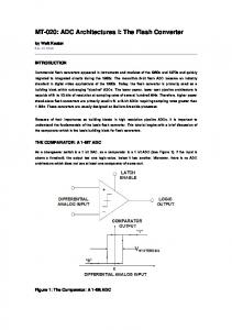
The complete system of flash ADC consists of three main blocks: TIQ comparator, encoder and PISO registers, as shown in Fig. 1.
Figure 1 Block diagram of the flash ADC
The TIQ-Comparator is functioning as data quantization of the analog data to thermometer code (TC). This part is very important for ensuring linearity and the accuracy of the data transfer. The encoder makes sharper thresholding of comparator output and provides full digital output voltage swing converting to 6-bit binary code. So, if the comparator is less efficient the output data will be less accurate. The PISO register works to process 6-bit of parallel to serial data. The temperature sensor will use this design in the range between −100° C to 200° C because the sensor shows excellent linear response in this temperature range. The sensor has a range analog output from 285 to 560 mV with the supply voltage 1,6 V and 31,14 µW power consumption. This sensor was founded on our previous research [8] and match to input of Flash ADC proposed.
1425
A low power serial output flash ADC in 0,18 µm CMOS process
A. Al et al.
2.1 TIQ comparator
The main design of TIQ comparator is converting analog data to 64-level thermometer data code as a block diagram in Fig. 3. This design is referred to that to obtain n-bit flash ADC is (2n – 1) comparator [12]. Therefore it is necessary to design a 6-bit Flash ADC is needed as much as 26 − 1 = 63 TIQ comparators. Meanwhile, to get the CMOS transistor channel L of each first inverter refers to the mathematical expression of the threshold voltage (Vth) of any quantized sub-unit can be derived approximately as Eq. (2) [13, 14].
A TIQ Comparator basic circuit consists of two cascaded CMOS inverters as shown in Fig. 2 [3]. The first inverter functions as voltage reference to the ADC system. The second inverter serves as the gain booster to keep the linearity in balance from the voltage rising and falling intervals.
VDD − Vtp + Vtn Vth =
In the previous researches there are many methods for design of TIQ-comparator, such as: the analog input signal quantization level is set in the first stage by changing the voltage transfer curve (VTC) by means of transistor sizing [9, 10], the size of both transistor channel. This research applies another method, by adjusting L and keeping W fixed. The advantages are reduced power consumption and area of the layout. Increasing L reduces the transistor drain current, ID according to [11], for a transistor in saturated condition as Eq. (1).
W 1 µ ε 2 = n ox ⋅ ⋅ 2(VGS − Vtn )VDS − VDS , L 1 t ox
(1)
(2)
Development of the comparator was based on the basic circuit given in Fig. 2 and Eq. (2). The Eq. (2) was used to calculate the PMOS transistor channel L of the first inverter, according to the desired value of threshold voltage and this result is shown in Tab. 1. The range of the threshold voltage this calculation is match necessary to the output voltage of the sensor, which is at list from 360 to 560 mV.
where ID is transistor drain current, µn is electron mobility, Ɛox is permittivity of the silicon dioxide, tox is the transistor channel width layer, W is transistor channel width, L is transistor channel length, VGS is voltage gate–source, Vtn is the voltage drain-source voltages, VDS is voltage drainsource. The first Inverter of PMOS transistor channel Channel length (µm) Channel width (µm)
.
Figure 3 Block diagram of the TIQ-Comparator
]
[
Kn 1+ Kp
Here Vtn and Vtp are the threshold voltages for NMOS and PMOS devices, respectively and Kn = (W/L)nµnCox, Kp = (W/L)pµpCox, and µn and µp are the hole and electron mobility of NMOS and PMOS respectively.
Figure 2 TIQ-comparator basic circuits
ID
Kn Kp
Table1 Calculation result of the transistor channel length and width The number of TIQ-comparator 1
2
3
4
5
6
7
8
9
10
11
12
13
14
15
16
17
18
19
20
21
0,51 0,54 0,58 0,62 0,66 0,71 0,78 0,84 0,92 1,08 1,11 1,2 1,32 1,45 1,60 1,75 1,95 2,16 2,38 2,62 2,91 1,4 1,4 1,4 1,4 1,4 1,4 1,4 1,4 1,4 1,4 1,4 1,4 1,4 1,4 1,4 1,4 1,4 1,4 1,4 1,4 1,4
Figure 4 TIQ comparator schematic with the L channel varying 1426
Technical Gazette 22, 6(2015), 1425-1431
A. Al i dr.
Serijski izlazni impulsni ADC male snage u 0,18 µm CMOS postupku
Further implementation of the design is done as follows: the design size of the L and channel W of the second inverter are fixed, according to the design standard of the 0,18 µm CMOS Technology. The standard design is 0,18 µm of L and 1,4 µm of W for PMOS and NMOS transistors respectively. Here, PMOS transistor’s W on the first inverter is made on 1.4 µm fixed, whereas the channel length is different and these techniques are followed to next inverters, according to Fig. 4. However, NMOS of all inverters remain same ratio of W and channel L. The calculation is made starting with the most
significant bit (MSB) of quantized to the least significant bit (LSB) with the value of Vth, 600 to 285 mV. In this calculation, it is obtained the size of the channel L for the comparator no. 1 to no. 21 only, with the channel L from 0,51 µm to 2,91 µm as shown in Fig. 4. For the next comparator no. 22 to no. 63 are inserted one or two PMOS transistor as compensation in diode connection, to complement the achievement of the expected voltage input range to the lower side. The compensation transistor inserted between VDD to the first inverter PMOS transistors as shown in Fig. 5.
Figure 5 TIQ Comparator with CMOS compensation
Figure 6 Grey code circuits
2.2 Grey code circuits In the previous research works, many methods have been utilized for the design of the encoder circuit. There are: Fat-tree encoder [15]; MUX-based encoder [16, 17]; bubble error correction (BEC) circuit [18]; ROM Tehnički vjesnik 22, 6(2015), 1425-1431
based encoder [19]; logic-based encoder [20]. All the methods are proposing the same advantages such as high speed, high resolution, low power etc. Logic-based encoder is the best performance [21] and match to propose design. Due in this design is two the important points are low power and simple circuit. For these 1427
A low power serial output flash ADC in 0,18 µm CMOS process
A. Al et al.
benefits of low power and simple circuit, the encoder is redesigned, implementing the circuits by using CMOS logic gates in CEDEC standard library. In this process, the encoder has two functions: to eliminate the bubbleerror and convert 64-level thermometer code to 6-bit binary. The bubble error is the result of many sources, for instance, clock jitter, device mismatch, offset voltage. The input thermometer code of a circuit is invalid code and there is no correction circuit, consequently output of the ADC in this case is incorrect [18].
Circuits of the proposed encoder consist of gray circuits and decoder circuits. The grey circuit contains NOT, AND and OR gate configuration as in Fig. 6. Output of the grey circuits follows to the decoder circuits convert to 6-bit binary code. The decoder circuits contain EXOR-gate configuration as in Fig. 7 where, T is a thermometer code with T63 is LSB and T1 is MSB. G is a grey code with G0 is LSB and G5 MSB. Follow expression, b is binary code with b0 is LSB and b5 is MSB and b5 = G5, b4 = G5 (+) G4, b3 = b4 (+) G3b2 = b3 (+) G2. Converting 64-level TC to BCs is shown in Tab. 3. The Booleans algebra can be expressed as: G5 = T32, G4 = T48.T16, G3 = T56.T40 + T24.T8 , G2 = T60.T52 + T44.T36 + T28.T20 + T12.T4 , G1 = T62.T58 + T54.T50 + T46.T42 + T38.T34 + T30.T26 + T22.T18 + T14.T10 +T6.T2 , G0 = T63.T61 + T59.T57 + T55.T53 + T51.T49 + T47.T45 + T43.T41 + T39.T37 + T35.T33 + T31.T29 + T27.T25 + T23.T21 + T19.T17 + T15.T13 + T11.T9 + T7.T5 + T3.T1 b1 = b2 (+) G1, b0 = b1 (+) G0
Figure 7 Decoder circuits
The thermometer code convert to gray code and convert to 6-bit binary are shown in the Tab. 2.
Table 2 Thermometer code to gray code and to 6-bit biner
No 0 1 2 3 4 32 61 62 63
T63 T62 T61 0 0 0 0 0 0 0 0 0 0 0 0 0 0 0 0 0 0 0 0 1 0 1 1 1 1 1
Thermometer Code - T32 T4 0 0 0 0 0 0 0 0 0 1 0 0 1 1 1 1 1 1 1 1 1 1
T3 0 0 0 1 1 1 1 1 1
T2 0 0 1 1 1 1 1 1 1
T1 0 1 1 1 1 1 1 1 1
G5 0 0 0 0 0 1 1 1 1
G4 0 0 0 0 0 0 1 1 1
Gray Code G3 G2 G1 0 0 0 0 0 0 0 0 1 0 0 1 0 1 1 0 0 0 0 0 1 0 0 0 0 0 0
G0 0 1 1 0 0 0 1 1 0
b0 0 0 0 0 0 1 1 1 1
b1 0 0 0 0 0 0 1 1 1
6-bit binary b2 b3 0 0 0 0 0 0 0 0 0 1 0 0 1 1 1 1 1 1
b4 0 0 1 1 0 0 0 1 1
b5 0 1 0 1 0 0 1 0 1
2.3 PISO register
3
Parallel input serial output (PISO) register is functioning as converting parallel 6-bit binary to serial output as in Tab. 4. The low power of shift register design was proposed by [22], using D flip-flop in weak inversion region. For the efficient design of the register was used D flip-flop by [23]. In this design, the PISO register circuit is configured of D-FF with load and clock control as in Fig. 8. Both their controls are arranging data shifting in the shift-register system. Parallel 6-bit binary data convert to serial output data are shown in Tab. 3.
The circuit design is designed and simulated by using the tools of the Mentor Graphics Design Architect (DA) CEDEC_KIT. The design and simulations are carried out to achieve a linear quantization value repeatedly. To obtain a linear quantization value in the simulation of 0.0 V to 0.61 V is given by the DC input signal as Fig. 9, while to obtain a frequency response of quantization from 1 to 10 KHz is given by the AC signal input as in Fig. 10. In Fig. 9, it is shown that the conversion of analog input to quantization output responding range from 0,285 V to 0,6 V. During the increment of 5 mV in the DC input, the quantization output increases 1 level. Fig. 10 illustrates the simulated result of the TIQ Comparator designed on 64 levels of quantization with the sinusoidal input voltage of 0 V to 0,6 V - peak at the frequency 10 kHz and half wave positive transition. This graphical response exhibits a good linearity and sensitivity with linear rise and fall of the input signal.
CLK 0 1 2 3 4 5 6
1428
Table 3 Parallel 6-bit binary to serial on 1 byte data Parallel Data Input Serial B5 B0 B4 B3 B2 B1 Output MSB LSB 1 0 1 0 1 0 X X 1 0 1 0 1 0 LSB X X 1 0 1 0 1 X X X 1 0 1 0 X X X X 1 0 1 X X X X X 1 0 X x X X X X 1 MSB
Results and discussion
Technical Gazette 22, 6(2015), 1425-1431
A. Al i dr.
Serijski izlazni impulsni ADC male snage u 0,18 µm CMOS postupku
Figure 8 6-bit PISO Register circuits
matches Tab. 3 of design principle. Fig. 12 is showing the simulation results of PISO registers with 6 bit binary parallel input and serial output. Pulse clock (V clock) function as shift control on register and pulse load (V load) for reset of the register every one byte data transfer. The final layout design of the chip is shown in Fig. 13. The chip design consists of three main blocks: TIQcomparator, encoder and PISO register. Around the circuit is added pad terminal to connect the circuits with the power supply as well as input and output pin. All of the blocks of the flash ADC integrated in this chip, with the layout size 844,48 × 764,77 µm2. Figure 9 Quantized output for the DC input voltages 0 to 0,61 V
Figure 12 The simulation results of PISO register
Figure 10 Quantized output for the sine input voltage of 0,61 V and frequency of 10 KHz
Figure 13 The Layout design
Figure 11 The encoder output graph with the signal input rising
The Encoder output graph is shown in Fig. 11. This output is the result of simulation synchrony to Fig. 8 and Tehnički vjesnik 22, 6(2015), 1425-1431
Tab. 5 shows the comparison result of the proposed ADC with other Flash ADC architectures. It can be seen that the proposed design shows the lowest power dissipation because of judicious choice of W/L of the CMOSs. The layout area of the design is shown in Fig. 13 1429
A low power serial output flash ADC in 0,18 µm CMOS process
with the pad terminal included, whereas the other designs are featured by excluding pad terminal. The total area of the circuit including pads is (844,48 × 764,77) µm2.
A. Al et al.
However this layout size of the pad depends on the library CEDEC standard design. Hence, the proposed design did not appear the smallest layout size in Tab. 4.
Table 4 The comparison of the proposed design to the other flash ADCs
References [3] [5] [19] [24] [25] [26] [27] [28] [29] [30] [31] Proposed design
4
Architecture/Method Flash/TIQ technique Flash/comparator redundancy Flash/ extend the TIQ Flash/data trees Flash/TIQ technique Flash/TIQ technique and sh circuit Flash/sh circuit Flash/reference voltage and common mode calibration Flash Flash/Sub Flash Flash/Time domain comparator Flash/TIQ Comparator
Conclusion
The flash ADC is designed and verified by using the Mentor Graphics VLSI Design Software. The final chip is designed by CEDEC industry standard I/O cell library for fabrication lab Silterra Malaysia. It consists of 63 pairs of CMOS inverters in the-TIQ comparator part, the logic based is used for the encoder part, and D FF for the PISO register development. The design has an input range of 285 to 600 mV and 6-bit resolution output. The chip area of the designed ADC including pads is 844,48 × 764,77 µm2.The power dissipation is only 0,162 µW in 1,6 V supply voltage and the sinusoidal input voltage of 0V to 0,6 V peak at the 10 kHz frequency and positive half wave transition condition. This design is suitable for use in the wireless temperature sensor system. Acknowledgments This work is supported by the research grant ETP2013-37 from Universiti Kebangsaan Malaysia, Malaysia and is also partially supported by the Chung-Ang University, Seoul, South Korea Research Scholarship Grant in 2013. 5
References
[1] Uddin, M. J.; Nordin, A. N.; Reaz, M. B. I.; Bhuiyan, M. A. S. A CMOS Power Splitter for 2, 45 GHz ISM BAND RFID Reader in 0,18 µm CMOS TECHNOLOGY. // Tehnicki Vjesnik-Technical Gazette. 20, 1(2013), pp. 125129. [2] Bhuiyan, M. A. S.; Reaz, M. B. I.; Jalil, J.; Rahman, L. F.; Chang, T. G. Design Trends in Fully Integrated 2.4 GHz CMOS SPDT Switches. // Current Nanoscience. 10, 3(2014), DOI: 10.2174/15734137113096660106 [3] Yoo, J.; Choi, K.; Lee, D. Comparator Generation and Selection far Highly Linear CMOS Flash Analog to Digital Converter. // Journal of Analog Integrated Circuits and Signal Processing. 35, 2(2003), pp. 179-187. DOI: 10.1023/A:1024134700921 [4] Iyappan, P.; Jamuna, P.; Vijayasamundiswary, S. Design of analog to digital converter using CMOS logic. // International Conference on Advances in Recent 1430
Design CMOS technology (µm) 0,25 0,18 0,18 0,35 0,18 0,35 0,18
Supply voltage (V) 2,375 to 2,65 0,2 to 0,9 1,8 5 1,8 2,5 1,8
Power dissipation (µW) 35 250 1.66 36 980 500 000 20 000 5000 5300
Layout area (µm) 228 1 960 000 8 000 000 -
0,065
1,2
4000
130 000
0.090 0,065 0,18 0,18
1,2 1,0 1,8 1,6
1919 15 000 8000 0,162
1 000 000 13 200 645 832
Technologies in Communication and Computing. / Kottayam, 2009, pp. 74-76. [5] Daly, C. D.; Chandrakasan, P. A. A 6-bit, 0.2 V to 0.9 V highly digital flash ADC with comparator redundancy. // IEEE Journal of Solid State Circuits. 44, 11(2009), pp. 3030-3038. DOI: 10.1109/JSSC.2009.2032699 [6] Wu, H.; Li, B.; Huang, C. W.; Wang, P. Y. A 1.2V 8-bit 1MS/s SAR ADC with res–cap segment DAC for temperature sensor. // LTE Analog Integr. Circ. Sig. Process. 73, 1(2012), pp. 225-232. DOI: 10.1007/s10470-0129890-z [7] Sahoo, D. B.; Razavi, B. A. 12-Bit 200-MHz CMOS ADC. // IEEE Journal of Solid State Circuits. 44, 9 (2009), pp. 2366-2380. DOI: 10.1109/JSSC.2009.2024809 [8] Al, A.; Reaz, M. B. I.; Motakabber, A. M. S.; Ali, M. A. M. A single-chip proportional to absolute temperature sensor using CMOS technology. // Waset conference / Paris, 2012, pp. 1192-1194. [9] Tangel, A.; Choy, K.The CMOS Inverter as a Comparator in ADC Designs. // Journal Analog Integrated Circuits and Signal Processing. 39, 2(2004), pp. 147-145. DOI: 10.1023/B:ALOG.0000024062.35941.23 [10] Chauhan, S. S.; Manabala, S.; Bose S. C.; Chandel, R. A. New Approach to Design Low Power CMOS Flash A/D Converter. // International Journal of VLSI design & Communication Systems (VLSICS). 2, 2(2011), pp. 100108. [11] Uyemura, P. J. Fundamentals of MOS digital integrated circuits reading, Addison-Wesley Publishing Company, Massachusetts, 1988. [12] Khot, S. S.; Wani, P. W. Design of a 45 nm TIQ Comparator for High Speed and Low Power 4 Bit Flash ADC. // Proceeding of 20th International Conference on Advances in Electrical & Electronics / Trivandrum, 2010, pp. 6-10. [13] Celebi, A.; Aytar, O.; Tangel, A. A 10-bit 500 Ms/s Twostep Flash ADC. // IEEE International Conference on Computer as a tool / Belgrade, 2005, pp. 898-901. [14] Rajashekar, G.; Bhat, M. S.Design of Resolution Adaptive TIQ Flash ADC using AMS 0.35 μm Technology. // International Journal of information and Communication Technology. 2, 1(2009), pp. 1-6. [15] Rajeswari, P.; Ramesh, R.; Ashwatha, R. A. An Approach to Design Flash Analog to Digital Converter for High Speed and Low Power Applications. // International Journal of VLSI design & Communication Systems. 3, 2(2012), pp. 125-131. DOI: 10.5121/vlsic.2012.3211 Technical Gazette 22, 6(2015), 1425-1431
A. Al i dr.
[16] Arunkumar, P. C.; Rekha, G.; Narashimaraja, P. Design of a 1.5-V, 4-bit Flash ADC Using 90 nm technology. // International Journal of Engineering and Advanced Technology. 2, 2(2012), pp. 274-276. [17] Sandner, C.; Martin, C. M.; Santner, A.; Hartig, T.; Kuttner, F. A 6-bit 1.2-GS/s Low-power Flash-ADC in 0.13 μm digital CMOS. // IEEE Journal of Solid State Circuits. 40, 7(2005), pp 1499-1505. DOI: 10.1109/JSSC.2005.847215 [18] Hieu, V. B.; Beak, S.; Choi, S.; Seon, J.; Jeong, T. T. A New Approach to Thermometer-to-binary Encoder of Flash ADCs-bubble Error Detection Communications and Electronics. // 3rd International Conference on IEEE Conference Publications / Seoul, 2011, pp. 1-4. [19] Kulkarni, M.; Sridhar, V.; Kulkarni, G. H. The Quantized Differential Comparator in Flash Analog to Digital Converter Design. // International Journal of Computer Networks & Communications. 2, 4(2010), pp. 37-45. DOI: 10.5121/ijcnc.2010.2404 [20] Kumar, P.; Kolhe; A. Design & Implementation of Low Power 3-bit Flash ADC in 0.18 µm CMOS. // International Journal of Soft Computing and Engineering. 1, 5(2011), pp. 71-74. [21] Madhumati, M. G. L.; Rao, K. R.; Madhavilatha, M. Comparison of 5-bit Thermometer-to-binary Decoders in 1.8 V, 0.18 μm CMOS Technology for Flash ADCs. // IEEE International Conference on Signal Processing Systems / Singapore, 2009, pp. 516-520. [22] Andrawes, S.; Koushaeian, L.; Veljanovski, R. Mulithreshold Low Power Shift Register. // International Journal of Circuits Systems and Signal Processing. 3, 1(2009), pp. 1487-1495. [23] Nayeem, N. M.; Hossain, A. M.; Jama,l L.; Hafiz, M.; Babu, H. Efficient Design of Shift Registers Using Reversible Logic. // IEEE International Conference on Signal Processing Systems / Singapore, 2009, pp. 474-478. [24] Shahramian, S.; Voinigescu, S. P.; Carusone, A. C. A35GS/s, 4-Bit Flash ADC with Active Data and Clock Distribution Trees. // IEEE Journal of Solid State Circuits. 44, 6(2009), pp. 1709-1720. DOI: 10.1109/JSSC.2009.2020657 [25] Agrawal, N.; Paily, R. A Threshold Inverter Quantization Based Folding and Interpolation ADC in 0.18 μm CMOS. // Journal Analog Integrated Circuits and Signal Processing. 63, 2(2010), pp. 273-281. DOI: 10.1007/s10470-009-9388-5 [26] Rajput, A.; Kanathe, S. Implementation of Flash ADC with TIQ Comparator. // International Journal of Engineering & Science Research. 2, 10(2012), pp. 1462-1466. [27] Senthil, S. M.; Banupriya, M. High Speed Low Power Flash ADC Design for Ultra-Wide Band Applications. // International Journal of Scientific & Engineering Research. 3, 5(2012), pp. 1-5. [28] Chun, Y. C.; Lee, M. Q.; Kwang, Y. K. A Low Power 6-bit Flash ADC with Reference Voltage and Common-mode Calibration. // IEEE Journal of Solid-state Circuits. 44, 4(2009), pp. 1041-1046. DOI: 10.1109/JSSC.2009.2014701 [29] Varghese, G. T.; Mahapatra, K. K. A High Speed Encoder for a 5GS/s 5 Bit Flash ADC. // International Conference on Computing, Communication and Networking Technologies / Coimbatore, 2012, pp. 1004-1008. DOI: 10.1109/icccnt.2012.6396034 [30] Adimulam, K. M.; Veeramachaneni, S.; Muthukrishnan, N. M.; Srinivas, M.B. A Novel Variable Resolution Flash ADC with Sub Flash Architecture. // IEEE Annual Symposium on VLSI. 2010, pp. 434-435. [31] Young-Jae Min; Hoon-Ki Kim; Chulwoo Kim; Soo-Won Kim. A 5-bit 500-Ms/s Flash ADC using Time-domain Comparison. // Journal of Circuits, Systems and Computer. 21, 8(2012), pp. 1240023-1 - 1240023-12.
Tehnički vjesnik 22, 6(2015), 1425-1431
Serijski izlazni impulsni ADC male snage u 0,18 µm CMOS postupku Authors’ addresses Al Al, PhD Student Department of Electrical, Electronic and Systems Engineering Universiti Kebangsaan Malaysia 43600 UKM, Bangi, Selangor, Malaysia E-mail:
[email protected] Mamun Bin Ibne Reaz, PhD, Professor Department of Electrical, Electronic and Systems Engineering Universiti Kebangsaan Malaysia 43600 UKM, Bangi, Selangor, Malaysia E-mail:
[email protected] Md. Syedul Amin, PhD Student Department of Electrical, Electronic and Systems Engineering Universiti Kebangsaan Malaysia 43600 UKM, Bangi, Selangor, Malaysia E-mail:
[email protected]; Mohd. Alauddin Mohd. Ali, PhD, Professor Department of Electrical, Electronic and Systems Engineering Universiti Kebangsaan Malaysia 43600 UKM, Bangi, Selangor, Malaysia E-mail:
[email protected] Jae Sung Yu, Masters Student School of Electrical and Electronics Engineering Chung-Ang University 221, Heuksuk-dong, Dongjak-ku Seoul 156-756, South Korea Tae Gyu Chang, PhD, Professor School of Electrical and Electronics Engineering Chung-Ang University 221, Heuksuk-dong, Dongjak-ku Seoul 156-756, South Korea E-mail:
[email protected]
1431