LETTERS International Journal of Recent Trends in Engineering, Vol 2, No. 6, November 2009
A Mathematical Approach to Load Balancing in Multi ECU Configuration Rajeshwari Hegde1, K S Gurumurthy2 1
BMS College of Engineering, Bangalore, India. Email:
[email protected]. 2 University Visvesvaraya College of Engineering, Bangalore, India. Email:
[email protected]
Abstract—Electronic Control Units (ECUs) are nowadays employed in automotives for discharging various functionalities within the vehicle. It has become the fundamental building block of any automotive subsystem and is interfaced with electro mechanical counterparts. To meet the system wide requirements, these ECUs are interconnected using the communication infrastructure. Although the communication infrastructure in terms of, predominantly, the CAN based vehicle network took its birth to enable ECUs to work in a coordinated manner, this infrastructure was also viewed as a potential means to incorporate extensibility in terms of addition of newer ECUs which are built for implementing additional requirements. With this paradigm, the number of ECUs started growing in a steep manner, uncontrolled. Today, high segment automotives have ECUs as large as 75-80, connected by multiple communication buses and running millions of lines of software. In order to distribute load equally among these enormous number of ECUs, load balancing mechanisms are needed. It also enables efficient utilization of CPU power in these ECUs. In this paper, a mathematical approach has been developed for achieving load balance across ECUs on the basis of CPU utilization. In the proposed method, five ECUs have been considered for demonstration purpose and it can be extended to N number of ECUs. The simulation was done using MATLAB and result obtained showed the balanced load across each ECU after three iterations.
suppliers: Defective products may not only cause personal deaths or injuries, but also result in recall actions, producing high costs and causing material damage to the image of all companies involved.[7].The automotive supply chain including Automotive OEMs, ECU providers and component providers struggle to cope with an ever increasing functionality implemented on a staggering number of ECUs.[2]. Most of the ECUs currently used are “one box solution for each application” resulting in ECUs of different complexities and capabilities being supplied by different vendors functioning in a single vehicle further adding to the complexity.[5]. To make the situation worse, these vendors also reserve their design philosophy and details as proprietary assets. As a result vehicle manufacturers struggle to cope with an ever increasing functionality implemented on a staggering number of ECUs. Managing the complexity is one of the most important problems to achieve required reliability and performance.[6].Cost reduction requires integrating functionality from multiple suppliers onto a single ECU while system integration requires interconnecting several ECU’s, sensors, actuators using a network bus (e.g. CAN) and dedicated wiring. Often, the increasing number of ECUs is more a consequence of bad design practice rather than a real necessity. As a result, buses are needed to replace the otherwise large amount of wiring required to connect the ECUs altogether. In any case, both ECU software integration and system integration are error prone, so far mostly manual procedures. The real issue in automotives is that no work has been done in design environments to balance the load across ECUs. The increasing number of ECUs warranted refinements to the communication infrastructure so that the ECUs get integrated with ease. The automotive industry established framework to incorporate peer-to-peer communication stack across ECUs. This stack was further based on OSEK operating system, a significant innovation of early nineties. This innovation along with other standardization initiatives streamlined the process of ECU integration by late nineties. As automotive OEMs gained the capability to build complex ECUs and integrate them within automotives, the number of ECUs started growing in a steep manner. This has resulted in the following setbacks:
Index Terms—AUTOSAR, ECU, Load balancing, OEM.
I.
INTRODUCTION
The importance of electronics in automobiles has greatly increased over the last few years. [1]. Modern car is a complex electro-mechanical system whose comfort, safety and performance largely depend on the number of ECUs used and the integration of various functionalities in it. A whole range of electronic functionalities such as navigation, adaptive control, traffic information, traction control, stabilization control and active safety systems are implemented in today’s vehicles. Many of these new functions are not stand-alone in the sense that they need to exchange information and sometimes with stringent time constraints with other functions. [4]. Defects in ECU Software (e.g. Driver Assistance systems such as steering or braking assistance systems etc.) may have disastrous impacts on the relevant OEM as well as on their
76 © 2009 ACADEMY PUBLISHER
LETTERS International Journal of Recent Trends in Engineering, Vol 2, No. 6, November 2009 standardizes the software-architecture for each ECU in such a system.[8].
1. Management of complex network of ECUs 2. Proprietary nature of the ECU owners. 3. Overall cost of the ECUs and the associated infrastructure becoming a non-trivial fraction of the vehicle cost. These setbacks are getting addressed by industry initiatives and AUTOSAR (Automotive Open System Architecture) is a recent consortium which is responsible for the standardization of subsystem design and implementation for future vehicle generations. AUTOSAR architecture, as a prime objective, inherently, features mechanisms to reduce the number of ECUs by exploiting the CPU power of the ECUs. This paper is organized as follows. Section II explains the AUTOSAR technical concept. Section III deals with the need for load balancing. Section IV explains the proposed mathematical approach to load balancing. Section V deals with results and discussions. Paper is concluded in section VI. II.
A. Impact of AUTOSAR on E/E Architecture There is a tradeoff between standardization and optimization. Introducing this standardized concept is likely to lead to software and runtime overhead. This overhead may make it necessary to increase microcontroller resources, such as RAM, ROM and CPU performance which would lead to an increase in system cost. One solution to the problem could be to alter the vehicle E/E architecture, by moving away from the current one-ECU-one-function concept to a more centralized concept where several functions are bundled into one ECU. Changing this style of E/E architecture with fewer ECUs but more functionality would save a lot of overhead cost such as, Housing, PCBs, voltage regulator, transceivers etc. Introducing AUTOSAR software will ease integration work significantly. [13].
AUTOSAR TECHNICAL CONCEPT
III.
Load Balancing is a method of transferring the load from heavily loaded processor to under loaded processor. It is the assignment of work to processors and is critical in parallel simulations.[9].It maximizes application performance by keeping processor idle time and interprocessor communication as low as possible. The problem of load balancing is much more difficult in large distributed systems. Algorithms have to minimize both load imbalance and communication overhead of the application. Additionally they should be efficient themselves and scalable.[14]. In applications with constant workloads, static load balancing can be used as a pre-processor to the computation. Other applications, such as adaptive finite element methods, have workloads that are unpredictable or change during the run time; such applications require dynamic load balancing that adjusts the decomposition as the computation proceeds. Numerous strategies for static and dynamic load balancing have been developed in embedded systems, including recursive bisection (RB) methods, space-filling curve based (SFC) partitioning and graph partitioning. [12]. In the migration strategy, each processor works out a schedule for the exact amount of load that it should send to ( or receive from) its neighboring processors. Once this schedule is worked out, each processor decides which particular node it should send to or receive from its neighboring processors. [12]. The migration of load then takes place. The scheduling algorithms are mostly iterative and hence there is a startup cost which is usually very high compared with the subsequent cost of transmitting a word. For an embedded system like Automotives, static load balancing is advisable because of safety critical system. Dynamic load balancing holds good for non safety critical embedded Systems. Consider the load balancing across ECUs. In static load balancing, the load on each ECU is known in advance.
The automotive industry is currently going through a dramatic increase of electronic components for on-board vehicle control. The numbers of electronic control modules in modern automobiles increased enormously within the last few years.[17]. Not only the raising number of the Embedded Control Units (ECUs) within one automobile is a challenge, but there is also a very strong increase in functionality in every single ECU due to the safety, comfort and other requirements by the customers. These facts lead to an exponential boost of complexity regarding intra- and inter- ECU behavior. This increase in electronics in modern automotives has lead to the proliferation of ECUs [2]. Hence managing the complexity is one of the most important problems to achieve the desired performance and efficiency. [6]. The main challenge of the automotive industry is to come up with methods and tools to facilitate the integration of different ECUs supplied by various Tier1 suppliers into the vehicle’s global electronic architecture to reduce the complexity and cost of the vehicles. Automotive OEMs (Original Equipment Manufacturer) are facing difficulties in integrating subsystems which are designed and implemented by multiple Tier-1 vendors. In the last ten years several industry wide projects have been undertaken in that direction and significant results have already been achieved. The next step is to build an accepted open software architecture, as well as the associated development processes and tools, which should allow for easy integration of different functions and ECUs provided by car makers and third party suppliers. This is ongoing work in the context of AUTOSAR.[4]. AUTOSAR aims at facilitating the reuse of soft- and hardware components between different vehicle platforms, OEMs and suppliers. To achieve this, AUTOSAR defines a methodology that supports a distributed, function-driven development process and © 2009 ACADEMY PUBLISHER
NEED FOR LOAD BALANCING
77
LETTERS International Journal of Recent Trends in Engineering, Vol 2, No. 6, November 2009 concerned. But this 8 bit CPU may prove to be inefficient with increase in functionality. Under such circumstances, CPUs may get overloaded leading to loss of balance among the ECUs. Much of the load balancing problems can be described using the terminologies from graph theory. [15]. A graph G has two key components. The vertex set N and the edge set E. Let N be the number of ECUs. Let the ECU graph be represented by a graph(V,E), where V=(1, 2 ,3,…,N) is the set of nodes, each representing an ECU and E is the set of edges connecting the nodes. Two nodes i and j are connected, if they share a load. Each ECU i has a scalar li representing the load on the ECU. The average load per ECU is
Hence the work is equally distributed across ECUs and no extra cost is required for balancing the load [6]. This can be explained using graph theory, where in, vertices represent individual ECU load and the edges represent the amount of load to be transferred from one ECU to another [9].Dynamic Load Balancing across ECUs can improve the utilization of CPUs and the efficiency of parallel computations through migrating workload across CPUs at runtime. Workload migration can be carried out through transferring processes across nearest neighbor ECUs. Iterative strategies have become prominent in recent years because of the increasing popularity of pointto-point interconnection networks. [11]. Any load-balancing solution worth its salt will immediately stop trying to send traffic to the down ECU. Usually, the load-balancing mechanism aim is to move the running tasks across the CPUs in order to insure that no CPU is idle while some tasks are waiting to be scheduled on other CPUs. Distributed systems such as automotives can suffer from poor performance due to a bottleneck at overloaded ECUs. To address this performance bottleneck, an adaptive load balancing is used to distribute the load from densely loaded ECUs to scarcely loaded ECUs. Nominal work has been done on keeping the load balanced across ECUs. To achieve good performance, it is essential to maintain a balanced work load among all the ECUs. Sometimes the load can be balanced statically. However, in many cases, the load on each ECU cannot be predicted a priory. Dispatching tasks from densely loaded ECUs to scarcely loaded ones to improve the overall performance of the vehicle is both logical and feasible.[3] A schedule of the work load that should be moved between any two ECUs , such that each ECU will have the same load on completion is a challenging task. One way to balance the load is to dispatch the job immediately upon arrival. The best load balancing status occurs when all ECUs are at the point of full utilization, without saturation. Each ECU’s work load is proportional to its capacity. Allocating more jobs to a fully utilized ECUs might cause imbalance without improving the overall throughput. Since the data movement between ECUs incurs communication cost, the schedule should give balanced load with minimal data movement. Restricting the data movement to the neighboring ECUs might reduce communication cost. According to dimension Exchange Algorithm, the ECUs can be grouped in pairs and an ECU pair (a, b) with load la and lb will exchange load, after which each will have the load (la+ lb)/2. IV.
Li=
(1)
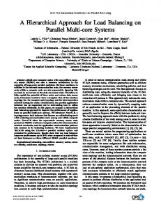
The amount of load to be transferred from node i to node j is given by δij. The load balancing schedule should make the load on each ECU equal to the average load Lavg. The conjugate Gradient Algorithm was used to calculate the average load on each ECU. Fig 1 shows the graph of five interconnected ECUs.. Let the average degree of the graph be 2.4 Each ECU has a work load li associated with it. The number in the bracket indicates the percentage CPU utilization, which is the load on each ECU.
Figure 1. Graph of five ECUs with average degree=2.4.
The Laplacian matrix of the graph is given by
PROPOSED MATHEMATICAL APPROACH TO LOAD BALANCING
An ECU is expected to perform a predefined job. When the complexity of the function scheduled on a single ECU increases, an 8 bit CPU must be replaced by 16 bit CPU. As functionality increases, an 8 bit CPU suffices the requirement, as far as I/O operations are © 2009 ACADEMY PUBLISHER
/N
2
0
-1
-1
0
λ1
18.2
0
2
-1
-1
0
λ2
11.2
-1
-1
3
0
-1
λ3
-17.8
-1
-1
0
3
-1
λ4
-11.8
0
0
-1
-1
2
λ5
0.2
λ1=9+λ5. λ3=-1.1+λ5
λ2=5.5+λ5 λ4=0.9+λ5
λ5=λ5
78
LETTERS International Journal of Recent Trends in Engineering, Vol 2, No. 6, November 2009 From the matrix, it is found that for proper load sharing, the amount of load to be transferred between the nodes is as follows δ14=λ1-λ4, δ13=λ1-λ3, δ24=λ2-λ4, δ23=λ2-λ3, δ31=λ3-λ1, δ32=λ3-λ2, δ35=λ3-λ5, δ42=λ4-λ2, δ45=λ4-λ5, δ45=λ4-λ5, δ54= - δ45 V.
towards saving cost, reducing complexity and possibility of adding new features using existing computing resources available across ECUs in the vehicle. Advances in VLSI technology like advent of multi-core processors make it possible to provide enough computing resources on a single ECU to integrate multiple functionalities. REFERENCES
RESULTS AND DISCUSSIONS
[1] Christian Wewetzer, Klaus Lamberg and Rainer Otterbach, “Creating Test Patterns for Model-based Development of Automotive Software”, SAE International 2006. [2]. Paolo Giusto , Jean-Yves Brunel, Alberto Ferrari, Eliane Fourgeau, Luciano Lavagno, Alberto Sangiovanni-Vincentelli, “Automotive Virtual Integration Platforms: Why’s, What’s, and How’s”, IEEE International Conference on Computer Design: VLSI in Computers and Processors (ICCD’02). [3]. Karen D. Devine 1, Erik G. Boman, Robert T. Heaphy, Bruce A. Hendrickson, “New Challenges in Dynamic Load Balancing”, Preprint submitted to Elsevier Science. [4]. Nicolas Navet, Francoise Simonot-Lion, “ Automotive Embedded Systems Handbook”, CRC Press. [5]. Rajeshwari Hegde, K S Gurumurthy, “ Model Based Approach for the Integration of ECUs”, ICCSE, World Congress on Engineering 2008, U.K. [6]. Daehyun Kum, Gwang-Min Park, Seonghun Lee, Wooyoung Jung, “AUTOSAR Migration from Existing Automotive Software”, International Conference on Control, Automation and Systems 2008, Korea. [7]. Meinhard Erben, Wolf Günther,Tobias Sedlmeier, “The Impact of Automotive Standardization to Liability Risks Arising from Defective Software, Especially under European Law”, SAE International Journal of Passenger Cars- Electronic and Electrical Systems April 2009 vol. 1 no. 1 38-44. [8]. Helmut Fennel, Stefan Bunzel, Harald Heinecke, Jürgen Bielefeld, Simon Fürst, Klaus-Peter Schnelle, Walter Grote, Nico Maldener, Thomas Weber, Florian Wohlgemuth, Jens Ruh, Lennart Lundh, Tomas Sandén, Peter Heitkämper, Robert Rimkus, Jean Leflour, Alain Gilberg, Ulrich Virnich, Stefan Voget, Kenji Nishikawa, Kazuhiro Kajio, Klaus Lange, Thomas Scharnhorst, Bernd Kunkel, “Achievements and Exploitation of the AUTOSAR Development Partnership”, CTEA 2006. [9]. Arndt Bode, “Load Balancing In Distributed Memory Multiprocessors”, Invited paper, IEEE 1991. [10] Can Static Load Balancing Algorithms Be Appropriate in a Dynamic Setting? http://www.dl.ac.uk/TCSC/Staff/Hu_Y_F/MEETING/TALKS/hendrick son.ps.gz. [11]. Cheng-Zhong XU amd Francis C.M. Lau, “Iterative Dynamic load balancing in multicomputers”, Journal of Operation Research Society, Vol. 45, No. 7, July 1994, pp,786-796. [12]. Y. F. Hu, R. J. Blake and D. R. Emerson, An Optimal Migration Algorithm for Dynamic Load Balancing, Concurrency-Practice and Experience, Journal Article, 1998. [13]. AUTOSAR, www.eu.necel.com. [14]. Ralf Diekmann, Burkhard Monien, Robert Preis, “ Load Balancing Strategies for Distributed Memory Machines”, In:F Karsch, H.Satz(ed.): Multi-Scale Phenomena and their Simulation, World Scientific, 1997 (to appear). [15]. Y F Hu, R J Blake, “An optimal dynamic load balancing Algorithm”, citeseer.ist.psu.edu/121199.html, 1995. [16]. Y F Hu, R J Blake, D. R. Emerson, “ An Optimal Migration Algorithm for Load balancing”, Concurrency-Practice and Experience, 1998. [17]. Antal Rajnak, Ajay Kumar, “Computer-aided Architecture Design & Optimized Implementation of Distributed Automotive EE Systems”, DAC 2007.
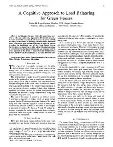
The fig 2 shows the load on each ECU before and after load balancing. The average degree of the graph is 2.4. The load balancing algorithm converged after three iterations. The simulation was done using MATLAB. 75 Actual data 1st iteration 2nd iteration 3rd iteration
70
Load on each ECU
65 60 55 50 45 40 35
1
1.5
2
2.5 3 3.5 Number of ECUs
4
4.5
5
Figure 2:Average load vs number of ECUs (Average degree of the graph=2.4)
The graph was plotted on the basis of the amount of load, which is the amount of CPU utilization transferred from one node to another. Two nodes representing two ECUs get connected only on exchange of load. The load on each ECU was generated randomly. It was observed from the simulation result, that the Conjugate Gradient algorithm converged after three iterations with the average degree of the graph being 2.4. It was observed that, as the average degree of the graph increases, number of iterations required to converge also increases. This method of load balancing does not consider the communication cost of transferring the load from overloaded ECU to under loaded ECU. This method focuses only on the load transfer between ECUs on the basis of CPU utilization. VI.
CONCLUSION
The present work was taken up to have a formal look at Load balancing in Multi ECU Configuration, on the basis of CPU utilization. The above method does not consider the communication overhead required to migrate the load from one ECU to another. The load balancing approach reduces the complexity of the automotive system by equally distributing the load across different ECUs. This mechanism in automotives eases the ECU integration by reducing the total number of ECUs. Reduction in number of ECUs provides huge opportunity © 2009 ACADEMY PUBLISHER
79