Moreover, the architecture for multiple pattern matching is given with some ... In section 2, we go over the related works in pattern matching. In section. 3, we analyze ... logics in FPGAs. The key issue is .... which is the basis of our solution. IV.
A Memory Efficient Multiple Pattern Matching Architecture for Network Security Tian Song, Wei Zhang
Dongsheng Wang, Yibo Xue
Dept. of Computer Science and Technology Tsinghua University Beijing, P.R.China {songt02, zhwei02}@mails.tsinghua.edu.cn
Microprocessor and SoC Tech. R&D Center Tsinghua University Beijing, P.R.China {wds, yiboxue}@tsinghua.edu.cn
Abstract—Pattern matching is one of the most important components for the content inspection based applications of network security, and it requires well designed algorithms and architectures to keep up with the increasing network speed. For most of the solutions, AC and its derivative algorithms are widely used. They are based on the DFA model but utilize large amount of memory because of so many transition rules. An algorithm, called ACC, is presented in this paper for multiple pattern matching. It uses a novel model, namely cached deterministic finite automate (CDFA). In ACC, by using CDFA, only 4.1% transition rules for ClamAV (20.8% for Snort) are needed to represent the same function using DFA built by AC. This paper also proposes a new scheme named next-state addressing (NSA) to store and access transition rules of DFA in memory. Using this method, transition rules can be efficiently stored and directly accessed. Finally the architecture for multiple pattern matching is optimized by several approaches. Experiments show our architecture can achieve matching speed faster than 10Gbps with very efficient memory utilization, i.e., 81KB memory for 1.8K Snort rules with total 29K characters, and 9.5MB memory for 50K ClamAV rules with total 4.44M characters. A single architecture is memory efficient for large pattern set, and it is possible to support more than 10M patterns with at most half amount of the memory utilization compared to the state-of-the-art architectures. Keywords-pattern matching; string matching; virus scanning; intrusion detection
I. INTRODUCTION Computer network has become an essential part of our daily life. To ensure the safety of network, various network security measures are taken. Being the most widely deployed one, firewall ensures information transfer from trusted sources to destinations by inspecting the packet headers. However, numerous malicious contents, such as intrusions, viruses, spam, spyware, can still outplay firewalls by hiding themselves in the payload of packets. Consequently content inspection based applications emerged, including intrusion detection and prevention systems (IDS/IPS), virus scanners, spam filters, content security management appliance, and et al. Furthermore, unified threat management system (UTM) is introduced to incorporate all the functionalities. For these applications, one of the most challenging tasks is to improve inspecting speed and capacity to catch up with the rapid growth of network speed.
This work is supported by National Natural Science Foundation of China (No.60673145).
As one of the basic operations, multiple pattern matching is the performance bottleneck of many content inspection or deep packet inspection based applications. Pattern matching architectures for network intrusion detection systems have emerged in the past few years, which can handle thousands of patterns. A clear trend is that pattern sets of applications become larger and larger. For example, tens of thousands of signatures are already common in anti-virus scanners. In our work, a pattern matching architecture for tens of thousands of signatures is proposed. The first idea is to use an algorithm based on a novel model, namely cached DFA (CDFA), to express the pattern set more efficiently. The algorithm is called ACC. The second idea, next state addressing (NSA), is to store transition rules of finite automata using less memory. It is achieved by taking states as addresses and employing feature of the state acting as the next state in DFA or CDFA. These two ideas both increase the memory efficiency. Moreover, the architecture for multiple pattern matching is given with some optimizations for reducing critical path and the memory utilization. In conclusion, the contributions of this paper can be summarized as follows: • We present an algorithm based on CDFA, which extends DFA by associating some memory as cache. Compared to AC, ACC can reduce the number of transition rules in Snort and ClamAV to 20.8% and 4.1% respectively. • We present a novel scheme named next-state addressing (NSA) to store and access transition rules in memory. Some analyses show that NSA is memory efficient in usual cases. • We give several optimizations to shorten critical path and increase the memory utilization efficiency. The methods include fine grain multithreading-like pipelining, entry combination, set-associative policy etc. • Our approach inherits all the merits of DFA, such as deterministic matching performance, dynamic update. It is suitable for implementation on FPGAs and ASICs. The rest of the paper is organized as follows. In section 2, we go over the related works in pattern matching. In section 3, we analyze DFA model and explain its limitations. Then in section 4, we introduce CDFA, our algorithm ACC, NSA scheme and our architecture in details. Further optimizations
and results about critical path and memory usage are given in Considered the different functions, all transition rules section 5. Finally conclusions are drawn in section 6. can be classified into four categories: basic transitions, cross transitions, failure transitions and restartable transitions. II. RELATED WORKS • Basic transitions are the ones that successfully accept Many pattern or string matching architectures have been pattern set from the beginning state(S0), such as the one proposed in recent years for network security. Most of the numbered 1-5 in figure 1. They act as the backbone of the researches focus on pattern matching issue for network DFA. All states can be decided after the basic transitions intrusion detection and prevention system (NIDS/NIPS), in are generated. which pattern set consists of about three thousand patterns. • Cross transitions are the ones that transfer from one The early researches of pattern matching architecture are pattern to another or one part to another part within one based on programmable logics in FPGAs. The key issue is pattern. They are required because the sub-pattern that how to efficiently map patterns to the circuits of logic on one state accept and represent may be the same as the FPGAs [2,3,4,6,11,21]. Among the related works, I. Sourdis prefix of other patterns or this pattern itself, such as [11] and C.R.Clark [4] present their architectures to give transition No.6. several methods to efficiently map patterns on FPGAs. • Restartable transitions transfer current state to the next At the same time, some RAM based architectures for states of S0. They restart the procedure of matching of ASICs were also proposed using Aho-Corasick [19] like DFA, such as transition No.7-10. algorithms [1,7,9,10,12,14]. For those architectures, pattern • Failure transitions transfer current state to S0, which stand sets are stored in RAM other than logics. The main issue is for failure in stepping forward of the matching. In figure to use less memory to effectively support bigger pattern set 1, 11-16 belong to this category. with deterministic high frequency. Lin Tan [12] developed Because more transitions will consume more memory in an approach to split the state machines into tiny ones for less AC like algorithms, optimizations are proposed to reduce memory. Jan v. Lunteren [1] gave an architecture based on the number of transitions. B-FSM with string set partitioning to achieve the goal. Although the four categories are not explicitly proposed, Some other optimization methods were also proposed by Jan v. Lunteren[1] successfully reduced all the failure and using bloom filter [7] and TCAM [5]. restartable transitions to at most 256 transitions using the Besides NIDS/NIPS, some other network applications priority approach. He set failure and restartable transitions a also require pattern matching, such as anti-virus scanners priority of 0 and 1 respectively. Then the natural feature of and spam filters. These applications may have much bigger lower priority can exploit “don’t care” technique, which pattern set than the one in NIDS/NIPS. In this paper we aim does not care the accepting characters using lower priority, at exploring an efficient pattern matching architecture on so that all failure transitions are combined to one transition ASICs for most content or deep packet inspection based (lowest priority with “don’t care”). Similarly, restartable security applications. The pattern set ranges from tens of transitions are combined to 256 transitions (lower priority thousands to hundreds of thousands. with “don’t care”). Without distinguishing cross transitions and basic transitions, he set both of them priority of 2. III. PROBLEM ANALYSES In our work, the motivation is to reduce the cross Pattern matching has different meanings in different transitions, because they outnumber all the other ones. Cross context. In our work, patterns can be found anywhere in the transitions represent common sub-patterns, and we cannot input data. Typically Aho-Corasick(AC) and its derivative efficiently avoid them by selecting pattern set. A natural algorithms are used. These algorithms can build a DFA method is to partition the pattern set to many unrelated from pattern set and run it in step for searching. In this smaller ones, handled by individual DFAs, so as to avoid section, we give analyses about the inefficiency of DFA of common sub-patterns. Here we give some statistics based on AC and present the motivation of our approaches. Snort and ClamAV rules to evaluate this natural method. Figure 1 shows the DFA of AC for accepting pattern set Snort[16] is an open source network intrusion detection of {SEC, SSH}. There are 6 states and 16 transitions in it. system consisting of thousands of patterns. We use one 12 pattern set of 2005, which has about 3000 patterns. After !S 8 S 11 eliminating duplicated ones, there are 1785 different 7 !C & !S s2 3 C s3 patterns left. It stands for a moderate set. S 2 E ClamAV [17] is an open source anti-virus system with a S 1 S1 s0 16 6 E daily updated signature set. The set of Oct. 8, 2006 is used !S & !E 4 S !S 15 H with about 50000 signatures. After eliminating duplicated S s4 5 s5 !H&!S&!E 9 ones, there are 49644 patterns left. It stands for a large set. 13 S 10 In our statistics, a pattern set is divided into smaller ones 14 !S by the method of even partition on the number of patterns. Legend Input character S For example, a pattern set with 256 patterns can be divided Pattern Set 4 into two smaller sets with 128 patterns each. During the {SEC,SSH} transition Serial number process of partitioning, no optimization is used. Because Figure 1. DFA of AC for accepting pattern set {SEC, SSH}
Input Character
Input Character State Register
Tran-rules Memory &Tran-rules Selector
Tran-rules Memory &Tran-rules Selector
(a)
(a)
(b)
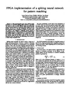
Figure 2. Statistics of basic and cross transitions
State Register
Cache
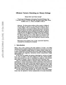
(b) Figure 5. DFA and CDFA
From our research, we believe that the reason why cross transition rules in AC like algorithms cannot be efficiently optimized or eliminated is because of their basic model, i.e., DFA. To improve the efficiency, a more suitable basic model for pattern matching algorithms is needed. In our work, a novel model, namely cached DFA, is proposed, which is the basis of our solution. IV.
Figure 3. 1-step and n-step cross transitions
(a)
(b)
Figure 4. Statistics of 1-step and n-step cross transitions
failure and restartable transitions can be optimized to at most 256 [1], they are not counted in statistics. In figure 2, (a) and (b) show the trend of the number of transitions(“tran-rules” for short) in different categories in Snort and ClamAV set respectively. The number of subsets is named “subset number”. For subsets, the results are the sum of all related ones in the subsets. As we can see, the total number of transitions is changing with the number of cross ones. The more subsets a pattern set has, the less total transitions it is. However, for larger set, such as ClamAV, the method of partition still results in huge cross transitions. To further the understanding of cross transitions, they are classified into two types: 1-step cross transition and nstep (n>1) cross transition, shown in figure 3 for example. Figure 3 shows the DFA of AC for pattern set {SEC, SSH, ECC}. Transition 1 is a 1-step cross transition because one-character prefix of “SEC” matches substring of “SSH”. Transition 2 is an n-step cross transition because twocharacter prefix of “ECC” matches substring of “SEC”. Taking real patterns as example, figure 4 (a) and (b) show respectively the number of 1-step and n-step cross transitions. Obviously, the number of 1-step is the major part of all cross transitions, even of all transitions. The proportion of 1-step becomes larger when the pattern set becomes larger.
OUR APPROACH
A. Cached Deterministic Finite Automata As illustrated in figure 5(a), the traditional DFA is a simple and concise model. The transitions are stored in transition rules (“tran-rules”) memory and accessed by tranrules selector. The next state is only determined by input character and current state (stored in state register). We extend the traditional DFA model by using certain number of registers as cache (only one register is used in this work), as figure 5 (b) shows. Then some information can be temporarily stored and employed. The new model is named as cached DFA (CDFA), because the cache acts as an internal structure and is handled by CDFA automatically, similar to the cache in memory systems. With cached states, CDFA extends DFA with the capability of temporary memory. The next state in CDFA is determined not only by input character and current state but also the cached states, which is the main difference between DFA and CDFA. A CDFA is a 7-tuple, {K , Σ, s0 , F , N , δ ,θ } , concluding • •
A finite set of states, K A finite input character set, called “alphabet”, ∑
•
A start state, s0
• • • •
A set of accepting states, F ⊆ K The number of cache size, N, in this paper N=1 A transition function that , δ : K × K N ×Σ → K A caching function, θ : K × Σ → K
For CDFA, the next state is determined by current state, current input and N cache states, which is described by transition function. The N cache states are handled by the policy of caching function. Another important difference in CDFA from DFA is that caching function and transition function are both userdefined. It is understandable if we take various policies for caching in memory system as an example.
B. Pattern Matching Algorithm based on CDFA AC and its derivative algorithms are all based on DFA. Here we propose a multiple pattern matching algorithm based on CDFA, called AC-CDFA (ACC). The process of ACC is similar to AC except the operation of CDFA. It has all the merits of AC and produces much less transitions. The basic idea of ACC is to dynamically generate and accept all 1-step cross transitions by using CDFA, so that 1step ones are no longer stored in memory. That is, all 1-step cross transitions in DFA are eliminated in CDFA. As the major part is eliminated, ACC can save much memory space. At the preprocessing stage, while CDFA is built from a pattern set, only basic transitions and n-step cross transitions called c-trans in original DFA are generated At the matching stage, CDFA accepts input characters using transition function and caching function. Transition function δ , which is used to generate next state, is defined as follows. The next state is first determined by input character and current state. If there is no corresponding c-trans, the next state is then determined by input character and cached state (in our algorithm, only one cached state is used, i.e. N=1). Caching function θ , which is used to cache state in CDFA, is defined as follows. If the beginning state s0 accepts current character and step to the state sj by c-trans, sj is stored as cache state. Otherwise, s0 is stored as cache state. Actually, in ACC, not only 1-step cross transitions but also failure and restartable transitions can be dynamically generated and never required to store. At the matching stage, the “store-to-cache” operation is always performed at every cycle. An example of this process is given in figure 6 to show our algorithm. In figure 6 (a), an original DFA model for the pattern set {cross, slice} is given, in which all failure and restartable transitions are omitted for concision. Transitions numbered 1-3 are 1-step cross transitions. CDFA model is built in figure 6 (b) for ACC which only consists of basic transitions (and n-step cross transitions if there are) in original DFA. At s6
s
l
s7
s0
i
s8
1
s1
c
r
c s9 e s10 r 2
l
3
l
s2 o s3 s4 s5 s s
(a) DFA model with basic and 1-step cross transitions
cycle 1
cycle 2
$Cache
S6
cycle 3
S6 cycle 4
s1 r s2 o s3 s s4 s s5
s0
cycle 1 2 3 4 5 6 7 8
s
input c
s6
l s7 i s8 c
cycle 5
cycle 6
current state
cycle 7
s10
cycle 8
o
c-trans
s
input S0
c-trans c-trans
l
i
c
e
high
input cached state
s9 e
r
low
high low
Priority
c
next state
Priority
cycle 0
store to cache
(b) CDFA and the process to accept “croslice” Figure 6. DFA and CDFA model for pattern set {cross, slice}
the same time, a cache is added and the function of state transfer is changed. The process to accept the input “croslice” is taken as an example. When a character comes, the next state is firstly determined by current c-trans if there is a proper one, such as S1, S2. If no c-trans are found, cached state is fetched and used as “current state” to find proper c-trans, and then next state can be determined. In cycle 5, there are no c-trans for “S4” to accept character “l”. Then cached state “S6” is fetched, and there is one transition from “S6” to “S7” by accepting “l”, so next state is “S7”. In ACC, ONE state cache is used to eliminate 1-step cross transitions. Theoretically, N state caches can be used in CDFA to eliminate all cross transitions from 1-step to Nstep. Because 1-step cross transitions are the major part, our work processes them first. In appendix, a proof is given to show that our algorithm and AC algorithm are equivalent. With ACC, all 1-step cross transitions in figure 4 can be eliminated. As a result, 95.9% total transition rules are released for ClamAV set, and 79.2% for Snort set. For cross transitions, 96.9% are released for ClamAV set, and 89.9% for Snort set. In above statistics, failure and restartable transitions are excluded, because they are easy to control within 256 transition rules by the priority approach. C. Next State Addressing Scheme Our algorithm can be implmented into both software and hardware solutions for multiple pattern matching. In our work, we apply it to hardware solution. When AC like algorithms are used in hardware solutions, another important issue is how to efficiently store and access transitions in memory. Here, we present another idea, namely next state addressing (NSA), to handle this issue. There are two methods to store and access transitions of DFA in other papers, using CAM and hashing. Content-addressable memory (CAM) is a special type of computer memory, which can compare the input internally and output the address of matched content in parallel. When the transitions are stored in CAM, the address can be output in one cycle and the next state can be found together with a SRAM. [23] CAMs are good but they consume lots of chip area, power and cost, because of their internal architectures. Hashing uses common memory. The address of memory for transition rules is computed from current state and input character. Then some candidate items are back for checking. BART[1] and other hashing methods are relatively chip-area efficient, but inevitably result in conflicts in hashing item. The main purpose of next state addressing (NSA) is to precisely address the proper transition rule for the current state with common memory. The essence of states in finite automata is uniquely indexed, which help specify transition rules. The only useful information is the character state accepts. NSA store characters only. Compared with other methods, it stores transition rules more efficiently. The basic idea of NSA is to exploit the current state in order to precisely calculate one possible next state, and take the next state as the address to access the memory of transition rules. After finding the transition, it is verified by comparing the incoming character and the accessed one.
Linear trie
S1
r
Input character
o S3 s S4 s S5 S2
Zero check
ITT Input Translation Table
1
Figure 7. Linear trie in DFA or CDFA
sj
si sl
color : 1 color : 2
0x00 0x01 j-i k-i l-k Ø
sk
Dual MUX
next state
(address) 0x00 0x01
=
C M P
(character) (color) (address) (next state) (color)
0xff
0x01
0x01
=: left ?: right
+
color
0x00
state register
color
cross tran
color register
0: right others: left
state
i S7 n basic tran i
MUX
…
… character
0xFF
0xea
sm 0xFF Ø
TRM-1
TRM-0
0x01 0x00
Figure 9. Overall architecture of NSA scheme
To calculate next state for colored states, a structure named input translation table (ITT) is used as figure 8 shows. Each color corresponds to one entry of ITT and each entry has … … … … … 256 items which correspond to 256 input characters. Each Ø Ø Ø color : n item stores the result of subtracting next state number from current state. By state color and input character, next state of Input Translation Table (ITT) colored state can be calculated by looking up ITT table. In Figure 8. Details of ITT ITT table, Ø means null value, which is actually invalid. The reason why next (future) state can be used as The next state is calculated differently for colored and nonaddress is based on two observations. First, after 1-step colored state using the following equation. cross transitions (96.9% of all cross transitions for ClamAV, current _ state +1, if current _ color = 0 next _ state = and 89.9% for Snort) are eliminated, there are a lot of linear current _ state + itt ( input , current _ color ), if current _ color! = 0 trie in CDFA, as shown in figure 7. Each state in the linear Besides the basic idea of NSA, NSA scheme for storing trie has only one next state. By orderly labeling the states in linear trie, next state can be calculated from the current state. and accessing transitions consists of an optimization. That is, The second observation is that, for each state, the input a standalone small memory is used to store all transitions characters of all “incoming” transitions are the same no from S0, which is named as transition rules’ memory zero matter how many and what kind of they are. That is, each (TRM-0). TRM0 is a lookup table structure that has 256 state accepts only one character when it is regarded as “next entries indexed by all possible input characters. Each entry state” of one transition. For example, in figure 7, S7 only stores the state after S0 accepting the addressed character or S0. Details can be found in [1]. The other transitions are accepts character “i” no matter what types of transition. NSA is proposed based on the two above observations. stored in transition rules’ memory 1 (TRM-1). The overall architecture of NSA scheme is shown in To implement the method, states of CDFA (or DFA) should be specially numbered. During compilation (CDFA or DFA figure 9. Some trivial details are omitted. In the NSA scheme, the next state is firstly calculated. is built from a pattern set), states are labeled by using the Then the TRM-1 is secondly accessed via next state as following algorithm. • The start state of CDFA (or DFA) is numbered as S0. address. Then the result is compared with the input • If a state has only one next state, the next state is character. If characters are the same, CDFA steps forward and the next state and the color are turned into current ones. numbered one bigger than the current one. • If a state has several next states, depth-first algorithm If they are different, the output state and color of TRM-0 are set to the current ones. It means that failure or restartable is used to number the next states. To use next states as addresses, the address (next state) transition is performed. should be calculated by current state and input. For the D. Our Pattern Matching Architecture states in the linear trie, the next state can be calculated by Our pattern matching architecture incorporates our ACC adding one. However, there are some states that have algorithm based on CDFA (for fewer transitions) and NSA several next states. (They are fewer in CDFA because of scheme (for effectively storing transitions), as shown in fewer transitions.) To handle this situation, those states are figure 10 (Some trivial details are omitted for concision). individually colored. The color can be considered as the In our architecture, ITT and TRM-1 are designed to use second number of the state. We use the word “color” just for dual port memory, so that state register and state cache can avoiding the confusion of state number. access them in parallel. (Single port memory can also be m-k
Input character
s0
0x65
s1 ITT (dual port)
out-port-1
in-port-1
1
1
MUX 0: right others: left
MUX
color register 0: right state register others: left
CMP
2 1
Tri MUX
+
123 123
next state
(next state) (color)rst
0x01 color
0xea
TRM-1 (dual port)
out-port-1 out-port-2
color
TRM-0 color
…
0x65 0x63
0x6f
s4
0x63
s6 0x6f
0x61
s7
s2
s0 0x63
0x6c
s5
0x65
s8
s6
0x6f
s3
s4
0x63 0x6f
s7
Ø
ITT
0x61
Color 1
…
Ø
…
Ø
…
1
…
5
…
Ø
…
Color 2
…
1
…
Ø
…
Ø
…
Ø
…
2
…
Color 3 Color 4
…
Ø
…
3
…
1
…
Ø
…
Ø
…
…
Ø
…
Ø
…
Ø
…
Ø
…
-3
…
0x63
0x65
0x6c
0x6f
state
(character) (color) rpt
state
0x00
color
state
(address)
(address)
s1
s8
s3
state cache
CMP
next state in-port-1
color cache
+
= =
0x61
s2
0x65
s5
0x63
0x63
in-port-2 out-port-2
0x6c
ITT
0x61
Color 1
…
1
…
3
…
1
…
5
…
Color 2
…
Ø
…
Ø
…
Ø
…
Ø
…
color char char
in-port-2
Figure 10. Our pattern matching architecture
0x6c
0x65
0x63
0x6f
2 -3
… …
(a) An example
used regardless of parallelism accessing.) One Tri-MUX is used as the function for priority switching. It accepts three sets of inputs (three colors and three states) and outputs one color and state based on two control signals. The control signals are results of two CMP (compare) units, numbered as “1” and “2”. The function of Tri-MUX is ( state, color ,"1"), if "1" = equal , high _ priority output ( state, color ) = ( state, color ,"2"), if "2" = equal , medium _ priority ( state, color ,"3"), others, low _ priority
When an input character arrives, register (state and color) and cache (state and color) both start to access TRM-1 in (b) The algorithm for entry combination parallel. At the same time, TRM-0 is accessed for failure and restartable transitions. Three possible next states and Figure 11. Entry combination for ITT optimization their corresponding colors are generated and sent to TriMUX component. It outputs only one state and its color to Given two colors Ci and Cj , the kth items of their entries update state and color registers respectively. The update drives CDFA stepping forward. The caches (state and color) are designated as Ci[k ] and Cj[k ] , and the corresponding states are S (Ci) and S (Cj ) . Acp( S ) represents the character are directly overwritten by the outputs of TRM-0. which triggers the transition to S. The algorithm for judging V. OPTIMIZATIONS AND RESULTS whether they can be combined is listed in figure 11(b). For example, in figure 11(a), the initial ITT has 4 entries A. ITT Optimizations corresponding to the 4 colored states of CDFA. After In the original design, one colored state is assigned to an combination, only 2 colors are left. entry of ITT, with 256 items. Most colored states have only For each entry of ITT, the algorithm tries to combine it a few next states, and most items of their corresponding with the previous ones. In figure 11(a), color “2” is entry of ITT are set to Ø. To effectively utilize ITT’s space, evaluated whether it can be combined with color “1” first. It two optimizations (entry combination and set-associative turns out that, the two can be combined and color “1” is strategy) are proposed in this section. updated. Then color “3” is evaluated with color “1”. 1) Entry Combination The basic idea of entry combination is to combine some entries into one. Two entries can be combined if and only if all items of the same column have no conflicts. The conflicts may occur in two cases. (1) As two corresponding items have different non-Ø values, conflict (resource conflict) exists. (2) As the non-Ø item overwrites the Ø one, the next state of written entry is the state calculated by adding the non-zero item. If that state accepts the same character, it leads to conflict, called overwriting conflict.
2) Set-associative Strategy In figure 11(a), although color “4” just uses one item, it cannot be combined with color “2”, because color “2” has different value of item “0x6f”. To address this issue, a method of set associativity is presented, which is similar to the one in cache system of micro-architecture. For N-way set-associative, there are 256/N sets. The qth item of pth set corresponds to column( p, q) , and the content of color Ci is Ci[column( p, q)] . For two colors Ci and Cj , the algorithm judging whether they can be combined with set-associative strategy is shown in figure 12(b).
TABLE I.
input char
Architectures Set 1 Color 1
Set 2
Set 3
Set 4
…
Ø
tg
1
tg …
3
tg
1
tg …
Ø
tg
5
tg …
2
tg
…
Ø
tg
Ø
tg …
Ø
tg
Ø
tg …
Ø
tg
Ø
tg …
Ø
tg
-3 tg Ø
…
tg …
tg color tag input tag color tag input tag 1 bit 1 bit 1 bit 1 bit
3
1
MUX
CMP
CMP
Encoder
AND
Input tag 1 bit
character color tag color rpt 1 bit 8 bits new column
TRM-2
Failure
data
2-way set associative
ITT
(a) An example for 2-way set associative ITT
ACC with NSA
2-way 4-way 8-way
B-FSM [1] Bitmap compression [15] Path compression [15]
COMPARISON OF MEMORY USAGE FOR SNORT SET
4 8 16 mem/char* 1785 patterns with 29.0K characters 256KB 181 168 151 6.2B 163KB 123 115 106 4.2B 129KB 97 87 81 3.3B 1.5K patterns with 25.2K characters 188 120 92 7.4B N/A 2 subsets
2.8MB
154B
1.1MB
60B
*: Mem/char column is calculated for 4 subsets (shaded) only.
number of transition rule is s. The memory requirement of TRM is (in bytes)
M TRM ≈ M TRM −1 ≈ s × (1 + log 2 c ' / 8 + log 2 a / 8) The memory requirement of ITT (in bytes) is, (one more sign bit for negative value)
M ITT = 32 × c '× ( log 2 s + 1 + 2 × log 2 a ) Therefore, the memory requirement for each transition rule is approximately M tran = 1 + 0.125 × ( log2 a + log2 c ') + 32 × c '× ( log2 s + 1 + 2 × log2 a) / s
(b) The algorithm for set associativity Figure 12. 2-way set associative strategy
Two entries can be combined by set-associative strategy if and only if all items of the same set have no conflicts. The conflict may occur only when all items of any set have more than N non-Ø values. An example for 2-way set associative strategy is shown in figure 12(a). Similar to traditional set-associativity in memory system, tag is attached to each item. The tag has two fields: color tag and input tag, which represent the color and input index before set-associative strategy respectively. B.
Analyses and Results of Memory Requirement In CDFA, all the 1-step cross transitions, failure and restartable transitions are eliminated, which are the major part of total ones. Thus ACC based on CDFA is memory efficient. In this section, we focus on analyzing memory requirements of NSA scheme. Suppose that the given pattern set has n patterns with m characters. The CDFA model has s states, including c colored states. After ITT optimization, there are c’ different colors, with α -way set associative strategy. Because CDFA has eliminated all 1-step cross transitions (more than 90% of all cross ones), all cross ones can be regarded as eliminated. Thus the number of total transition rules is approximately equal to the number of basic transitions. As each state except S0 corresponds to one basic transition, the total
The traditional ideal case is that each transition rule consists of input and one state, requiring M ideal = 1 + log 2 s Thus compared to the ideal cases, approximately if s > 32 × c ' , NSA scheme will be more efficient. This is very common after two steps of optimizations for ITT. The result of memory utilization for Snort pattern set is listed in table 1 compared with other methods. In table 1, our architecture uses nearly constant memory from 4 subsets to 32 subsets. This implies that with CDFA, pattern set partitioning is no longer the key to reduce memory usage, compared to other architectures. For the same subset, ACC algorithm requires less memory than other architectures, such as B-FSM scheme with optimized partitioning. Table 2 gives the memory usage for ClamAV pattern set. The similar features are concluded, and at least 9.5MB memory is required for about 50K patterns totaling 4.44M characters. When our architecture is compared with others, two facts should be taken into account. The first one is that SDRAM or SRAM are used in our method other than CAM or TCAM. The other one is that our results are given in the fewer number of subsets. This means our method is the most straightforward way to handle larger pattern set. To explain the overhead of more subsets, our architecture is implemented in verilog. The verified HDL architecture is synthesized with a 0.18µm standard cell library using Synopsys tools. Synthesized results about chip area are shown in figure 13. It is obvious that more subsets can result in more chip area, and the conclusion is fit for other architectures.
TABLE II.
CDFA 2-way 4-way 8-way
TABLE III.
MEMORY USAGE FOR CLAMAV PATTERN SET
32subsets
26.8MB 21.6MB 18.7MB
64 19.9 16.6 14.8
128 16.3 13.8 12.4
256 13.9 11.7 10.8
512 12.0 10.3 9.5
Mem/char*
6.0B 4.9B 4.2B
*: Mem/char column is calculated for 32 subsets (shaded) only.
COMPARISON OF CRITICAL PATH DELAY
Architectures ACC with NSA
No pipeline 2 pipelines more pipelines FSM [12]
Bit Split B-FSM [1] Cho-MSmith [10] Predec CAMs [11]
Bloom Filter [7] Decoder NFA [4] USC Unary [21] Compressed DFA[22]
Critical path delay (ns)
Matching speed (Gbps)
Notes (1 byte/cycle input)
1.65 1.18 0.85
6.1 8.5 11.7
0.18µm tech
N/A N/A 1.12 N/A N/A N/A N/A N/A
0.8~1.0 7.14 2.68 0.5 2.0 2.1 1~10
8.4~10.0
simulator FPGA 0.18µm tech
FPGA FPGA FPGA FPGA calculated
Figure 13. Chip area of Snort with 8-way set associativity
C. Critical Path Optimization In our architecture, two larger memories (ITT and TRM) are accessed in one cycle respectively. To achieve high frequency, the critical path can be pipelined to more stages. Since next state is highly dependent on current state, pipelining becomes very challenging for single data steam, therefore we adopt the method of fine-grain multi-threading [20]. The basic idea is to concurrently fetch from different data streams on a cycle-by-cycle basis, while only one data stream is involved at each pipelining stage. Suppose that we have two pipeline stages in figure 14, two data streams are involved. On even cycles, one character from data stream A arrives and occupies the first pipeline stage. On odd cycles, one character from data stream B arrives at the first stage while the character from stream A occupies the second stage. Stream parallelism is one feature for network applications. Therefore our method of pipelining is natural and feasible. Using this method, our architecture can achieve very high throughput. Table 3 shows the comparison of our design to the others on critical path delay and throughput. The item of “more pipelines” is the longest delay in the design. The critical path is the ADD component that computes next state. It can be further optimized by using customized component. D a ta stre a m A
state re gister A colo r register A
ev en cy cle ac tive
in pu t cha ra cte r
IT T pip e lin e sta g e 1
D a ta stre a m B od d c yc le a ctive
state cac he A co lo r cache A
state registe r B color register B
Figure 15. Pattern set compiler
D. Pattern Set Compilier and Dyanmic Update Our pattern set compiler has two modes, as shown in figure 15. The first mode is building CDFA from initial pattern set and allocating memory for our architecture. The second mode is pattern update. Based on the algorithms of building CDFA and coloring states, score and suggestions are given to the pattern for update. This will help the experts of network security to define more efficient patterns (signatures) for our architecture. The pattern set compiler is implemented in C language. Only seconds are used to build CDFA for Snort and ClamAV set on a normal server. To achieve dynamic update without interrupting ongoing data matching operations, a backup CDFA architecture is used as the method of Tan and Sherwood [12].
sta te cache B
odd c yc le a ctiv e
pip e lin e sta g e 2
e ve n cy cle activ e
colo r cach e B
T R M -0 -1
Figure 14. Method of fine-grain multithreading-like pipelining
E. Regular Expression Matching In this work, we mainly focus on normal patterns such as strings and simple variations of strings. The CDFA model can also be used for multiple regular expression matching and still performed with very efficient memory utilization.
VI.
CONCLUSIONS
This paper proposes a memory efficient pattern matching architecture for all kinds of network security applications, with the size of pattern set ranging from 1K to 10M or even more. Our pattern matching algorithm, ACC, is based on a novel model, namely CDFA, which can eliminate more than 90% transitions for the applications of network security. An NSA scheme for efficiently storing and accessing transitions is proposed. Moreover, our pattern matching architecture is optimized with several approaches to achieve better performance and less memory utilization. Experiments show that only 81KB memory (SRAM or SDRAM) is needed for about 1.8K Snort rules (total 29K characters) and 9.5MB for 50K ClamAV rules (total 4.44M characters). REFERENCES [1] [2] [3]
[4] [5]
[6]
[7]
[8]
[9]
[10]
[11]
[12]
[13]
[14]
[15]
[16]
Jan van Lunteren. High-Performance Pattern-Matching for Intrusion Detection. In 25th Conference of IEEE INFOCOM, Apr. 2006 Z.K. Baker and V.K.Prasanna. Time and Area Efficient Pattern Matching on FPGAs. In 12th Annual IEEE FCCM, April 2004 Z.K. Baker and V.K.Prasanna. A Methodology for Synthesis of Efficient Intrusion Detection Systems on FPGAs. In 12th Annual IEEE FCCM, April 2004 C.R.Clark and D.E. Schimmel. Scalable Pattern Matching for high Speed Networks. In 12th Annual IEEE FCCM, April 2004 Fang Yu, R. H. Katz and T.V. Lakshman. Gigabit Rate Packet Pattern-Matching Using TCAM. In 12th Conference of IEEE ICNP, Oct. 2004 Long Bu, John A. Chandy. FPGA Based Network Intrusion Detection using Content Addressable Memories. In Conference of IEEE FPT 2004, Dec. 2004 Michael Attig, Sarang D., John Lockwook. Implementation Results of Bloom Filters for String Matching. In Conference of IEEE FPT 2004, Dec. 2004 Y. H. Cho and W. H. Mangione-Smith. Deep Packet Filter with Dedicated Logic and Read Only Memories. In 12th Annual IEEE FCCM, April 2004. Y. H. Cho and W. H. Mangione-Smith. Fast Reconfiguring Deep Packet Filter for 1+ Gigabit Network. In 13th Annual IEEE FCCM, April 2005 Y. H. Cho and W. H. Mangione-Smith. A Pattern Matching Coprocessor for Network Security. In 42nd Conference of DAC, June, 2005 I. Sourdis and D. Pnevmatikatos. Pre-decoded CAMs for Efficient and High-speed NIDS Pattern Matching. In 12th Annual IEEE FCCM, April 2004 Lin Tan, T. Sherwood. A High Throughput String Matching Architecture for Intrusion Detection and Prevention. In 32nd Annual International Symposium on Computer Architecture, ISCA, 2005 V. Paxson, K. Asanovic, S. Dharmapurikar, J. Lockwood, R. Pang, R. Sommer and N. Weaver. Rethinking Hardware Support for Network Analysis and Intrusion Prevention. In USENIX Hot Security, 2006 Hongbin Lu, K. Zheng, B. Liu, X. Zhang and Y. Liu. A MemoryEfficient Parallel String Matching Architecture for High Speed Intrusion Detection. In IEEE Journal on Selected Areas in Communications, Vol. 24, No.10. Oct. 2006 N. Tuck, T. Sherwood, B. Calder, and G. Varghese. Deterministic Memory-Efficient String Matching Algorithms for Intrusion Detection; In 23rd Conference of IEEE INFOCOM, Mar. 2004 M. Roesh. Snort – lightweight intrusion detection for Networks. In Proceedings of 13th Systems Administration Conference, Nov. 1999
[17] ClamAV: http://www.clamav.net/ (accessed on Oct. 2006) [18] B. C. Brodie, R. K. Cytron and D. E. Taylor. A Scalable Architecture for High-Throughput Regular-Expression Pattern Matching. In 33rd International Symposium on Computer Architecture, ISCA, 2006 [19] A.V. Aho and M.J. Corasick. Efficient String Matching: An aid to Bibliographic Search. Communications of the ACM, vol.18, 1975 [20] M. Loikkanen and N. Bagherzadeh. A fine-grain multithreading superscalar architecture. In proceedings of the Conference Parallel Architectures and Compilation Techniques, Oct. 1996. [21] Z.K. Baker, V. K. Prasanna. High-throughput linked-pattern matching for intrusion detection systems. In symposium on Architecture for Networking and Communications Systems (ANCS), Oct. 2005 [22] Alicherry, M. Muthuprasanna, M. Kumar, V., “High Speed Pattern Matching for Network IDS/IPS,” Proceedings of the 2006 14th IEEE International Conference on Network Protocols (ICNP'2006), Nov. 2006, pp:187-196. [23] Sensory Networks, “Apparatus and Method for Memory Efficient, Programmable, Pattern Matching Finite State Machine Hardware”, US Patent No. 7082044 B2, July 25, 2006
VII. APPENDIX Theorem 1: The Aho-Corasick algorithm and ACC algorithm in our work are equivalent. Proof: Because Aho-Corasick algorithm is based on DFA, our algorithm and AC are equivalent if and only if the DFA and CDFA from a pattern set are equivalent. Here we define DFA as a 5tuple{K , Σ, s0 , F , δ } . The transition function δ can be classified
to five sub-functions: ones,
δbasic for basic transitions, δ failure for failure
δ restart for restartable ones, δ1−cross for 1-step cross ones and
δ n −cross for n-step cross ones. CDFA is defined as a 7-tuple {K , Σ, s0 , F , N , δ ',θ } . Now we can prove that using δ ' and θ in our algorithm, the transition function δ in DFA can be represented. a S0
sk
b
sj 1-step
b
x sh
a x
c
si
sm
restartable
Figure: For proof
For basic and n-step transitions, CDFA remains the same. For 1-step cross transition, δ1− cross ( si , b) = s j , it is equal to
δ basic ( sk , b) = s j . Because the transition is 1-step cross one, in state “sh”, when character “a” comes, the state “sk” is cached in CDFA, that is θ ( sh , a) = sk . So that in state “si”, when
δ '(si , b) returns null, the low priority policy δ '(θ ( sh , a), b) = s j is performed. That is, all 1-step cross transitions in DFA can be represented using CDFA. For restartable transition in DFA, δ restart ( si , x) = sh , it can be replaced by θ ( si , x) = δ ( s0 , x) = sh . For failure transition in DFA, suppose δ failure ( si , k ) = s0 . It can be replaced by
θ (si , k ) = s0 .
Now we prove that all the transitions in DFA can be represented by transition and caching functions in CDFA. In other words, our algorithm and AC are equivalent.