version of the LEGION network [8] by segmenting a 16Ã16 pixel image. However, their design is limited to networks with an 8-neighbor connectivity and thus to a ...
FPGA implementation of a spiking neural network for pattern matching Louis-Charles Caron, Fr´ed´eric Mailhot, Jean Rouat D´epartement de g´enie e´ lectrique et g´enie informatique Universit´e de Sherbrooke, Qu´ebec, Canada Email: {l-c.caron,frederic.mailhot,jean.rouat}@usherbrooke.ca
Abstract— A field programmable gate array (FPGA) implementation of a hardware spiking neural network is presented. The system is able to realize different signal processing tasks using the synchronization of oscillatory leaky integrate and fire neurons. The use of a bit slice architecture and short, local interconnections make it adaptable to projects of various scales. The system is also designed to efficiently process groups of synchronized neurons. A fully connected network of 648 neurons and 419904 synapses is implemented on a stand-alone Xilinx XC5VSX50T FPGA, processing up to 6M spikes/s. We describe the resource usage for the whole system as well as for each functional block, and illustrate the functioning of the circuit on a simple image recognition task.
The main contribution of this work is the introduction of an HSNN which can effectively perform useful digital signal processing tasks. Just like the ODLM, the HSNN can perform image segmentation, matching, and monophonic sound source separation. The system is robust to noise and, in the case of image recognition, has properties such as insensitivity to affine transformations [2][3]. Also, the performance of our system increases with amount of network synchrony. Finally, our implementation is comparable with other HSNNs in terms of the number of implemented neurons [6] and size of segmented images [7].
I. I NTRODUCTION
II. BACKGROUND
Spiking neural networks are used to tackle a large set of signal processing problems. However, a number of situations require that the algorithm be implemented on an embedded platform. This is the case when targeting hand-held devices, which have to be small and energy efficient. In this context, a hardware implementation, on an application specific integrated circuit (ASIC) or a field programmable gate array (FPGA), can offer good performance while meeting the strict requirements of a battery powered device. Additionally, the hardware spiking neural network (HSNN) can be specifically tailored to the chosen neuron model and the specific features of the network [1]. In this paper, we present the implementation on a FPGA of an HSNN based on the Oscillatory Dynamic Link Matcher (ODLM) algorithm. The ODLM algorithm is able to accomplish image segmentation, image matching [2], and monophonic sound source separation [3]. Spike synchronization is used to bind [4][5] neurons associated with similar inputs or features. During execution, groups of synchronous neurons emerge and the presented HSNN is designed to efficiently process them. Our HSNN can be compared with certain embedded neural systems, such as the one presented by Cheung et al. [6]. Their system can simulate a network of 800 Izhikevich neurons on an FPGA, but it is not tested in a signal processing context. On the other hand, Girau and Torres-Huitzil [7] test their hardware version of the LEGION network [8] by segmenting a 16×16 pixel image. However, their design is limited to networks with an 8-neighbor connectivity and thus to a restricted set of processing tasks. The work of Vega-Pineda et al. [9] shows a performance of 250M pixels per second for a segmentation task but has a similar limitation.
The HSNN presented in this paper is a simplified version of the ODLM, a signal processing neural algorithm proposed by Pichevar and Rouat. Details regarding the ODLM are given in the following sections. A. Neuron model The ODLM uses a LIF neuron model to approximate the behavior of relaxation oscillators. In the absence of presynaptic spikes, the time evolution of a neuron’s membrane potential is governed by dvi (t) −vi (t) = + I0 , (1) dt τ where vi (t) is the membrane potential of neuron i, τ is a time constant that determines the oscillation period and I0 is an external input. When the membrane potential vi (t) reaches the threshold value v threshold , neuron i fires and its potential is reset. In order to give rise to periodic firing of a neuron defined by equation (1), the only requirement is to set the constant v threshold to a value lower than Iτ0 . When a spike is emitted, it is immediately transmitted to all post-synaptic neurons. Synapses are defined by a scalar weight, which is added to the membrane potential of the postsynaptic neurons. This instantaneous excitatory interaction leads to the quick synchronization of strongly connected neurons. B. Running the ODLM The time-driven execution of the ODLM algorithm requires alternating between two steps. The first step is the computation of the time evolution of the potential of all neurons until
Com. controller
HSNN controller W
Weight memory
...
Spiking bit
Synapse model unit
Slice / Column
Slice / Column
HSNN Slice / Column
Com.
Config. registers
Weight SB
W
Spike
P
Potential
Membrane model unit
P Spike detection
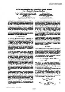
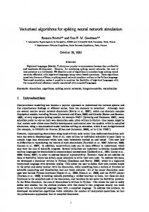
Fig. 1. High level view of the hardware spiking neural network (HSNN) and that of a slice. Left. The HSNN. The ”Com.” and ”Com. controller” take care of the communications with the host. The ”Config. registers” hold the network state information and settings from the host. The ”HSNN controller” is a finite state machine interacting with the HSNN. The HSNN uses a bit slice architecture, it is composed of several 1-bit wide column; Right. A slice. The weight memory contains all the pre-synaptic weights to the neuron instantiated by the column. The synapse model unit (SMU) adds the synaptic weights to the neurons’ potential during spike propagation. The shift register noted ”SB” holds the so called spiking bit. The SB shift register of every column is connected to its left and right neighbor to form a ring buffer. The membrane model unit (MMU), when enabled, computes the time evolution of the membrane potential. The buses entering and leaving the weight memory and MMUs are used for loading and unloading.
any neuron reaches the threshold value. When this happens, computation of the potentials is paused and a spike propagation step starts. The corresponding synaptic weights are added to the potential of the post-synaptic neurons. If this causes new spikes to happen, subsequent spike propagations will take place. Otherwise, computation of the time evolution is resumed. Once the processing is over, the relative phase of the neurons, represented by their membrane potential, is analyzed. Neuron groups are easily identifiable in the phase space and indicate neurons with similar features. III. H IGH LEVEL DESIGN
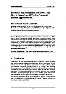
The spiking bit in the SMU of each column is updated to reflect its state at this time step: firing or not firing. All of the weights stored in the weight memories will then be read as the spiking bits will cycle through the whole network. The spiking bits are used to activate the SMUs when the weight read from the memory is to be added to a neuron’s potential. Since each column initially stores its own spiking bit, the first weights read from memory are feedback weights. Next, each column transfers its spiking bit to the column to its right and receives the bit from the left, forming a ring buffer. Each column now holds the spiking bit of his left neighbor, and reads the corresponding synaptic weight from its weight memory. This process goes on until the spiking bits return to their initial position. Unless the potential of a neuron gets pushed above the threshold during this process, the MMUs are enabled again. Otherwise, the cycling starts over with new spiking bits. As a result of this algorithm, the weight memory of each slice must contain one weight value for every other slice in the design. If no connection exists between two given neurons, the weight has a value of zero. This is required so that a sensible weight is read from memory for every spiking bit processed by a slice during spike propagation. During operation, only two pieces of information must be transferred from one column to the others: the spiking bits and the spike detection signal. The latter is the result of an OR operation over the spiking bit of every column. It indicates that at least one neuron is firing. IV. I MPLEMENTATION A. Weight memory The weight memories are implemented as a whole using an array of Block RAMs (BRAMs), dedicated memory units in the FPGA. Each column of the array implements the weight memory of a slice. The organization and the data ports of the weight memories are shown in Fig. 2. A counter is used to generate the address for the weight memories during a spike propagation step. The weights are arranged so they fit with the cycling of the spiking bits as the memory is read.
A. Bit slice architecture The neuron model of the ODLM translates well into a bit slice architecture. Each slice, or column, contains the necessary functional blocks to instantiate a single neuron: a weight memory, a synapse model unit (SMU) and a membrane model unit (MMU). All of the slices are identical and interconnect mostly through local, neighbor to neighbor links. A high level view of the hardware system and that of a slice are shown in Fig. 1. The SMUs use serial arithmetic, meaning that most of the interfaces between the components of a slice are 1-bit wide. B. Hardware algorithm During the time evolution step, the ever-growing membrane potential of every neuron is computed by the MMUs. When the potential of one or more neurons reaches the threshold, the MMUs are disabled and a spike propagation phase starts.
B. Synapse model unit Synapses are implemented as serial adders. These adders are designed to perform serial arithmetic with two different width inputs. The spiking bits circulating among the columns are held in a shift register and used to enable the adder when a weight must be added to the neuron’s potential. C. Membrane model unit The role of the MMU is to compute the time evolution of the membrane potential according to the neuron model. Any model can be used as long as periodic firing of the neurons is produced. In the presented implementation, the neurons’ membrane potential is governed by Eq. 1. Starting from an initial value, the potential of a neuron grows up to the threshold following a function of the form vi (t) = 1−e−t . In the HSNN, a piece-wise linear approximation of the exponential function,
Loading / Unloading
From Com.
N
To Com.
N
Address A
From Sim. controller
...
Weights[ : , N ]
+1 counter
Weights[ : , 0 ] Weights[ : , 1 ] Weights[ : , 2 ]
Block RAM array
TABLE II R ESOURCE USAGE FOR EACH FUNCTIONAL BLOCK FUNCTION
FFs
LUTs
BRAMs
Weight memory Synapse model Membrane model FSM
663 1286 12050 99
1031 2026 19531 227
126 0 0 0
TABLE III P ERFORMANCE FOR A FULLY SYNCHRONIZED ( BEST CASE ) AND DESYNCHRONIZED ( WORST CASE ) NETWORK
... To synapse model units
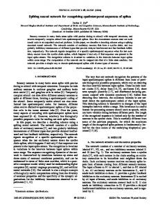
Fig. 2. The weight memories, implemented altogether as an array of block RAMs. Each column stores the weights for the synapses connecting each neuron of the network to the neuron instantiated by the column. An address in memory, received from the HSNN controller block, points to a single bit of a weight value from each column. During spike propagation, this address increments until it reaches the most significant bit of the last weights and is then reset. The Loading/unloading block on top of the memory is a serial to parallel register used during initialization and read back. TABLE I R ESOURCE USAGE FOR THE WHOLE SYSTEM
RESOURCE
USED
AVAILABLE
% USED
DEPENDENCE
FFs LUTs Slices BRAMs
14098 22815 8106 126
32640 32640 8160 132
43% 69% 99% 95%
P, N P, N N/A W, N2
composed of 4 segments, is used. The potential of a neuron is reset when it reaches the threshold. The length of a time step affects the neurons’ capacity to synchronize. A finer simulation is more time consuming, but leads to better synchronization. Consequently, an oscillation period is divided into 448 time steps. This exact number is chosen to allow some hardware optimizations of the piecewise linear function, minimizing the use of logic resources. V. R ESULTS Using 16 bits to code the membrane potential values and 11 bits for the weights, a fully connected network of up to 648 LIF neurons and 419904 synapses can be implemented on a single Xilinx XC5V50SXT device. The system is clocked at 100 MHz. A. Resource usage Table I summarizes the resources used by the whole system in terms of 6-input look-up tables (LUTs), flip-flops (FFs), slices and block RAMs (BRAMs). It also shows how these numbers relate to the number of neurons (N), and the width of weights (W) and potentials (P). Table II presents the resource usage for each functional block.
SCENARIO
CLOCK CYCLES
SPEED (AT 100 MHZ)
Best case Worst case
11k (P×N+M) 6,7M (P×N2 +M)
6M spikes/s 9,6k spikes/s
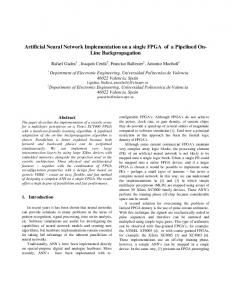
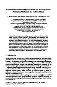
B. Performance Table III summarizes the processing power of the HSNN both in terms of the number of clock cycles required to compute one neuron oscillation period and the number of spikes processed per second. The performance depends on the number of simultaneously spiking neurons. In the best case scenario, all neurons fire at the same time step. On the other hand, if all neurons fire one at a time, the spikes per second count will be lower. Performance also depends on M, the number of time steps in an oscillation period. C. Image comparison task To illustrate the capability of the HSNN, we present the results of the comparison of a set of previously segmented images, according to the methodology in [2]. For this simple example, the features used are the pixel values of different regions of the images. Synaptic weights are then established as � � 1 wi,j = wmax 1 − , (2) 1 + e−α(|fi −fj |−δ) where wi,j is the weight connecting neuron i to neuron j, fi is the feature associated with neuron i and wmax , α and δ are tuning parameters which were respectively set to vthreshold /32, 100 and 4. The neurons’ membrane potentials are initialized randomly and the HSNN is run for a given number of oscillations, 85 periods in this case. The final potential values are plotted on Fig. 3 to give a general idea of the synchronized neurons. The result of the comparison is a score based on the correlation between the spike phases of the neurons of both images [2]. For the positive comparison task, the HSNN ran for 550 ms, not accounting for the loading time. Approximately 45k spikes were processed during the 85 oscillation periods. VI. D ISCUSSION The use of a square matrix to store the synaptic weights is burdensome, but it has two major advantages. First, it allows
Fig. 3. Illustration on an image comparison task: Original, segmented (input) and matched (output) images for the matching task. A. Original images. The two top images are different views of the same airplane. The third image is a different airplane. Images size are, from top to bottom, 90×26, 89×30 and 89×79 pixels; B. Segmented images used as input; C. Result of a positive matching. Most of the segments from the two images are synchronized (have the same color). Comparison score: 0.992; D. Result of a negative matching. Comparison score: 0.278.
the simulation of networks with any topology, making the HSNN very flexible in this regard. Also, the memory scheme is well suited for the implementation of plasticity, since there is a place allocated in the memory for every possible weight in the network. Plasticity rules are currently under evaluation and synaptic plasticity will be a part of future versions of the HSNN. The time required to process the 448 time steps of an oscillation period is proportional to the number of isolated spiking groups. During one oscillation period, every neuron will fire exactly once. If they are all synchronized, they will be processed during the same spike propagation step. A spike propagation step always takes the same exact amount of time to execute, no matter how many spikes occured in the time step. In a system that explicitly aims at producing synchrony, the processing speed rapidly improves as neuron groups form. For the image matching task, the network was initialized with random potential values. Thus, the HSNN started in one of the worst possible states, and got faster as synchronous neuron groups formed. The HSNN is constructed by duplicating and interconnecting slices. This repetitive design makes for easy placement on an ASIC. The routing is further simplified by the minimal amount of global signals. The slices mainly require local interconnection to neighboring units, hence the wire lengths are kept short. This data exchange scheme makes the system scalable, since wire lengths and the number of wire crossings will not increase with the amount of neurons. The current design uses up almost all of the resources on the FPGA. This complexifies the routing of the circuit, forbidding the use of a clock frequency higher than 100 MHz. The spike detection signal, a 648-input OR gate, is identified as the critical path of the design and is also a limiting factor. VII. F UTURE WORK The current implementation has been designed with focus on fully connected networks. As a result, it handles sparsely connected networks less efficiently. However, it is possible to slightly modify the system to store membrane potentials and synaptic weights in a shared memory with a variable boundary.
Different network topologies would result in different memory utilization ratios. Using time multiplexing, the system could efficiently handle small networks with dense connectivity and larger ones with sparse connectivity. This, however, would only be advantageous for regular network topologies, such as 8-neighbor connectivity. For non-regular connectivity, the scheme for fully connected networks would be used. ASICs would also be an interesting next step, as the bit slice architecture would be readily amenable to that technology. Furthermore, recent advances have been made in fabrication of memristors [10], a promising technology for the implementation of much denser versions of this system. VIII. C ONCLUSION The proposed system is a novel hardware neural network implementation adapted to oscillatory leaky integrate and fire models. The HSNN uses short interconnects, signal wires being used only between adjacent bit slices. Many other hardware spiking neural networks exist, but this implementation stands out by its practical versatility. Since computation is based on binding, a variety of signal processing tasks can be readily accomplished by the HSNN. The system is designed to take advantage of the synchrony in the network and processes groups of synchronous neurons very efficiently. The scalable architecture also offers the possibility to increase network size by using several interconnected FPGAs. Acknowledgments: This work has been funded by the Natural Sciences and Engineering Research Council of Canada (NSERC) and the Fonds qu´eb´ecois de la recherche sur la nature et les technologies (FQRNT). The images have been provided by MBDA during the ROBIN competition [11]. R EFERENCES [1] L. Maguire, T. McGinnity, B. Glackin, A. Ghani, A. Belatreche, and J. Harkin, “Challenges for large-scale implementations of spiking neural networks on fpgas,” Neurocomputing, vol. 71, no. 1-3, pp. 13–29, 2007. [2] R. Pichevar, J. Rouat, and L. T. Tai, “The oscillatory dynamic link matcher for spiking–neuron–based pattern recognition,” Neurocomputing, vol. 69, pp. 1837–1849, 2006. [3] R. Pichevar and J. Rouat, “Monophonic sound source separation with an unsupervised network of spiking neurones,” Neurocomputing, vol. 71, pp. 109–120, 2007. [4] P. Milner, “A model for visual shape recognition,” Psychological Review, vol. 81, pp. 521–535, 1974. [5] C. v. d. Malsburg, “The correlation theory of brain function,” MaxPlanck Institute for Biophysical Chemistry, Tech. Rep. Internal Report 81-2, 1981. [6] K. Cheung, S. R. Schultz, and P. H. Leong, “A parallel spiking neural network simulator,” 2009 International Conference on FieldProgrammable Technology., pp. 247–254, 2009. [7] B. Girau and C. Torres-Huitzil, “Massively distributed digital implementation of an integrate-and-fire LEGION network for visual scene segmentation,” Neurocomputing, vol. 70, no. 7-9, pp. 1186–1197, 2007. [8] D. Wang and D. Terman, “Image segmentation based on oscillatory correlation,” Neural Computation, vol. 9, no. 4, p. 805836, 1997. [9] J. Vega-Pineda, M. Chacon-Murguia, and R. Camarillo-Cisneros, “Synthesis of Pulsed-Coupled Neural Networks in FPGAs for RealTime Image Segmentation,” 2006 IEEE International Joint Conference on Neural Network Proceedings, pp. 4051–4055, 2006. [10] D. Strukov, G. Snider, D. Stewart, and R. Williams, “The missing memristor found,” Nature, vol. 453, no. 7191, pp. 80–83, 2008. [11] ROBIN inter. competitiion, http://robin.inrialpes.fr/.