A Pattern Matching Co-processor for Network Security Young H. Cho and William H. Mangione-Smith University of California, Los Angeles Department of Electrical Engineering Los Angeles, California
young,
[email protected]
ABSTRACT It has been estimated that computer network worms and virus caused the loss of over $55B in 2003. Network security system use techniques such as deep packet inspection to detect the harmful packets. While software intrusion detection system running on general purpose processors can be updated in response to new attacks. They lack the processing power to monitor gigabit networks. We present a high performance pattern matching co-processor architecture that can be used to monitor and identify a large number of intrusion signature. The design consists of a bank of pattern matchers that are used to implement a highly concurrent filter. The pattern matchers can be programmed to match multiple patterns of various lengths, and are able to leverage the existing databases of threat signatures. We have been able to program the filters to match all the payload patterns defined in the widely used Snort network intrusion detection system at a rate above 7 Gbps, with memory space left to accommodate threat signatures that become available in the future.
Categories and Subject Descriptors C.3 [Computer Systems Organization]: Special-purpose and application-based systems
General Terms Security,Design
Keywords Network security, Intrusion, Pattern matching, Pattern search, Snort
1. INTRODUCTION In August of 2003, the Internet worm named Sobig-F accounted for $29.7 billion of economic damages worldwide. This type of worm spreads through a file in the payloads of
Permission to make digital or hard copies of all or part of this work for personal or classroom use is granted without fee provided that copies are not made or distributed for profit or commercial advantage and that copies bear this notice and the full citation on the first page. To copy otherwise, to republish, to post on servers or to redistribute to lists, requires prior specific permission and/or a fee. DAC 2005, June 13–17, 2005, Anaheim, California, USA. Copyright 2005 ACM 1-59593-058-2/05/0006 ...$5.00.
e-mail. Most firewalls today are equipped to examine the packet headers only. Therefore, application layer network attacks can slip through the security systems undetected. While e-mail lends itself to store and scan techniques, such as those developed by anti-virus companies, other applications (e.g. databases) do not. An effective security measures for such attack is deep packet inspection [1]. Deep packet inspection not only examines the packet headers but also the payload data. Therefore, a security system that incorporates deep packet inspection offers better protection from attacks than traditional firewalls. It is evident that traditional firewalls that in much use today have not been effective in differentiating network packets containing the “Sobig-F” worm from normal e-mails. However, deep packet inspection system, such as Snort [2, 3, 4], can be configured to detect “Sobig-F” worm by searching for a specific 76 byte signature pattern in the payload.
1.1
Deep Packet Inspection
Since the network traffic is made of fragmented packets, each stream need to be reassembled before sending it to the deep packet inspection system. There are also some class of attacks that use unconventional protocol features to confuse and avoid the intrusion detection system. One such attack uses overlapping fragmented IP packets. Such must be eliminated by normalising the packets. Packet normalization produces consistantly clean network traffic without abnormalities [5]. Most of the currently available deep packet inspection systems use one or more general purpose processors running signature-based filtering software. Although these software systems can be easily reconfigured to detect new attacks, the underlying processor are not powerful enough to sustain acceptable filtering rate on gigabit (and above) networks. For example Snort, one of the most widely used software system, when configured with 500 real string patterns can only sustain a bandwidth less than 50 Mbps on a dual 1 Ghz Pentium 3 system. Since the payload data is under the control of the user application, all the patterns must be compared at every byte of the payload during the search process. Therefore, as the number of patterns in the software system increases, the filtering process needs more processing power. We refer to this pattern matching task as the dynamic inspection. This exhaustive search process on general purpose processor is expensive and the current software solutions are impractical for networks over 1 Gbps. Therefore, we have developed a specialized pattern matching co-processor for the dynamic pattern search.
In the following section, we briefly discuss how implementing pattern matching on reconfigurable hardware allows deep packet filtering on high bandwidth network. Then, in section 3, we present our new architecture for 1+ gigabit networks. We show that our system provides better performance while maintaining the flexibility of being reprogrammable. In section 4, we describe an initial pattern matcher implementation using the architecture. We develop algorithms to map all the patterns defined in the Snort rules into the design. We conclude with comparison of our implementation and other recent implementation of the pattern matcher.
2. RELATED WORK Sidhu and Prasanna mapped Non-deterministic Finite Automata (NFA) for regular expression into FPGA to perform fast pattern matching [6]. Subsequently, Franklin and Hutchings implemented a pattern search engine in JHDL, based on a subset of Snort IDS rules [7]. At around the same time, our FPGA filter used 8-bit decoders to build 3.2 Gbps pattern match engine on FPGA [2]. Sourdis mapped a similar design with a deeper pipeline to increase the filtering rate to 10 Gbps [8]. Our follow-up work and a similar JHDL based design by Clark and Baker made contribution in reducing the size of the design by eliminating duplicate logic [3, 9, 10]. Such improvement allowed the decoder design to fit into a single FPGA with performance of several gigabits per second Gokale et al. of Los Alamos National Laboratory implemented a fast re-programmable pattern search system using content addressable memories (CAM) [11]. Although such system does not require reconfiguration of FPGA, the low performance of CAM limits the usefulness as well as the number of mappable rules. Washington State University presented an approximate method using Bloom filters. They detect the patterns at 600 Mbps with number of false positives which is dependent on the number of rules as well as size of the alotted memory. Their approach uses hashing, and ultimately requires a secondary exact string comparison process to detect false positives [12]. Our latest FPGA implementation that uses a combination of 8-bit decoders and read-only-memory to reduce the amount of discrete gates by store partial information in the memory. The logic savings is achieved by using the decoders to generate the address for the partial pattern entry in a ROM. By balancing the use of the discrete gates and memory, this yields the highest performance per gate, thus far [3, 13]. Unlike the software solutions, many of the FPGA implementations satisfy the gigabit per second filtering rate. However, other than the CAM implementation [11] and the bloom filter design [12], the FPGA design compilation and reconfiguration time can be in the order of minutes to days. Such delay in reconfiguration may not acceptable as new worms are released to the network in higher frequency.
3. ARCHITECTURE A Snort rule contains information to search through all layers of network packets to detect a particular attack [4]. The most computationally intensive phase of the detection process is an exhaustive string search on the packet payload.
We present a compact and programmable pattern search coprocessor for multi-gigabit per second network.
3.1
Pattern Detection Module
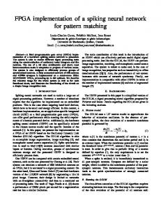
The basic pattern detection module (PDM) is shown in figure 1. The function of the pattern detection module is to efficiently detect segments of pattern using programmable hash functions followed by discrete string comparison. At every clock cycle the input pattern is hashed to generate an index. The index is then used as an address of a memory where the corresponding pattern is stored. The retrieved pattern from the memory is then compared with the input pattern to determine whether the pattern is an exact match. When there is a match, the index can be forwarded with an unique identifier for the pattern. Index
Hash
Detected Pattern Index Pattern
Memory
Offset Comp Input Pattern
Match Signal
Shifter Aligned Pattern
Figure 1: Pattern Detection Module We use parametrized and cascaded hardware so that the length of the patterns are not fixed. Therefore, the maximum length of the input bytes that is used to generate the hashed index is the minimum length of the patterns detectable by a single PDM. Moreover, the maximum range of the hashed index determines the maximum entries that can be stored in the memory. For instance, if two byes of the input pattern are hashed to generate the index, the PDM can be configured to detect maximum of 65,536 patterns with the minimum length of two bytes.
3.1.1
Hashed Index
Hashing the substrings in a static position places a constraint on which patterns can be detected by one PDM. If the first two bytes of all the patterns are used for generating the index, some would have the same hash value and could not be stored in the same PDM. For higher resource utilization, we allow the index to be generated by any substring of the pattern. In practice, each pattern consists of more than one unique substring. By allowing the hash function to start at different byte offsets of the pattern, the PDM memory utilization can be improved. Therefore, the byte offset data is stored with the pattern information in the memory. Using the offset and the pattern length, the input pattern is shifted and compared against the target pattern as shown in figure 1. Since the index is generated from a substring of the pattern at a different offset, the timing of the identification index output may not indicate the starting byte of the pattern. By using the offset value with the switched pipeline as the one shown in figure 2, the index output timing can be adjusted to correspond with the start of the pattern.
3.1.2
Prioritized Parallel Modules
Some patterns, especially the ones with a small set of unique substrings, cannot be mapped on to the same PDM module because the entries for their hashed indices might
Index
0
1
1
1
0
0
0
n
Offset
n−1
1 0 0
1
Decoder
Every long pattern can be broken into several short pattern segments. If we match the order and the timing of the segment sequence, we can effectively detect the corresponding long pattern. As in figure 3, the long pattern is divided into smaller segments that fit in to a specific PDM. These segments are stored in the PDMs along with a flag bit that indicates that it is a segment of a long pattern. The detected indices are forwarded to the long pattern state machine (LPSM).
Figure 2: Switched Pipeline
3.2.2 be used by another pattern (e.g. pattern that is made of all zeros). Therefore, more than one PDM must run in parallel to detect multiple patterns with equal hashed values. In order to increase memory utilization, each PDM can have different sized memory and logic based on a range of target patterns. To maintain consistent output timing for the parallel modules, smaller PDMs may need extra stages of pipeline to match with longest PDM. If the PDMs are configured to examine the same data simultaneously, in most cases, only one PDM will output a valid index for a pattern match. By extending the output bits to indicate its module number, the outputs from the parallel PDMs can be merged to produce one index output. Depending on the memory content of the PDMs, more than one PDM can output valid indices at a given cycle. Multiple detections occur if one pattern is a substring, starting with the first byte, of another pattern. We refer to such patterns as “overlapping patterns.” When more than one index is detected in the same cycle, it is sufficient to output the index for the longest pattern since it also indicates the detection of the shorter patterns. Our design use chains of multiplexors to assign the priorities and merge the outputs of parallel PDMs. The longer of any conflicting patterns must be stored in the PDM with the highest priority. The above PDM architecture allows the detection of patterns of lengths that are less than or equal to that of the widest memory module from all the PDMs. We refer to such pattern as “short pattern.”
3.2 Long Pattern State Machine For applications such as Snort, where some patterns are long, it is not efficient to have the PDM with memory wide enough to store those patterns. In this section, we describe another component that uses PDMs to detect patterns that are longer than the width of PDM memories.
3.2.1
Sequence of Segments Index A
Index B
Index C
Index D
THE PATTERN THAT IS TOO LONG TO FIT IN A PDM
Input Stream
PDM 0
PDM 1
PDM 2
Parallel PDMs
Priority Multiplexor Index
Figure 3: Divided segments of the long pattern maybe detected by different PDMs
Programmable State Machine
The LPSM examines the sequence of segment indices for the correct ordering and the timing to detect the corresponding long pattern. As shown in figure 4, the LPSM is consists of the memory and the pipeline similar to that of PDM. Unlike the PDM, the memory only contains information for the current and the next “state”. Each state is expressed as number which is based on the index of the pattern segments detected by the PDMs. Segment Index reset Memory
comp
next state
type
delay
Switched Pipeline next valid LPSM bits
AND
Register current state
predicted comp state match To other LPSMs
Figure 4: Long Pattern State Machine The memory entry in LPSM with the state information is loaded using part of the index identified by the PDMs. The rest of the bits for the index are stored in the memory to verify the current state. The entry also has a type field that indicates whether the current index is the first, the middle, or the last segment of the long pattern. The entry also specifies what the next state is and when it is expected to be detected by the PDMs. The sequence matching process is only initiated when the type of the current state indicates that it is the start of a long pattern segment. The expected next state is forwarded to the switched pipeline like the one used in PDM to add the appropriate delay. When the next index reaches the end of the pipeline, it is compared with the actual current state to determine whether there was a match. When the previous next state is an exact match of the current state at the end of the pipeline, the expected next state is forwarded in to the pipeline as before. If the expected next state does not match the current state, this process is terminated without any output. Otherwise, the process continues until the current state is specified as the last segment of the long pattern. Then the last matching index is forwarded as an index for the detected long pattern.
3.2.3
Parallel LPSM
Depending on the depth of the LPSM memory and the long pattern indices, more than one entry maybe necessary for the same address. In order to address this, more than one LPSM can run in parallel to detect more than one sequence of states. In order to interoperate between the LPSMs, the match bit is forwarded to the modules that contain all the corresponding next state for the current state. When any of the LPSM receives the match bit, its expected next state is forwarded to the pipeline regardless of the result in its own comparator.
3.3 System Integration and Features Unlike the FPGA designs, which required functional circuit changes, this design only requires updating memory values. With the correct memory values, the short patterns are identified using the PDMs whereas the long patterns are identified using both the PDM and the LPSM modules.
3.3.1
Reusing Memory Entries
Since the multiple index sequences can be tracked by the parallel LPSMs, they can be programmed to reuse pattern segments that appear in more than one pattern. By reusing the pattern segments for more than one pattern, the memory requirement for PDM can be reduced. Aho and Corasick’s keyword tree [14] is used in many efficient software pattern search algorithms, including the Snort IDS [4]. This algorithm is used in the FPGA implementation to reduce the hardware area [3]. We also apply the algorithm to configure the PDM memories. A keyword tree is a way to store a set of patterns into an optimized tree of common keywords. The conversion not only reduces the amount of required storage, but also narrows the number of potential patterns as the pattern search algorithm traverses the tree. First, the pattern set must be analyzed to form the keyword trees. Once the keyword trees are generated, its keywords are stored as pattern segments in the PDMs and the edges are stored as the state transitions in the parallel LPSMs. This optimization allows the duplicate pattern segments to be collapsed into a single segment to save PDM memory space.
4. SNORT IMPLEMENTATION Snort is one of the most widely used network intrusion detection system (NIDS) that uses deep packet inspection. It is open source software that can be configured with the set of signatures that are used to identify network attacks. In June 2004, the Snort rule set contained 1,729 string patterns that should to be searched dynamically in the network payload. To evaluate the effectiveness of our architecture, we implement the filter based on the architecture to support the entire Snort rule set. Our design contains additional memory space for flexible configuration in the face of new attacks.
4.1 Hardware Configuration The dimension of the memories, the number of PDMs, the number of LPSMs, and the hash functions are the architecture parameters. These parameters allow the designer to customize the filter for a given threat profile. Depending on the pattern set, the parameters of the architecture may differ dramatically to optimize the resource utilization. For
example, the designer may decide that LPSMs are unnecessary if all the target patterns are short and uniform in length. On the other hand, the designer may choose to have small PDM followed by many parallel LPSMs if the patterns consists of repetitive set of common substrings. Determining the parameters of the architecture is a complex process which effects the behavior of the system. However, this process is beyond the scope of this paper. Therefore, we attempt to describe one system we have implemented to successfully map the entire Snort rules.
4.1.1
PDM Parameters
The length of the patterns range from 1 to 122 bytes in Snort rule set. The contents of the patterns vary from binary sequences to ASCII strings. Therefore, we design the filter to support patterns of various lengths as well as the content. For the pattern set, using different size memories in the PDMs can increase the memory utilization and decrease the logic area. However, we choose to set the dimension of all the PDM to be same to simplify of the design process. The dimension of the memory in each PDM is 146 bits by 512 entries. The memory is wide enough to store all the information necessary to detect up to 17 bytes long pattern. In our filter, eight of these PDM units are connected in parallel to provide 8-levels of priority. The filter takes two consecutive input bytes to generate the 9 bit address for the PDM memories. As we mentioned in the architecture description, the minimum pattern length for our filter, therefore, is 2 bytes long. Since single byte pattern can be more efficiently detected using byte decoders, we do not map them on the filter. The hash function logic consists of series of multiplexors to independently choose any 9 bits of the 16 bits. The hash logic in each PDM are individually configurable to give more flexibility for the programmer.
4.1.2
LPSM Parameters
The design consists of eight units of LPSMs, each with 29 bit by 512 memory entries. Although we found that 256 memory entries per LPSM is sufficient to completely map the entire Snort contents, we use the bigger memory for easier filter programming in the future. Since each LPSM can match different sequence of pattern, the design is capable of reusing one short pattern segment up to eight times. In order to save memory space, the hashing logic for LPSM uses portion of index bits to load the state information. The index bits 11 through 2 are directly connected to the address of the memory while the rest of the bits are, later, matched with the memory content.
4.2
Pattern Software
Once the hardware parameters are set, the resulting datapath can be programmed using several different algorithms. Depending on the complexity of the algorithms and the patterns, there can be a big difference in compilation time as well as the program size. In general, reducing the size of the program takes longer compilation time. However, smaller program tend to yield cleaner indexing result. The system performance stays constant, regardless the size of the program. Due to variety of possible algorithms and optimizations that can be applied to program the filter, we believe this step is also beyond the scope of this paper. Therefore, we
present a few direct and effective algorithms used to map the entire pattern set defined in the Snort rules.
4.2.1
Pattern Preprocessing
For the above hardware, the long patterns must be broken into shorter segments of 17 bytes or less. Due to the priorities assigned to the PDM units, the short patterns do not have to be unique. However, eliminating duplicate patterns would save memory space. In order to identify each pattern with an unique index, the last segment of every pattern must be different. A simple algorithm is used to break the long patterns into smaller segments that fit in the PDMs. The algorithm produces a list of segments containing overlapping patterns. The overlapping patterns can assert detections in several PDMs in a single cycle. By assigning higher priority to the longer of any two overlapping patterns, the detection of the longer index also indicates the detection of shorter patterns. There is no need for priority for the non-overlapping patterns. If any segment of the long pattern is an overlapping pattern, it must have the highest priority. Such priority is automatically assigned when the algorithm divides the pattern into maximum lengthed segments. Once the list of pattern segments are generated, it can be used to generate index sequences for all the long patterns. When the long patterns are divided into smaller segments, the corresponding sequence of segment identifiers are recorded along with the time delay between subsequent segments and the type flags. These data are programmed into LPSM to keep track of the long patterns.
4.2.2
Programming the Filter
All the PDMs and the LPSMs are memory mapped. As far as the programmer is concerned, the filter can look like a large memory. The parameters of the hash functions can be also treated as a memory mapped location. Our implementation uses two ports to program the filter, one for the memory modules in the PDMs and LPSMs and the other for programming hash functions. Before the filter is programmed, the data for the pattern matching modules must be mapped on to a virtual filter with same configuration. The mapping procedure is necessary to determine exact address locations for all data. Once the data is correctly mapped in to the virtual memory space, programming the filter is equivalent to writing into a memory. The list of pattern segments, their length, and the control information from the preprocessing step are mapped on to the PDMs. Our mapper uses an algorithm that incrementally fills the PDM memory according to the pattern segment priority and the hash value. If the hash function fails to map the patterns, it simply changes the hashing parameters to re-map the patterns. These simple algorithm mapped the entire Snort on to our initial implementation. However, the segments were not evenly distributed into all the memory modules. A better algorithm can use the distribution of the patterns in the memory and the frequency of possible indices for each pattern to efficiently map the pattern. Such mapping analysis will take longer execution time. The sequences of indices and other control fields are mapped on to the LPSMs. Each index is mapped on to one LPSM
pointing to one or more LPSMs that matches the corresponding next index. If there are patterns with same beginning indices, the programmer can choose to use only one LPSM to keep track of all the patterns until it branches off to different patterns. This optimization will allow the unused entries of the LPSMs to be used for other sequence of patterns. After the data is successfully mapped on to the virtual filter, the memory values can be directly copied in to the filter memories.
4.3
Results
The hardware design is written in structural verilog and the programmer is written in C++. As described in the previous sections, the hardware is composed of 8 parallel units of PDMs and 8 parallel units of LPSMs. As of June 2004, there are total of 1,729 unique patterns with lengths 2 to 122 bytes in Snort NIDS. The total number of bytes that the filter need to compare are 22,340 bytes. Using the simple algorithms, the programmer successfully configured the hardware to filter the entire set of patterns. The pattern mapping would be more efficient if the memory usage distribution and the index information of patterns are used. Although our algorithm does not consider them in during the mapping process, the hardware still proved to be robust enough to store the rule set. During the programming process, 374 long patterns are transformed into 752 short pattern segments; making the total number of patterns for the PDMs 2,107. Along with the segments, the LPSMs are programmed to make up to 7 state transitions. The entire pattern set occupies approximately 50% of the PDM and 18% of LPSM memory, leaving enough space many additional patterns. In fact, given a complex algorithm that reuses duplicate substring, the filter can have more than double the number of patterns defined in the Snort NIDS. On an AMD Athlon XP 1800+ processor under cygwin, the total runtime of the programmer to process and map the patterns into the virtual memory space is 771 msec. We generated the memory modules in Verilog with the contents of the virtual memory to verify our design in simulation environments. Module PDM Logic LPSM Logic PDM Mem LPSM Mem DPF Filter
Area 0.075 mm2 0.024 mm2 0.844 mm2 0.168 mm2 -
Units×Area 0.600 mm2 0.188 mm2 6.752 mm2 1.342 mm2 8.882 mm2
Cr-path


![Graph Pattern Matching Revised for Social Network ... [PDF]](https://m.moam.info/img/260x300/graph-pattern-matching-revised-for-social-network-_648635a3098a9ebb128b457c.jpg)

