Hindawi Publishing Corporation Mathematical Problems in Engineering Volume 2016, Article ID 7632176, 17 pages http://dx.doi.org/10.1155/2016/7632176
Research Article A Meshless Radial Basis Function Based on Partition of Unity Method for Piezoelectric Structures Sen Li,1 Linquan Yao,2 Shichao Yi,3 and Wei Wang2 1
School of Mathematical Sciences, Soochow University, Suzhou 215006, China School of Urban Rail Transportation, Soochow University, Suzhou 215006, China 3 School of Mathematics and Physics, Jiangsu University of Science and Technology, Zhenjiang 212003, China 2
Correspondence should be addressed to Linquan Yao;
[email protected] Received 27 August 2016; Accepted 20 October 2016 Academic Editor: Lihua Wang Copyright © 2016 Sen Li et al. This is an open access article distributed under the Creative Commons Attribution License, which permits unrestricted use, distribution, and reproduction in any medium, provided the original work is properly cited. A meshless radial basis function based on partition of unity method (RBF-PUM) is proposed to analyse static problems of piezoelectric structures. The methods of radial basis functions (RBFs) possess some merits: the shape functions have high order continuity; ℎ-adaptivity is simpler than mesh-based methods; the shape functions are easily implemented in high dimensional space. The partition of unity method (PUM) easily constructs local approximation. The character of local approximate space can be varied and regarded as 𝑝-adaptivity. Considering the good properties of the two methods, the RBFs are used for local approximation and the local supported weight functions are used in the partition of unity method. The system equations of the RBF-PUM are derived using the variational principle. The field variables are approximated using the RBF-PUM shape functions which inherit all the advantages of the RBF shape functions such as the delta function property. The boundary conditions can be implemented easily. Numerical examples of piezoelectric structures are investigated to illustrate the efficiency of the proposed method and the obtained results are compared with analytical solutions and available numerical solutions. The behaviors of some parameters that probably influenced numerical results are also studied in detail.
1. Introduction Piezoelectric material is a new advanced material which can be used for developing smart structures with self-controlling and self-monitoring capabilities. The essential feature of piezoelectric material is the capability of energy transformation between electrical energy and mechanical energy. Hence, piezoelectric materials have been widely used as intelligent control devices such as sensors, actuators, ultrasonic transducers, and active damping devices. Due to the complicated properties of piezoelectric materials, various approaches including analytical and numerical methods have been proposed to deal with the problems involving piezoelectric materials. However, the analytical solutions are rather restricted in general and difficult to find unless some geometry and boundary are relatively simple. Accurate, efficient, and robust numerical methods are required to simulate piezoelectric problems. Some numerical methods have been proposed to analyse piezoelectric
problems such as the finite element method (FEM) [1–4], the boundary element method (BEM) [5–7], and the smoothed FEM [8]. Among them, the FEM is considered to be an effective method for mechanical and electromechanical coupling problems. Since the FEM is a mesh-based method, the FEM may lead to large errors when mesh distortion appears or low quality meshes are adopted. Mesh distortion may occur in the problems of large deformation, crack propagation, and so forth. An alternative method is called meshless method which can eliminate mesh-based problems. In the meshless method, only a set of scattered nodes is required to represent problem domain and boundary and therefore the adaptivity is simpler than mesh-based methods. The initial ideal of meshless method dates back to the smooth particle hydrodynamics (SPH) method proposed by Lucy [9] and Gingold and Monaghan [10] for modeling astrophysical phenomena. Then several meshless methods including the diffuse element method (DEM) [11], the element-free Galerkin (EFG) method [12], the reproducing
2 kernel particle method (RKPM) [13], the ℎ-𝑝 clouds method [14], the point interpolation method (PIM) [15–17], the radial basis function point interpolation method (RPIM) [18, 19], the moving Kriging (MK) meshless method [20], and the meshless local Petrov-Galerkin (MLPG) method [21–25] have been proposed to solve partial differential equations and mechanical problems. Most of these methods are carried out based on weak form equations and a set of background cells or local subdomains is required to implement numerical integration. In the MLPG method, the moving least square (MLS) approach [26] is used to construct approximate functions and the major drawback is that the MLS shape functions lack interpolation property. The boundary conditions cannot be imposed directly and some methods should be proposed to overcome this problem, such as the Lagrange multiplier method [12] and the penalty function method [18]. In the RPIM, radial basis functions (RBFs) are used to construct the shape functions. The variable is only related to the distance between interpolation point and node and therefore the method is easily implemented in high dimension space. The behaviors of radial basis functions [27–32] have been widely investigated. Radial basis functions are also used in the meshless collocation method [33–35] which is based on the strong form equations. These methods based on the RBFs have obtained high accurate solutions and have been shown excellent interpolation property. Some methods coupling with the partition of unity method (PUM) [36, 37] have also been investigated in mechanical problems in recent years. The main advantages of the PUM are the flexibility in choosing the local approximation which can be used the approaches of the MLS, the PIM, and the RPIM. Rajendran and Zhang [38] developed a new “FE-Meshfree” method using the concepts of partition of unity method. In this method, the FEM shape functions are used for weight functions and the meshless approach is used to construct local approximation. Some of important works including Q4-LSPIM [38, 39], Q4-RPIM [40], and T3-RPIM [41] have been presented for static and vibration analysis of mechanical problems and obtained very accurate results. In this paper, a meshless radial basis function based on partition of unity method (RBF-PUM) is proposed to analyse 2D piezoelectric structures. The RBFs are used for local approximation and Shepard’s method [44] is used for the construction of weight functions in the partition of unity method. The RBF-PUM method has been studied by Wendland [45] and Fasshauer [29] and successfully applied in the convection diffusion equations [46] using the collocation method. The field variables are approximated using the RBFPUM shape functions which inherits all good advantages of the PUM and RBFs. The performance of the RBF-PUM shape functions will be discussed in detail. The rest of this paper is organized as follows. The formulation of the RBF-PUM method is presented in Section 2. The governing equations and variational equations for 2D piezoelectric problems are given in Section 3. Numerical examples are considered to verify the effectiveness of the proposed method in Section 4. Finally, we end this paper with some conclusions in Section 5.
Mathematical Problems in Engineering
2. The Formulation of the RBF-PUM Method 2.1. The Partition of Unity Method. This section recalls briefly the partition of unity method for 2D problem. Let Ω ⊂ R2 be a problem domain and {Ω𝑖 }𝑀 𝑖=1 be an open cover of Ω satisfying some mild overlapping conditions such that ∀x ∈ Ω
𝐼 (x) = {𝑖 | x ∈ Ω𝑖 } , 1 ≤ card (𝐼 (x)) ≤ 𝑀,
(1)
where 𝐼(x) is an index set of the patches in which the interpolation point x locates and 𝑀 is the total number of all patches. For every patch Ω𝑖 , we construct a local approximation 𝑢𝑖 (x). According to the concept of the partition of unity method, the global approximation function 𝑢ℎ (x) can be expressed as 𝑀
𝑢ℎ (x) = ∑𝑤𝑖 (x) 𝑢𝑖 (x) ,
(2)
𝑖=1
where {𝑤𝑖 (x)}𝑀 𝑖=1 are weight functions. The weight functions are compactly supported, nonnegative, and continuous and satisfy the partition of unity: supp (𝑤𝑖 (x)) = Ω𝑖
𝑖 = 1, . . . , 𝑀,
𝑀
(3)
∑𝑤𝑖 (x) = 1 on Ω. 𝑖=1
Equation (3) shows that 𝑤𝑖 (x) = 0 for 𝑖 ∉ 𝐼(x). Therefore, (2) can be rewritten as 𝑢ℎ (x) = ∑ 𝑤𝑖 (x) 𝑢𝑖 (x) . 𝑖∈𝐼(𝑥)
(4)
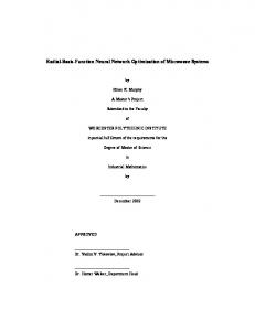
2.2. Construction of Weight Functions with Partition of Unity Property. For the partition of unity method, the patch can be of any shape, such as square, circular, spherical, or hyperspherical. The basic requirement for all patch domains is that they cover problem domain and boundary. In this paper, the circular patch is used for the analysis in the PUM. 𝑀 Let {𝑋𝑖 }𝑀 𝑖=1 be a set of central points of patches {Ω𝑖 }𝑖=1 𝑀 and {𝑟𝑖 }𝑖=1 be the radiuses as shown in Figure 1. Nonnegative and compactly supported weight functions {𝑤𝑖 }𝑀 𝑖=1 can be constructed using Shepard’s method [44] as follows: 𝑤𝑖 (x) =
𝜑𝑖 (x)
∑𝑀 𝑘=1 𝜑𝑘 (x)
, 𝑖 = 1, . . . , 𝑀,
where function 𝜑𝑖 (x) is given by x − 𝑋𝑖 ). 𝜑𝑖 (x) = 𝜑 ( 𝑟𝑖
(5)
(6)
In the present study, Wendland function [47] is used for function 𝜑(𝑟): 4 {(1 − 𝑟) (1 + 4𝑟) 𝜑 (𝑟) = { 0 {
in which
x − 𝑋𝑖 𝑟= . 𝑟𝑖
0 ≤ 𝑟 ≤ 1, 𝑟 > 1,
(7)
(8)
Mathematical Problems in Engineering
3 where
Ω2
Ω1
4
1 r1 2 3
r2
7
a𝑇 = [𝑎1 , 𝑎2 , . . . , 𝑎𝑛𝑖 ] ,
10
b𝑇 = [𝑏1 , 𝑏2 , . . . , 𝑏𝑚 ] ,
× 5
8
11
6
9
12
u𝑇𝑖 = [𝑢1 , 𝑢2 , . . . , 𝑢𝑛𝑖 ] , R0 𝑅1 (𝑥1 , 𝑦1 ) 𝑅2 (𝑥1 , 𝑦1 ) [ [ 𝑅1 (𝑥2 , 𝑦2 ) 𝑅2 (𝑥2 , 𝑦2 ) [ =[ .. .. [ [ . . [ [𝑅1 (𝑥𝑛𝑖 , 𝑦𝑛𝑖 ) 𝑅2 (𝑥𝑛𝑖 , 𝑦𝑛𝑖 )
Figure 1: Definition of interpolation point 𝑥, central point (red ∗), patch (red circle), and support radius (or patch size). The patches for interpolating point 𝑥 are defined as Ω1 = {1, 2, 4, 5, 6, 8} and Ω2 = {7, 8, 9, 10, 11, 12}. The support domain of interpolation point 𝑥 is ̂ = Ω1 ∪ Ω2 = {1, 2, 4, 5, 6, 7, 8, 9, 10, 11, 12}. defined as Ω
2.3. Radial Basis Function Method. In the present method, radial basis functions with polynomial terms are used to construct the local approximation of the partition of unity method. Using radial basis functions with polynomial functions, the local approximation 𝑢𝑖 (x) is given by 𝑛𝑖
𝑚
𝑖=1
𝑗=1
𝑢𝑖 (𝑥, 𝑦) = ∑𝑅𝑖 (𝑥, 𝑦) 𝑎𝑖 + ∑𝑝𝑗 (𝑥, 𝑦) 𝑏𝑗
,
(10)
where 𝑑𝑖 = √(𝑥 − 𝑥𝑖 )2 + (𝑦 − 𝑦𝑖 )2 and 𝜂 and 𝑞 are two shape parameters. Enforcing (9) to pass through all node values in patch Ω𝑖 , the following equations are obtained: u𝑖 = R0 a + P𝑚 b,
⋅ ⋅ ⋅ 𝑅𝑛𝑖 (𝑥𝑛𝑖 , 𝑦𝑛𝑖 )]
⋅⋅⋅
1
⋅⋅⋅
𝑥𝑛𝑖
] ] ] ] ⋅⋅⋅ 𝑦𝑛𝑖 ] ]. ] .. ] ] d . ] ⋅ ⋅ ⋅ 𝑝𝑚 (x𝑛𝑖 )]
Adding polynomial terms is an extra requirement. In order to guarantee unique approximation [48], the following conditions are usually imposed: 𝑛𝑖
∑𝑝𝑗 (𝑥𝑖 , 𝑦𝑖 ) 𝑎𝑖 = 0, 𝑗 = 1, 2, . . . , 𝑚,
(13)
𝑖=1
(9)
where R(𝑥, 𝑦) and p(𝑥, 𝑦) represent radial basis and polynomial functions, respectively. 𝑛𝑖 is the total number of nodes in patch Ω𝑖 and 𝑚 represents the number of polynomial terms. a and b are unknown vectors to be determined. In the radial basis function 𝑅𝑖 (𝑥, 𝑦), the variable is only related to the space distance between interpolation point x and node x𝑖 and therefore the RBF method is easily implemented in high dimensional problems. Some radial basis functions such as multiquadric radial basis function (MQRBF), thin plate spline radial basis function (TPS-RBF), and Gaussian radial basis function (EXP-RBF) have been widely investigated in [18, 27–32]. For the present method, the MQRBF is adopted and given by 𝑅𝑖 (𝑥, 𝑦) = (1 +
] ⋅ ⋅ ⋅ 𝑅𝑛𝑖 (𝑥2 , 𝑦2 ) ] ] ], .. ] (12) ] d . ]
which can be rewritten in matrix form
= R (𝑥, 𝑦) a + p (𝑥, 𝑦) b,
𝑞 𝜂2 𝑑𝑖2 )
1 1 [ [ 𝑥1 𝑥2 [ [ [ 𝑦1 𝑦2 P𝑇𝑚 = [ [ . .. [ . [ . . [ [𝑝𝑚 (x1 ) 𝑝𝑚 (x2 )
⋅ ⋅ ⋅ 𝑅𝑛𝑖 (𝑥1 , 𝑦1 )
(11)
P𝑇𝑚 a = 0.
(14)
Vectors a and b can be obtained by (11) and (14), and then substitute into (9), the local approximation function 𝑢𝑖 (𝑥, 𝑦) is eventually expressed as 𝑢𝑖 (𝑥, 𝑦) = Φ𝑖 u𝑖 ,
(15)
where Φ𝑖 = R (𝑥, 𝑦) S𝑎 + P (𝑥, 𝑦) S𝑏 , −1
S𝑏 = [P𝑇𝑚 R0 P𝑚 ] P𝑇𝑚 R0−1 ,
(16)
S𝑎 = R0−1 [I − P𝑚 S𝑏 ] . The existence of inverse matrix R0−1 for arbitrary scattered nodes has been given by Wendland [30]. Finally, the shape functions associated to all nodes in the patch Ω𝑖 can be expressed as 𝑛
Φ𝑖 (x) = [𝜙𝑖1 (x) , 𝜙𝑖2 (x) , . . . , 𝜙𝑖 𝑖 (x)] .
(17)
2.4. RBF-PUM Shape Functions and Mathematical Properties. The radial basis functions are selected as local approximation
4
Mathematical Problems in Engineering
and the global approximation 𝑢ℎ (x) in (4) can be expressed as ̃𝑠 , ̃ (x) U 𝑢ℎ (x) = ∑ 𝑤𝑖 (x) Φ𝑖 (x) u𝑖 = Φ (18)
1.5
𝜙
−0.5
(20)
where 𝛼, 𝛽 ∈ N20 are multi-indices and D𝛼 = 𝜕|𝛼| /𝜕𝑥𝛼 is a spatial differential operator. The RBF-PUM method inherits the advantages of the RBF meshless method and the following are the mathematical properties of the RBF-PUM shape functions: (1) The RBF-PUM shape functions possess the delta function property:
0
0.6
0.8
1
0.6
0.8
1
0 −10 −20
0
0.2
0.4 x
Figure 2: RBF-PUM shape functions and their derivatives in 1D space.
3. Variational Equations for Piezoelectric Structures The variational equations for linear piezoelectricity are presented in this section. Considering a two-dimensional piezoelectric problem in domain Ω with boundary Γ, the governing equations are given by ∇𝑠𝑇𝜎 + f = 0, ∇𝑇 D = 0,
(21)
(2) The RBF-PUM shape functions possess the property of partition of unity: ̂ 𝑛
(22)
𝑖=1
(3) If the RBFs include at least linear polynomial terms, the RBF-PUM shape functions can ensure an exact reproduction of linear polynomials; that is, (23)
𝑖=1
(4) Local compactly supported property. (5) Especially for card(𝐼(x)) = 1, the RBF-PUM shape functions are the RBF shape functions as well as their derivative functions. The RBF-PUM shape functions and their derivative functions are shown in Figures 2 and 3 for 1D and 2D space, respectively. In Figure 2, six regularly distributed nodes in interval [0, 1] are used for the construction of the shape functions and plotted in different colours. In Figure 3, the shape function and its derivative of point (0, 0) are plotted in interval [−1, 1] × [−1, 1]. It can be observed that the RBFPUM shape functions have interpolation property and local compactly supported property.
(24)
where 𝜎, D are stress and electric displacement vector, respectively. f is body force density. The operators ∇𝑠 and ∇ in 𝑥-𝑧 plane are given by 𝜕 𝜕 𝑇 0 [ 𝜕𝑥 𝜕𝑧 ] ] , ∇𝑠 = [ [ 𝜕 𝜕] 0 [ 𝜕𝑧 𝜕𝑥 ] ∇ =[
̂ 𝑛
̃ (x) 𝑥𝑖 = 𝑥. ∑𝜙 𝑖
6
10 d𝜙/dx
(19)
̂ It is where 𝑛̂ is the total number of nodes in domain Ω. noted that the dimension of the RBF shape functions Φ𝑖 (x) may be less than 𝑛̂, but they can be expanded to vector with dimension 𝑛̂. The derivative functions of the RBF-PUM shape functions can be obtained using Leibniz’s rule:
̃ (x) = 1. ∑𝜙 𝑖
0.4
5
20
̃ (x) , . . . , 𝜙 ̃ (x)] , ̃ (x) , 𝜙 = [𝜙 ̂ 1 2 𝑛
̃ (x𝑗 ) = 𝛿𝑖𝑗 . 𝜙 𝑖
0.2
4
x
̃ (x) = ∑ 𝑤𝑖 (x) Φ𝑖 (x) Φ
𝛼 ∑ ( ) D𝛽 𝑤𝑖 (x) D𝛼−𝛽 Φ𝑖 (x) , 𝑖∈𝐼(x) |𝛽|≤|𝛼| 𝛽
3
0
̃ 𝑠 is nodal displacement vector composed of all the where U ̃ is ̂ = ⋃𝑖∈𝐼(x) Ω𝑖 and Φ(x) nodes in the union of the patches Ω the vector of the RBF-PUM shape functions given by
̃ (x) = ∑ D𝛼 Φ
2
0.5
𝑖∈𝐼(x)
𝑖∈𝐼(x)
1
1
(25)
𝜕 𝜕 𝑇 ] . 𝜕𝑥 𝜕𝑧
The boundary conditions are given by 𝜎n = t, on Γ𝜎 u = u, on Γ𝑢 Dn = −𝑞, on Γ𝑞
(26)
𝜙 = 𝜙, on Γ𝜙 , where u and 𝜙 denote prescribed displacements and electric potential, respectively. n is the unit outward normal vector. t and 𝑞 are the surface traction and charge, respectively. The strain vector related to displacement is ̂ = B𝑢 u ̂ 𝜀 = ∇𝑠 u = ∇𝑠 N𝑢 u
(27)
Mathematical Problems in Engineering
5
RBF-PUM shape functions at (0, 0)
RBF-PUM shape functions derivatives 𝜕𝜙/𝜕x at (0, 0)
8 1.5
6
1
4 𝜕𝜙/𝜕x
2 𝜙 0.5 0
0 −2 −4
−0.5 1 1
0.5 0 y
0.5
0
−0.5 −1
−1
−0.5
−6 −8 1
0.5
x
0 y
−0.5
−1
−1
−0.5
0.5
0
1
x
Figure 3: RBF-PUM shape function and its derivative of point (0, 0) in 2D space.
and the electric field vector is
The constitutive relations can also be expressed explicitly in matrix form:
̂ = −B𝜙 𝜙, ̂ E = −∇𝜙 = −∇ (N𝜙 𝜙)
(28)
where ̂ = [𝑢1 𝑤1 𝑢2 𝑤2 ⋅ ⋅ ⋅ 𝑢𝑛̂ 𝑤𝑛̂ ] u
𝑇
̃ 0 ⋅⋅⋅ 𝜙 ̃ 0 𝜙 ̂ 1 𝑛 N𝑢 = [ ] ̃ ⋅⋅⋅ 0 𝜙 ̃ 0 𝜙 ̂ 1 𝑛 (29)
0 0 ] [ [ ̃ ̃ ] B𝑢 = [ 0 𝜙 ⋅⋅⋅ 0 𝜙 ] ̂ 1,𝑧 𝑛 ,𝑧 ] [ ̃ ̃ ̃ ̃ 𝜙 𝜙 𝜙 ⋅ ⋅ ⋅ 𝜙 ̂,𝑧 ̂,𝑥 ] 𝑛 𝑛 [ 1,𝑧 1,𝑥 ̃ 𝜙 1,𝑥 ⋅ ⋅ ⋅ B𝜙 = [ ̃ [𝜙1,𝑧 ⋅ ⋅ ⋅
𝑠11 𝑠13 0 𝜎𝑥 0 𝜀𝑥 ] [ ] [ [ 𝜀 ] [𝑠 𝑠 [ 𝑧 ] = [ 13 33 0 ] [ 𝜎𝑧 ] − [ 0 [0
0 𝑠55 ] [𝜏𝑥𝑧 ]
[𝑑15
𝑑31
𝐸𝑥 𝑑33 ] ][ ], 𝐸𝑧 0 ]
𝜎𝑥
(32)
0 0 𝑑15 [ ] 𝐸𝑥 𝐷𝑥 𝜉11 0 ] [ 𝜎𝑧 ] + [ ][ ], [ ]=[ 0 𝜉33 𝐸𝑧 𝐷𝑧 𝑑31 𝑑33 0 [𝜏𝑥𝑧 ]
]. ̃ 𝜙𝑛̂,𝑧 ]
The constitutive relations for piezoelectric structures are given by
D = e𝜀 + 𝜅E,
0 0 𝑒15 [ ] 𝐸𝑥 𝜅11 0 ] [ 𝜀𝑧 ] + [ ]=[ ][ ]. 0 𝜅33 𝐸𝑧 𝐷𝑧 𝑒31 𝑒33 0 [𝛾𝑥𝑧 ]
[𝛾𝑥𝑧 ]
̃ 𝜙 ̂,𝑥 𝑛
𝜎 = c𝜀 − e𝑇 E
(31)
The mechanical and electrical constitutive relations can also be given by
̃ ⋅⋅⋅ 𝜙 ̂,𝑥 𝑛
̃ 𝜙 1,𝑥
𝜀𝑥
𝐷𝑥
[
̂ = [𝜙1 𝜙2 ⋅ ⋅ ⋅ 𝜙𝑛̂ ]𝑇 𝜙
̃ 𝜙 ̃ ⋅⋅⋅ 𝜙 ̃ ] N𝜙 = [𝜙 ̂ 1 2 𝑛
𝑐11 𝑐13 0 𝜀𝑥 0 𝑒31 𝜎𝑥 ] [ ] [ ] 𝐸𝑥 [ 𝜎 ] [𝑐 𝑐 [ 𝑧 ] = [ 13 33 0 ] [ 𝜀𝑧 ] − [ 0 𝑒33 ] [ ] , 𝐸𝑧 [𝜏𝑥𝑧 ] [ 0 0 𝑐55 ] [𝛾𝑥𝑧 ] [𝑒15 0 ]
(30)
where c, e, and 𝜅 are the elastic stiffness matrix, piezoelectric matrix, and dielectric matrix, respectively.
where s is the elastic compliance matrix, d is the piezoelectric strain matrix, and 𝜉 is the dielectric matrix. The relationships between these constant matrixes can be transforming each other. The generalized energy functional Π is determined by a summation of strain energy, electric energy, and energy of external work as follows: 1 1 Π = ∫ [ 𝜀𝑇 𝜎 − D𝑇 E − u𝑇 f] 𝑑Ω 2 Ω 2 𝑇
𝑇
− ∫ [u t + 𝜙 𝑞] 𝑑Γ. Γ
(33)
6
Mathematical Problems in Engineering
Using the generalized variational principle, the variational form of piezoelectric structures can be derived: 𝛿Π = ∫ [𝛿𝜀𝑇 𝜎 − 𝛿E𝑇 D − 𝛿u𝑇 f] 𝑑Ω Ω
(34) 𝑇
𝑇
− ∫ [𝛿u t + 𝛿𝜙 𝑞] 𝑑Γ = 0.
where 𝛼𝑟 is a nondimensional coefficient. The patch size usually controls the number of nodes in each patch and therefore parameter 𝛼𝑟 can be adjusted according to node density and the patch fill distance. For the purpose of error estimation and convergence studies, the relative error is defined as
Γ
Substituting (27)–(30) into (34), the linear piezoelectric equations can be obtained:
ex u − unu 2 𝐸𝑟 = , ‖uex ‖2
𝐾𝑢𝑢 𝐾𝑢𝜙 u ̂ F ][ ] = [ ], [ 𝑇 ̂ 𝐾𝑢𝜙 𝐾𝜙𝜙 𝜙 Q
where “ex” and “nu” represent exact and numerical solutions, respectively.
(35)
where
(39)
4.1. Shear Deformation of Piezoelectric Strip. The shear deformation of a square piezoelectric strip polarized in 𝑧-direction is taken into consideration. The piezoelectric strip is made of material PZT-5 and its material properties are given as follows:
𝐾𝑢𝑢 = ∫ B𝑇𝑢 cB𝑢 𝑑Ω, Ω
𝐾𝑢𝜙 = − ∫ B𝑇𝑢 e𝑇 B𝜙 𝑑Ω, Ω
𝐾𝜙𝜙 = ∫ B𝑇𝜙 𝜅B𝜙 𝑑Ω,
(36)
Ω
F=∫
Ω
N𝑇𝑢 f
𝑑Ω + ∫
Γ𝜎
𝑠13 : − 7.22 × 10⁻⁶ (mm)2 /N
N𝑇𝑢 t 𝑑Γ,
𝑠33 : 18.8 × 10⁻⁶ (mm)2 /N
Q = − ∫ N𝑇𝜙 𝑞 𝑑Γ.
𝑠55 : 47.5 × 10⁻⁶ (mm)2 /N
Γ𝑞
𝜎0 : − 5.0 N/(mm)2
4. Numerical Examples Numerical examples for piezoelectric structures are used to study the RBF-PUM. The choice of the shape parameters 𝑞 and 𝜂 is an open issue and has been discussed in the RBFbased methods [18, 31]. When shape parameter 𝑞 is chosen as an integer, the moment matrix is ill-conditioned. Therefore, shape parameter 𝑞 cannot be an integer and, generally, the optimal parameters may change with the practical problems. The effects of the shape parameters on numerical results are also discussed in this paper. In some problems, unless otherwise stated, the two shape parameters 𝑞 = 1.95 and 𝜂 = 2.0 investigated the performance of the present method. Gauss integration scheme is used for all numerical examples: the boundary and each background cell adopt 4 and 4 × 4 Gauss integration, respectively. In the RBF-PUM, the patch fill distance is used as a measure of the density of central points and defined as 𝐻 = sup min x − 𝑋𝑖 , 1≤𝑖≤𝑀 x∈Ω
(37)
which indicates how well the central points {𝑋𝑖 }𝑁 𝑖=1 fill in problem domain. For regularly distributed central points, the patch fill distance is proportional to the distance of central points. The support radius or the patch size is defined as 𝑟𝑖 = 𝛼𝑟 × 𝐻,
𝑠11 : 16.4 × 10⁻⁶ (mm)2 /N
(38)
𝜎1 : 20.0 N/(mm)2 𝐿: 1.0 mm 𝑑31 : − 172 × 10−9 mm/V 𝑑33 : 374 × 10−9 mm/V 𝑑15 : 584 × 10−9 mm/V 𝜉11 : 1.53105 × 10⁻⁸ N/V2 𝜉33 : 1.505 × 10⁻⁷ N/V2 𝑉0 : 1000 V ℎ: 0.5 mm The strip is subjected a uniform load 𝜎0 on the top and bottom boundaries and an applied voltage 𝑉0 on the left and right boundaries as shown in Figure 4. Since the applied electric field is perpendicular to polarization direction, it induces a shear strain. The overall deformation of the piezoelectric strip is a superposition of the deformation due to the shear strain and the applied load.
Mathematical Problems in Engineering
7
z 𝜎0
+V0
h
−V0 P
A
x
L
𝜎0
Figure 4: Piezoelectric strip subjected to a uniform load and an applied voltage.
The following boundary conditions of the piezoelectric strip are given by 𝜙,𝑧 (𝑥, ±ℎ) = 0, 𝜎𝑧 (𝑥, ±ℎ) = 𝜎0 , 𝜏𝑥𝑧 (𝐿, 𝑧) = 0, 𝜏𝑥𝑧 (𝑥, ±ℎ) = 0, 𝜙 (𝐿, 𝑧) = −𝑉0 ,
(40)
𝜎𝑥 (𝐿, 𝑧) = 0, 𝜙 (0, 𝑧) = +𝑉0 , 𝑢 (0, 𝑧) = 0, 𝑤 (0, 0) = 0. The analytical solutions for this shear problem are given by [49] 𝑢 = 𝑠13 𝜎0 , 𝑤=
𝑑15 𝑉0 𝑥 + 𝑠33 𝜎0 𝑧, ℎ
(41)
𝑥 𝜙 = 𝑉0 (1 − 2 ) . 𝐿 The problem domain is represented by both 11 × 11 regular nodes and 121 irregular nodes in Figure 5. The PU cover consists of 𝑀 = 𝑚2 (5 × 5) regular circular patches and the coefficient 𝛼𝑟 = 1.2 is taken here. 10 × 10 square background cells are used for numerical integration. The obtained results of the present method are plotted in Figure 6, in which symbols R and IR denote regular and irregular nodes, respectively. Figure 6(a) shows the horizontal
displacement 𝑢 along 𝑧 = 0 and the deflection 𝑤 along 𝑧 = 0 is plotted in Figure 6(b). The variation of the electric potential 𝜙 is depicted in Figure 6(c). The results of the RBF method are also presented in these figures and the size of influence domain of the RBF method is taken as 4.0 times average nodal distance. The results of the RBF-PUM method and the RBF method are very accurate comparing with the analytical solutions. Moreover, the present results are slightly better than those of the RBF method. The computed mechanical deformation results of the present method for irregular nodes are plotted in Figure 7, which seems quite reasonable for the shear deformation. The convergence curves and convergence rates of displacements 𝑢 and 𝑤 and electric potential 𝜙 using the linear regression are shown in Figure 8 for regular nodes. It can be seen that the present results are very accurate even for coarse node distribution. The relative errors will decrease with the increase of nodes. It is due to the fact that the number of nodes using in the RBF-PUM shape functions increases with the node density and the numerical results become better. In the RBF-PUM, the common requirement for all patches is that they cover the problem domain and boundary. Numerical results are usually influenced by the patch size, since the number of nodes using in the construction of the RBF-PUM shape function are influenced by the patch size. It is great of interest to study the effects of the patch size on numerical results. The results of displacements and electric potential at point 𝐴 (𝑥 = 3𝐿/4, 𝑧 = 0) are listed in Table 1. The present method gives stable and accurate results for different patch sizes and nodal patterns. The solutions will converge to the analytical solutions for a larger patch size. It is due to the fact that increasing the patch size will lead to an increase of the number of nodes in each patch and the RBF-PUM shape function for a given interpolation point contains more data information for a larger patch size. However, it should be noted that the optimal parameter 𝛼𝑟 may change with the patch fill distance and the coefficient 𝛼𝑟 can be adjusted according to the patch fill distance. 4.2. Bending Deformation of Piezoelectric Strip. The same material and geometry of the piezoelectric strip in bending are studied. The top and bottom surfaces are subjected to an applied voltage and the right side is applied to a linear stress as depicted in Figure 9. The analytical solutions of displacements and electric potential are given by [50]
𝑢 = 𝑠11 (𝜎0 −
𝑑2 𝑑31 𝑉0 ) 𝑥 + 𝑠11 (1 − 31 ) 𝜎1 𝑥𝑧, 𝑠11 ℎ 𝑠11 𝜉33
𝑤 = 𝑠13 (𝜎0 −
𝑑31 𝑉0 𝑑 𝑑 ) 𝑧 + 𝑠13 (1 − 33 31 ) 𝑠11 ℎ 𝑠13 𝜉33
𝑑2 𝑥2 − 𝑠11 (1 − 31 ) 𝜎1 , 𝑠11 𝜉33 2 𝜙 = 𝑉0
𝑧 𝑑31 𝜎1 2 (ℎ − 𝑧2 ) , − ℎ 2𝜉33
(42)
8
Mathematical Problems in Engineering
0.5
0.5
0.4
0.4
0.3
0.3
0.2
0.2
0.1
0.1
0
0
−0.1
−0.1
−0.2
−0.2
−0.3
−0.3
−0.4
−0.4
−0.5
−0.5
−0.2
0
0.2
0.4
0.6
0.8
1
1.2
−0.2
0
0.2
(a)
0.4
0.6
0.8
1
1.2
(b)
Figure 5: Node distribution and partition of the piezoelectric strip in shear: (a) regular nodes with regular central points; (b) irregular nodes with regular central points. Table 1: Numerical results of displacements 𝑢𝐴 × 10−5 (mm) and 𝑤𝐴 × 10−4 (mm) and electric potential 𝜙𝐴 (V) at point 𝐴 (𝑥 = 3𝐿/4, 𝑧 = 0) for different patch sizes. 𝛼𝑟 𝑢𝐴 𝑤𝐴 𝜙𝐴
R IR R IR R IR
1.1 2.70774 2.70523 8.76021 8.76367 −499.92 −500.79
1.2 2.70762 2.70372 8.76018 8.76041 −499.92 −500.05
1.3 2.70747 2.70676 8.76018 8.75980 −499.93 −499.96
1.4 2.70740 2.70783 8.76025 8.75963 −499.94 −499.94
and the boundary conditions for this problem are given by 𝜙,𝑧 (𝑥, ±ℎ) = ±𝑉0 , 𝜎𝑧 (𝑥, ±ℎ) = 0, 𝜏𝑥𝑧 (𝑥, 𝑧 ± ℎ) = 0, 𝜙,𝑥 (𝐿, 𝑧) = 0, 𝜎𝑥 (𝐿, 𝑧) = 𝜎0 + 𝜎1 𝑧,
(43)
𝜏𝑥𝑧 (𝐿, 𝑧) = 0, 𝜙,𝑥 (0, 𝑧) = 0,
1.5 2.70753 2.70844 8.76045 8.76029 −500.01 −500.03
1.6 2.70752 2.70735 8.76068 8.75998 −500.00 −499.97
2.0 2.70752 2.70804 8.76089 8.75998 −500.03 −499.98
Exact 2.70750 8.76000 −500.00
Figures 11(a) and 11(c), respectively. The variation of the deflection 𝑤 along the bottom of the piezoelectric strip is depicted in Figure 11(b). It can be observed that the present results match the analytical solutions very well even for irregular central points and the present results are more accurate than the RBF results by comparing with the analytical solutions. 4.3. A Parallel Piezoelectric Bimorph Beam. Consider a twolayer parallel piezoelectric bimorph beam as shown in Figure 12. The beam is made of material PVDF with the same thickness and polarization direction and the material properties are summarized as follows:
𝑢 (0, 𝑧) = 0,
𝐸: 2.0 × 10⁹ Pa
𝑤 (0, 0) = 0.
]: 0.29
To demonstrate the efficiency of the proposed method for irregular central points, 25 circular patches with irregular central points are used for the bending analysis of the piezoelectric strip. The central points and nodes are plotted in Figure 10, in which the patch fill distance is about 𝐻 = 0.1938 and the coefficient 𝛼𝑟 = 1.2 is also taken here. The solutions of the RBF-PUM, the RBF method, and the analytical method are shown in Figure 11. The displacement 𝑢 and electric potential 𝜙 along 𝑥 = 𝐿 are plotted in
1.8 2.70752 2.70760 8.76078 8.75991 −500.02 −499.98
𝑒31 : 0.046 C/m2 𝑒32 : 0.046 C/m2 𝜅11 : 0.1062 × 10⁻⁹ F/m 𝜅33 : 0.1062 × 10⁻⁹ F/m For this problem, a unity voltage (1 V) is applied across the thickness between the surfaces and the intermediate electrode. In this study, a plane stress problem is assumed. For
Mathematical Problems in Engineering
9 ×10⁻⁴ 12
×10−5 4
3.5
10 8
w displacement (mm)
u displacement (mm)
3 2.5 2 1.5 1
6 4 2
0.5 0
0 −0.5
0
0.1
0.2
0.3
0.4 0.5 0.6 x (z = 0) (mm)
0.7
0.8
1
0.9
−2
0
0.1
RBF-R RBF-IR
Analytical RBF-PUM-R RBF-PUM-IR
0.2
0.3
0.4 0.5 0.6 x (z = 0) (mm)
0.8
0.9
1
RBF-R RBF-IR
Analytical RBF-PUM-R RBF-PUM-IR
(a)
0.7
(b)
1000 800
Electric potential (V)
600 400 200 0 −200 −400 −600 −800 −1000
0
0.1
0.2
0.3
0.4
0.5
0.6
0.7
0.8
0.9
1
x (z = 0) (mm) RBF-R RBF-IR
Analytical RBF-PUM-R RBF-PUM-IR (c)
Figure 6: Comparisons of the present solutions, the RBF solutions, and the analytical solutions of the piezoelectric strip in shear: (a) the variation of the horizontal displacement 𝑢 along 𝑧 = 0; (b) the variation of the vertical displacement 𝑤 along 𝑧 = 0; (c) the variation of the electric potential 𝜙 along 𝑧 = 0.
an applied voltage 𝑉, the tip deflection 𝛿 can be approximated as [51] 𝛿=
2𝐿2 𝑉𝑑31 , 𝐻2
(44)
where 𝐿 is the length of the beam, 𝐻 is the total thickness, and 𝑑31 is the piezoelectric strain constant. The size of the beam is taken as 𝐿 = 5 mm and 𝐻 = 0.4 mm and the tip deflection computed by (44) is 𝛿 = 1.0206 × 10⁻⁸ m.
Considering the thickness-length ratio of the beam, a total of 21 × 4 regular patches and 51 × 5 regular nodes are used to represent the problem domain. Due to its geometric symmetry, only one-half of the patches of the top beam are shown in Figure 13, where the central points are at the upper and down quarter through the thickness direction and the coefficient 𝛼𝑟 = 1.2 is taken. The tip deflections for different node densities are listed in Table 2 and the present results are very close to the results given by the ABAQUS [19]. The effect of the patch size on
10
Mathematical Problems in Engineering 0.6
z
z (mm)
0.4
+V0
0.2 h 0 𝜎0 + 𝜎1 Z
P −0.2
x
−0.4 −0.2
0
0.2
0.4 0.6 x (mm)
0.8
1
1.2
Figure 7: The shear deformation of the piezoelectric strip for irregular nodes. Note that the displacements plotted are magnified 100 times.
L
−V0
Figure 9: Piezoelectric strip subjected to a linear stress and an applied voltage.
−2
4.4. Piezoelectric Cook’s Membrane. The piezoelectric Cook’s membrane problem is solved using the present method. The geometry and applied unity tip load 𝐹 are shown in Figure 14. The lower surface of the membrane is prescribed by zero voltage. Cook’s membrane is made of PZT-4 material provided as follows:
log10 (relative error)
−2.5
−3
−3.5
𝑐11 : 139 × 103 N/mm2
−4
𝑐33 : 113 × 103 N/mm2
−4.5 1.9
𝑐13 : 74.3 × 10³ N/mm2 𝑐55 : 25.6 × 10³ N/mm2
𝑒15 : 13.44 × 10⁶ pC/mm2 2
2.1 2.2 2.3 log10 (number of nodes)
2.4
2.5
Displacement u 1.30 Displacement w 2.94 Electric potential 𝜙 2.84
Figure 8: Convergence property of displacements 𝑢 and 𝑤 and electric potential 𝜙 for regular nodes.
the tip deflection is investigated in Table 3. As the patch size increases, the number of nodes in each patch will increase as well as the nodes using in the construction of the RBFPUM shape functions. The obtained solutions will converge for a larger patch size. The shape parameters 𝑞 and 𝜂 are also studied in Tables 4 and 5, respectively. It can be observed that increasing the parameter 𝑞 leads to an increase of the tip deflection, but it changes very slowly and the tip deflection keeps a constant for different values of parameter 𝜂. All the results computed by present method are very stable and slightly larger than the analytical solution. It may be due to using the equations derived by the Euler-Bernoulli model and the numerical method results in a less stiff model [19].
𝑒31 : − 6.98 × 10⁶ pC/mm2 𝑒33 : 13.84 × 10⁶ pC/mm2
𝜅11 : 6.00 × 10⁹ pC/GVmm 𝜅33 : 5.47 × 10⁹ pC/GVmm
The analytical solutions of this problem are unavailable and the best known numerical results are given by Long et al. [42] using the finite element method with a fine mesh. The results of the displacement, the electric potential, the first principal stress, and the electric flux density at nodes 𝐴, 𝐵, 𝐶 are 𝑤𝐴 = 2.109 × 10⁻⁴ mm, 𝜙𝐴 = 1.732 × 10⁻⁸ GV 𝜎1𝐵 = 0.21613 N/mm2 ,
(45)
𝐷𝐶 = 22.409 pC/mm2 . The problem is represented by 7 × 4 circular patches and 25 × 7 regular nodes as shown in Figure 15. The patch fill distance is about 𝐻 = 5.341 and the coefficient is 𝛼𝑟 = 1.5. The results and relative errors percentage of the present
Mathematical Problems in Engineering
11
0.6
0.6
0.4
0.4
0.2
0.2
0
0
−0.2
−0.2
−0.4
−0.4
−0.6
−0.6 −0.2
0
0.2
0.4
0.6
0.8
1
1.2
−0.2
(a)
0
0.2
0.4
0.6
0.8
1
1.2
(b)
Figure 10: Node distribution and partition of the piezoelectric strip in bending: (a) regular nodes with irregular central points; (b) irregular nodes with irregular central points. Table 2: The tip deflection of the piezoelectric beam for different nodes when 𝑞 = 1.95, 𝜂 = 2.0, 𝛼𝑟 = 1.2 (×10−8 m). 40 × 4 41 × 5 1.0715
Background cell Nodal density Tip deflection
50 × 4 51 × 5 1.0719
60 × 4 61 × 5 1.0705
method for different nodal densities are listed in Table 6 together with the results of the smoothed finite element method [8]. In the smoothed FEM, a fine mesh with 24 × 24 elements is used for this problem. It can be seen that the present results of the displacement 𝑤𝐴 and the first principal stress 𝜎1𝐵 are in very good accord with the results given by the FEM. Although the errors of the electric potential 𝜙𝐴 and the electric flux density 𝐷𝐶 are slightly lager, the present method still achieves reasonable prediction. 4.5. A Piezoelectric Bimorph Optical Microscanner. The purpose of this problem is to simulate the linear title angle of the reflected light through a mirror of an optical microscanner. The device is composed of two parallel bimorphs connected by a mirror at the tip center as depicted in Figure 16. Each bimorph has length 𝐿 = 10 𝜇m and height ℎ = 0.5 𝜇m and the length of the mirror is 𝜆 = 1 𝜇m. The two-layer piezoelectric bimorph is made of PVDF material and its material properties are summarized as follows: 𝑐11 : 2.18 × 10⁻³ N/𝜇m2
70 × 4 71 × 5 1.0737
80 × 4 81 × 5 1.0736
100 × 4 101 × 5 1.0719
𝛽=
2𝛿 . 𝜆
𝜙(1) (𝑥, −ℎ) = 𝑉0 , 𝜎𝑧(1) (𝑥, −ℎ) = 0, (1) 𝜏𝑥𝑧 (𝑥, −ℎ) = 0,
𝜙(1) (𝑥, 0) = 0, 𝜎𝑧(1) (𝑥, 0) = 𝜎𝑧(2) (𝑥, 0) , (1) (2) 𝜏𝑥𝑧 (𝑥, 0) = 𝜏𝑥𝑧 (𝑥, 0) ,
−3
2
(1) 𝜙,𝑥 (0, 𝑧) = 0,
𝑐55 : 7.75 × 10⁻⁴ N/𝜇m2
𝑢(1) (0, 𝑧) = 0,
𝑒31 : 4.6 × 10⁻⁸ N/V𝜇m 𝑒33 : 4.6 × 10⁻⁸ N/V𝜇m
𝜅11 : 1.062 × 10⁻¹⁰ N/V2 𝜅33 : 1.062 × 10⁻¹⁰ N/V2 When a voltage is applied on the surfaces, the bimorphs deflect in opposite direction so that the mirror moves up and
(46)
The boundary conditions of the bottom layer are
2
𝑐33 : 2.18 × 10 N/𝜇m
1.073
down, resulting in the change of the tilt angle 𝛽. The direction of the reflected light can be changed with applied different voltages and the tip deflection 𝛿 can be calculated by the present method. For sufficient small rotation, the angle 𝛽 can be approximated from the tip deflection
−4
𝑐13 : 6.33 × 10 N/𝜇m
CPS4E [19]
𝑤(1) (0, 𝑧) = 0, (1) 𝜙,𝑥 (𝐿, 𝑧) = 0,
𝜎𝑥(1) (𝐿, 𝑧) = 0, (1) 𝜏𝑥𝑧 (𝐿, 𝑧) = 0.
(47)
12
Mathematical Problems in Engineering
×10−4 3.4
4
3.2
3.5
3 w displacement (mm)
u displacement (mm)
×10−4 4.5
3 2.5 2 1.5
2.8 2.6 2.4 2.2 2
1
1.8
0.5 −0.5 −0.4 −0.3 −0.2 −0.1
0
0.1
0.2
0.3
0.4
1.6
0.5
0
0.1
0.2
0.3
z (x = L) (mm)
RBF-R RBF-IR
Analytical RBF-PUM-R RBF-PUM-IR
0.4 0.5 0.6 0.7 x (z = −h) (mm)
0.9
1
RBF-R RBF-IR
Analytical RBF-PUM-R RBF-PUM-IR
(a)
0.8
(b)
1000 800
Electric potential (V)
600 400 200 0 −200 −400 −600 −800 −1000 −0.5 −0.4 −0.3 −0.2 −0.1 0 0.1 z (x = L) (mm)
0.2
0.3
0.4
0.5
RBF-R RBF-IR
Analytical RBF-PUM-R RBF-PUM-IR (c)
Figure 11: Comparisons of the present solutions, the RBF solutions, and the analytical solutions of the piezoelectric strip in bending: (a) the variation of the horizontal displacement 𝑢 along 𝑥 = 𝐿; (b) the variation of the vertical displacement 𝑤 along 𝑧 = −ℎ; (c) the variation of the electric potential 𝜙 along 𝑥 = 𝐿.
Table 3: Effects of the patch size on the tip deflection for 51 × 5 nodes when 𝑞 = 1.95, 𝜂 = 2.0 (×10−8 m). 𝛼𝑟 Tip deflection
1.1 1.0494
1.2 1.0719
1.3 1.0721
1.4 1.0725
1.5 1.0726
1.6 1.0738
1.7 1.0738
1.8 1.0738
Table 4: Effects of parameter 𝑞 on the tip deflection for 51 × 5 nodes when 𝜂 = 2.0, 𝛼𝑟 = 1.2 (×10−8 m). 𝑞 Tip deflection
0.95 1.0709
0.98 1.0709
1.03 1.0710
1.05 1.0710
1.08 1.0710
1.92 1.0719
1.95 1.0719
1.98 1.0719
Mathematical Problems in Engineering
13
Table 5: Effects of parameter 𝜂 on the tip deflection for 51 × 5 nodes when 𝑞 = 1.95, 𝛼𝑟 = 1.2 (×10−8 m). 𝜂 Tip deflection
0.5 1.0719
0.75 1.0719
1.0 1.0719
1.25 1.0719
1.5 1.0719
2.0 1.0719
2.5 1.0719
3.0 1.0719
Table 6: Numerical results of piezoelectric Cook’s membrane and relative errors for different nodal densities. Background cell
𝑤𝐴 × 10−4 (mm) 2.1132 (0.199%) 2.1099 (0.043%) 2.1234 (0.683%) 2.1342 (1.195%) 2.1431 (1.617%) 2.1356 (1.261%) 2.1370 (1.328%) 2.1377 (1.361%) 2.100 (−0.379%) 2.109
Node density
12 × 6
13 × 7
24 × 6
25 × 7
36 × 6
37 × 7
48 × 6
49 × 7
12 × 12
13 × 13
24 × 12
25 × 13
36 × 12
37 × 13
48 × 12
49 × 13
Nguyen-Van et al. [8] Long et al. [42]
z
𝜙𝐴 × 10−8 (GV) 1.7104 (−1.247%) 1.6401 (−5.306%) 1.6173 (−6.622%) 1.6306 (−5.855%) 1.7593 (1.576%) 1.7779 (2.650%) 1.7935 (3.551%) 1.7944 (3.603%) 1.703 (−1.674%) 1.732
𝜎1𝐵 (N/mm2 ) 0.21582 (−0.143%) 0.21764 (0.699%) 0.21763 (0.694%) 0.21718 (0.486%) 0.21740 (0.588%) 0.21637 (0.111%) 0.21600 (−0.060%) 0.21612 (−0.005%) 0.2109 (−2.406%) 0.21613
𝐷𝑐 (pC/mm2 ) 23.2896 (3.930%) 23.1817 (3.448%) 23.2457 (3.734%) 22.9610 (2.463%) 24.1962 (7.975%) 23.9918 (7.063%) 24.0339 (7.251%) 24.0447 (7.299%) 20.754 (−7.385%) 22.409
2 +V
H/2 H/2
Top layer Bottom layer
1.5
P P
x −V
L
1 0.5
V=0
Figure 12: A parallel piezoelectric bimorph beam.
0 −0.5
And the boundary conditions of the top layer are
−1
𝜙(2) (𝑥, 0) = 𝜙(1) (𝑥, 0) ,
−1.5
𝑢(2) (𝑥, 0) = 𝑢(1) (𝑥, 0) ,
−2
𝑤(2) (𝑥, 0) = 𝑤(1) (𝑥, 0) ,
Figure 13: Node distribution and patches of the top beam.
𝜙(2) (𝑥, ℎ) = 𝑉0 , 𝜎𝑧(2)
(𝑥, ℎ) = 0,
(2) 𝜏𝑥𝑧 (𝑥, ℎ) = 0, (2) 𝜙,𝑥 (0, 𝑧) = 0,
𝑢(2) (0, 𝑧) = 0, 𝑤(2) (0, 𝑧) = 0,
0
1
2
3
4
5
(2) 𝜙,𝑥 (𝐿, 𝑧) = 0,
𝜎𝑥(2) (𝐿, 𝑧) = 0, (2) 𝜏𝑥𝑧 (𝐿, 𝑧) = 0.
(48) Considering the geometry of the optical microscanner device, node arrangements and patches are very similar to the
14
Mathematical Problems in Engineering Table 7: Numerical results of piezoelectric optical microscanner device for different nodal densities (𝜇m).
Applied voltage (V) 1.00 2.00 5.00 10.00 15.00 20.00 25.00 50.00
40 × 4 41 × 5 4.8742𝐸 − 03 9.7484𝐸 − 03 2.4371𝐸 − 02 4.8742𝐸 − 02 7.3113𝐸 − 02 9.7484𝐸 − 02 1.2186𝐸 − 01 2.4371𝐸 − 01
50 × 4 51 × 5 4.8766𝐸 − 03 9.7533𝐸 − 03 2.4383𝐸 − 02 4.8766𝐸 − 02 7.3149𝐸 − 02 9.7533𝐸 − 02 1.2192𝐸 − 01 2.4383𝐸 − 01
48
60 × 4 61 × 5 4.8631𝐸 − 03 9.7262𝐸 − 03 2.4316𝐸 − 02 4.8631𝐸 − 02 7.2947𝐸 − 02 9.7262𝐸 − 02 1.2158𝐸 − 01 2.4316𝐸 − 01
F=1
C A
z
44
V=0
B
16
x
Figure 14: Cook’s membrane.
50 40 30 20 10 0 −10
0
10
20
30
40
100 × 4 101 × 5 4.8716𝐸 − 03 9.7431𝐸 − 03 2.4358𝐸 − 02 4.8716𝐸 − 02 7.3074𝐸 − 02 9.7431𝐸 − 02 1.2179𝐸 − 01 2.4358𝐸 − 01
PCM [43] 4.9360𝐸 − 03 9.8720𝐸 − 03 2.4681𝐸 − 02 4.9362𝐸 − 02 7.4043𝐸 − 02 9.8724𝐸 − 02 1.2341𝐸 − 01 2.4681𝐸 − 01
meshless point collocation method (PCM) [43] are also given in the table. In the PCM, the reproducing kernel particle approximation is used for the displacement field and electric potential. The governing equations and boundary conditions are satisfied only at specific nodes. In the present method, the system equations are derived by the variational principle and numerical integration is required. Although the present results are very close to the PCM solutions, there are still some differences between these two different numerical methods. From the tip deflection, the title angle of the mirror can be calculated by (46). The title angles varying with different applied voltages for 51 × 5 regular nodes are shown in Figure 17. The results obtained by the node-based element (NSPE-T3, NSPE-Q4), the cell-based element (SPQ4), and the FEM-T3 [52] are also shown in Figure 17. The linear variation of the angle is in good agreement with the PCM.
5. Conclusions
60
−20
80 × 4 81 × 5 4.8754𝐸 − 03 9.7508𝐸 − 03 2.4377𝐸 − 02 4.8754𝐸 − 02 7.3131𝐸 − 02 9.7508𝐸 − 02 1.2188𝐸 − 01 2.4377𝐸 − 01
50
60
Figure 15: Node distribution and patches.
parallel piezoelectric bimorph beam. The central points are at the upper and down quarter through the thickness direction. 21 × 4 patches and 𝛼𝑟 = 1.2 are used for this problem. The tip displacements calculated for several applied voltages with different nodal densities are listed in Table 7, in which the first two rows represent background cells and nodal densities, respectively. The numerical results obtained by the
In this paper, a meshless radial basis function based on partition of unity method is presented for studying 2D piezoelectric structures. The multiquadric radial basis functions are used for local approximation and Shepard’s method is used for the construction of weight functions in the partition of unity method. The weak form equations are derived by the generalized variational principle. The mechanical displacements and electric potential are approximated using the RBFPUM shape functions which inherit all advantages of the RBF shape functions. The RBF-PUM shape functions have been shown excellent interpolation property and therefore the boundary conditions can be imposed easily without special treatments. Numerical examples are calculated to illustrate the efficiency of the proposed method for static problems. The effects of some parameters including the shape parameters, the patch size, and nodal density have also been studied in detail. The obtained results are compared with the solutions of the analytical method and other numerical methods such as the RBF method, the finite element method, and the smoothed finite element method. The present results are very accurate and are in excellent agreement with the analytical solutions.
Competing Interests The authors declare that they have no competing interests.
Mathematical Problems in Engineering
15 L
z Light 𝛽 h h
𝜆
Mirror
x
Tip deflection 𝛿
Figure 16: A piezoelectric bimorph optical microscanner device.
30
Mirror title angle (degree)
25 20 15 10 5 0
0
10
RBF-PUM FEM-T3 SPQ4
20 30 Applied voltage (V)
40
50
NSPE-Q4 NSPE-T3 PCM
Figure 17: The variation of the angle under different applied voltages.
Acknowledgments This work is supported by the National Natural Science Foundation of China (nos. 11172192 and 11572210) and the Graduate Innovation Project of Jiangsu Province (KYLX16 0095).
References [1] C. D. Mercer, B. D. Reddy, and R. A. Eve, “Finite element method for piezoelectric media,” Applied Mechanics Research Unit Technical Report 92, University of Cape Town/CSIR, 1987. [2] H. Allik and T. J. R. Hughes, “Finite element method for piezoelectric vibration,” International Journal for Numerical Methods in Engineering, vol. 2, no. 2, pp. 151–157, 1970. [3] K. Y. Sze, X.-M. Yang, and L.-Q. Yao, “Stabilized plane and axisymmetric piezoelectric finite element models,” Finite Elements in Analysis and Design, vol. 40, no. 9-10, pp. 1105–1122, 2004.
[4] J. Mackerle, “Smart materials and structures—a finite element approach—an addendum: a bibliography (1997–2002),” Modelling and Simulation in Materials Science and Engineering, vol. 11, no. 5, pp. 707–744, 2003. [5] F. Garcła-S´anchez and C. Zhang, “2D transient dynamic analysis of cracked piezoelectric solid by a timedomain BEM,” Computer Methods in Applied Mechanics and Engineering, vol. 197, pp. 3108–3121, 2008. [6] A. S´aez, F. Garc´ıa-S´anchez, and J. Dominguez, “Hypersingular BEM for dynamic fracture in 2D piezoelectric solids,” Computer Methods in Applied Mechanics and Engineering, vol. 196, pp. 235–246, 2006. [7] Ch. Zhang, F. Garc´ıa-S´anchez, and A. S´aez, “Time-domain BEM analysis of cracked piezoelectric solids under impact loading,” in Computational Mechanics, pp. 206–218, Springer, 2007. [8] H. Nguyen-Van, N. Mai-Duy, and T. Tran-Cong, “A smoothed four-node piezoelectric element for analysis of two-dimensional smart structures,” Computer Modeling in Engineering and Sciences, vol. 23, no. 3, pp. 209–222, 2008. [9] L. B. Lucy, “A numerical approach to the testing of the fission hypothesis,” The Astronomical Journal, vol. 82, pp. 1013–1024, 1977. [10] R. A. Gingold and J. J. Monaghan, “Smoothed particle hydrodynamics: theory and application to non-spherical stars,” Monthly Notices of the Royal Astronomical Society, vol. 181, no. 3, pp. 375– 389, 1977. [11] B. Nayroles, G. Touzot, and P. Villon, “Generalizing the finite element method: diffuse approximation and diffuse elements,” Computational Mechanics, vol. 10, no. 5, pp. 307–318, 1992. [12] T. Belytschko, Y. Y. Lu, and L. Gu, “Element-free Galerkin methods,” International Journal for Numerical Methods in Engineering, vol. 37, no. 2, pp. 229–256, 1994. [13] W. K. Liu, S. Jun, and Y. F. Zhang, “Reproducing kernel particle methods,” International Journal for Numerical Methods in Fluids, vol. 20, no. 8-9, pp. 1081–1106, 1995. [14] C. A. Duarte and J. T. Oden, “An ℎ-𝑝 adaptive method using clouds,” Computer Methods in Applied Mechanics and Engineering, vol. 139, no. 1–4, pp. 237–262, 1996. [15] G. R. Liu and Y. T. Gu, “A point interpolation method for two-dimensional solids,” International Journal for Numerical Methods in Engineering, vol. 50, no. 4, pp. 937–951, 2001. [16] G. R. Liu and Y. T. Gu, “Local point interpolation method for stress analysis of two-dimensional solids,” Structural Engineering and Mechanics, vol. 11, no. 2, pp. 221–236, 2001.
16 [17] G. R. Liu, K. Y. Dai, K. M. Lim, and Y. T. Gu, “A point interpolation mesh free method for static and frequency analysis of two-dimensional piezoelectric structures,” Computational Mechanics, vol. 29, no. 6, pp. 510–519, 2002. [18] G. R. Liu and Y. T. Gu, An Introduction to Meshfree Methods and Their Programming, Springer, Amsterdam, The Netherlands, 2005. [19] G. R. Liu, K. Y. Dai, K. M. Lim, and Y. T. Gu, “A radial point interpolation method for simulation of two-dimensional piezoelectric structures,” Smart Materials and Structures, vol. 12, no. 2, pp. 171–180, 2003. [20] T. Q. Bui, M. N. Nguyen, C. Zhang, and D. A. K. Pham, “An efficient meshfree method for analysis of two-dimensional piezoelectric structures,” Smart Materials and Structures, vol. 20, no. 6, Article ID 065016, pp. 1–16, 2011. [21] S. N. Atluri and T. Zhu, “A new meshless local Petrov-Galerkin (MLPG) approach in computational mechanics,” Computational Mechanics, vol. 22, no. 2, pp. 117–127, 1998. [22] J. Sladek and V. Sladek, “Meshless local Petrov-Galerkin method for plane piezoelectricity,” CMC-Computers Materials & Continua, vol. 4, pp. 109–118, 2006. [23] J. Sladek, V. Sladek, and C. Zhang, “Dynamic crack analysis in functionally graded piezoelectric solids by meshless local petrov-galerkln method,” Key Engineering Materials, vol. 348349, pp. 149–152, 2007. [24] J. Sladek, V. Sladek, C. Zhang, P. Solek, and L. Starek, “Fracture analyses in continuously nonhomogeneous piezoelectric solids by the MLPG,” Computer Modeling in Engineering and Sciences, vol. 19, no. 3, pp. 247–262, 2007. [25] J. Sladek, V. Sladek, C. Zhang, and P. Solek, “Application of the MLPG to thermo-piezoelectricity,” CMES-Computer Modeling in Engineering and Sciences, vol. 22, no. 3, pp. 217–233, 2007. [26] P. Lancaster and K. Salkauskas, “Surfaces generated by moving least squares methods,” Mathematics of Computation, vol. 37, no. 155, pp. 141–158, 1981. [27] E. J. Kansa, “Multiquadrics-A scattered data approximation scheme with applications to computational fluid-dynamics-I surface approximations and partial derivative estimates,” Computers and Mathematics with Applications, vol. 19, no. 8-9, pp. 127–145, 1990. [28] E. J. Kansa, “Multiquadrics—a scattered data approximation scheme with applications to computational fluid-dynamics—II solutions to parabolic, hyperbolic and elliptic partial differential equations,” Computers and Mathematics with Applications, vol. 19, no. 8-9, pp. 147–161, 1990. [29] G. E. Fasshauer, Meshfree Approximation Methods with MATLAB, World Scientific Publishing, 2007. [30] H. Wendland, “Error estimates for interpolation by compactly supported radial basis functions of minimal degree,” Journal of Approximation Theory, vol. 93, no. 2, pp. 258–272, 1998. [31] J. G. Wang and G. R. Liu, “On the optimal shape parameters of radial basis functions used for 2-D meshless methods,” Computer Methods in Applied Mechanics and Engineering, vol. 191, no. 23-24, pp. 2611–2630, 2002. [32] R. Schaback and H. Wendland, Characterzation and Construction of Radial Basis Functions, Cambridge University Press, Cambridge, UK, 2001. [33] X. Zhang, K. Z. Song, M. W. Lu, and X. Liu, “Meshless methods based on collocation with radial basis functions,” Computational Mechanics, vol. 26, no. 4, pp. 333–343, 2000.
Mathematical Problems in Engineering [34] H. Y. Hu, J. S. Chen, and W. Hu, “Weighted radial basis collocation method for boundary value problems,” International Journal for Numerical Methods in Engineering, vol. 69, no. 13, pp. 2736–2757, 2007. [35] F. Chu, L. Wang, and Z. Zhong, “Finite subdomain radial basis collocation method,” Computational Mechanics, vol. 54, no. 2, pp. 235–254, 2014. [36] J. M. Melenk and I. Babuska, “The partition of unity finite element method: basic theory and applications,” Computer Methods in Applied Mechanics and Engineering, vol. 139, no. 1–4, pp. 289–314, 1996. [37] I. Babuska and J. M. Melenk, “The partition of unity method,” International Journal for Numerical Methods in Engineering, vol. 40, no. 4, pp. 727–758, 1997. [38] S. Rajendran and B. R. Zhang, “A ‘FE-meshfree’ QUAD4 element based on partition of unity,” Computer Methods in Applied Mechanics and Engineering, vol. 197, no. 1–4, pp. 128– 147, 2007. [39] B. R. Zhang and S. Rajendran, “’FE-Meshfree’ QUAD4 element for free-vibration analysis,” Computer Methods in Applied Mechanics and Engineering, vol. 197, no. 45–48, pp. 3595–3604, 2008. [40] J. P. Xu and S. Rajendran, “A partition-of-unity based ‘FEMeshfree’ QUAD4 element with radial-polynomial basis functions for static analyses,” Computer Methods in Applied Mechanics and Engineering, vol. 200, no. 47-48, pp. 3309–3323, 2011. [41] Y. Yang, D. Xu, and H. Zheng, “A partition-of-unity based ‘FE-meshfree’ triangular element with radial-polynomial basis functions for static and free vibration analysis,” Engineering Analysis with Boundary Elements, vol. 65, pp. 18–38, 2016. [42] C. S. Long, P. W. Loveday, and A. A. Groenwold, “Planar four node piezoelectric elements with drilling degrees of freedom,” International Journal for Numerical Methods in Engineering, vol. 65, no. 11, pp. 1802–1830, 2006. [43] R. R. Ohs and N. R. Aluru, “Meshless analysis of piezoelectric devices,” Computational Mechanics, vol. 27, no. 1, pp. 23–36, 2001. [44] D. Shepard, “A two-dimensional interpolation function for irregularly spaced points,” in Proceedings of the 23rd ACM National Conference (ACM ’68), pp. 517–24, 1968. [45] H. Wendland, “Fast evaluation of radial basis functions: methods based on partition of unity,” in Approximation Theory X Wavelets Splines & Applications, pp. 473–483, 2002. [46] A. S. Vaighani, A. Heryudono, and E. Larsson, “A radial basis function partition of unity collocation method for convectiondiffusion equations arising in financial applications,” Journal of Scientific Computing, vol. 64, no. 2, pp. 341–367, 2015. [47] H. Wendland, “Piecewise polynomial, positive definite and compactly supported radial functions of minimal degree,” Advances in Computational Mathematics, vol. 4, no. 4, pp. 389– 396, 1995. [48] M. A. Golberg, C. S. Chen, and H. Bowman, “Some recent results and proposals for the use of radial basis functions in the BEM,” Engineering Analysis with Boundary Elements, vol. 23, no. 4, pp. 285–296, 1999. [49] V. Z. Paarton and G. K. Mikhailov, Applied Mechanics: Soviet Reviews, vol. 2 of Electromagneoelasticity, Hemisphere, 1989. [50] P. Gaudnzi and K.-J. Bathe, “An iterative finite element procedure for the analysis of piezoelectric continua,” Journal of Intelligent Material Systems and Structures, vol. 6, no. 2, pp. 266– 273, 1995.
Mathematical Problems in Engineering [51] Product Catalogue, Piezo Systems Inc., Cambridge, Mass, USA, 1995. [52] H. Nguyen-Van, N. Mai-Duy, and T. Tran-Cong, “A nodebased element for analysis of planar piezoelectric structures,” Computer Modeling in Engineering & Sciences, vol. 36, no. 1, pp. 65–96, 2008.
17
Advances in
Operations Research Hindawi Publishing Corporation http://www.hindawi.com
Volume 2014
Advances in
Decision Sciences Hindawi Publishing Corporation http://www.hindawi.com
Volume 2014
Journal of
Applied Mathematics
Algebra
Hindawi Publishing Corporation http://www.hindawi.com
Hindawi Publishing Corporation http://www.hindawi.com
Volume 2014
Journal of
Probability and Statistics Volume 2014
The Scientific World Journal Hindawi Publishing Corporation http://www.hindawi.com
Hindawi Publishing Corporation http://www.hindawi.com
Volume 2014
International Journal of
Differential Equations Hindawi Publishing Corporation http://www.hindawi.com
Volume 2014
Volume 2014
Submit your manuscripts at http://www.hindawi.com International Journal of
Advances in
Combinatorics Hindawi Publishing Corporation http://www.hindawi.com
Mathematical Physics Hindawi Publishing Corporation http://www.hindawi.com
Volume 2014
Journal of
Complex Analysis Hindawi Publishing Corporation http://www.hindawi.com
Volume 2014
International Journal of Mathematics and Mathematical Sciences
Mathematical Problems in Engineering
Journal of
Mathematics Hindawi Publishing Corporation http://www.hindawi.com
Volume 2014
Hindawi Publishing Corporation http://www.hindawi.com
Volume 2014
Volume 2014
Hindawi Publishing Corporation http://www.hindawi.com
Volume 2014
Discrete Mathematics
Journal of
Volume 2014
Hindawi Publishing Corporation http://www.hindawi.com
Discrete Dynamics in Nature and Society
Journal of
Function Spaces Hindawi Publishing Corporation http://www.hindawi.com
Abstract and Applied Analysis
Volume 2014
Hindawi Publishing Corporation http://www.hindawi.com
Volume 2014
Hindawi Publishing Corporation http://www.hindawi.com
Volume 2014
International Journal of
Journal of
Stochastic Analysis
Optimization
Hindawi Publishing Corporation http://www.hindawi.com
Hindawi Publishing Corporation http://www.hindawi.com
Volume 2014
Volume 2014