A MIXED QOS SDRAM CONTROLLER FOR FPGA-BASED HIGH-END IMAGE PROCESSING Dip1.-Ing Sven Heithecker, Dipl.Ing. Amilcar do Carmo Lucas, Prof Dr-Ing. RolfErnst,
Technical University of Braunschweig Institute for Computer and Communication Network Engineering
heithecker,lucas,
[email protected] ABSTRACT High-end video and multimedia processing applications today require huge amounts of memory. For cost reasons, the usage of conventional dynamic RAM (SDRAM) i s preferred. However, accessing SDRAM is a complex task, especially if multi-stream access, different stream types and realtime capability are an issue. This paper describes a multi-stream SDRAM controller IP that covers different stream types and applies memory scheduling to achieve high bandwidth utilization. Two different architectures arc prcsented and discussed, simulation results with a realistic application configuration delnonstratc up to 90% of maximum memory bandwidth utilization. The scheduler IF’ is suitable for FPGA implernentation and is flexible enough to be used in other applicatms. 1. INTRODUCTION
Dynamic RAM memories are important components in multimedia and embedded systems. For example, they arc used to Store large frames in multimedia and video applications. In high-end applications, such as HDTV or electronic motion pictures, bandwidth is critical. High Lesolution applications, widely used in motion Picture and advertising industries require up to 2K’ rCSOlUtiOnS that translate to a data-rate of 2. I Gbit per second and channel [ZI, [I]. The very high end of digital cinema (D-Cinema) aPPliCatiOnS have grown in importance over the last couple of years with a brilliant resolution o f 4 K per frame [31 and even higher resolutions are to be expected in the future. Real-lime processing, such as filtering far up-land dawn-scaling, color keying, compression or trick effects at this data rate and precision is beyond the scope oftoday’s workstations and single DSP processors. The market volume for such systems is very small, so ASlCs are not economically viable and therefore not an option. Two approaches remain:
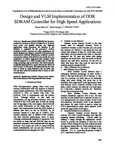
regular (less control intensive) parts of the image processing algorithms, leaving the more control intensive parts to be implemented on DSPs. We followed this second philosophy in a previous work when we developed a memow centric reconfigurable architecture for a commercial HDTV mixer application. The architecture used is shown in Figure 1 . The main problem of DRAM architectures is the long access latency. Current DRAM architectures (DDRAM, DirectRambus, . . ,) reduce the overhead due to this latency using burst access to several consecutive data words in a memory row. The effect of access latency can be fullhcr reduced by exploiting the internal bank structllre of a DRAM and switching to another bank while one bank is busy accessing. This technique, called interleaving, increases memory bandwidth, however without reducing the individual memory access latency. If there are enough banks, then the burst length and, hence, the individual access latency can be reduced without significant loss in memory bandwidth. This technique has already been utilized in the FPGA based memory controller of the HDTV mixer reaching on average 70% of the SDRAM peak performance with a burst length of only 4 words [SI. With even higher throughputs and more complex access patterns, the latency grows again due to larger intermediate buffers and ahigherschcdulercomplexity. In this paper, wc propose a two stage controller architecture consisting o f a bank scheduler that is adapted to the memory structure and a request scheduler that reflects the access patterns. We iwestigatc WOdifferent buffering and scheduling strategies that are simple enough to m n i n real-
time. Additional PUS(apt.)
using parallel DSP processors with interleaved memory access, rising large FPGAs for highly regular algorithms extended by DSP processors for less regular algorithms. Highspeed intermmecl bur
The first option requires many powerful DSPs to achieve the desired results, which leads to complex and expensive systems. The second option explores the fact that todays FPGAs have a very large amount of logic that can imvlement multivle arithmetic overations per clock-cycle. FPGAs can be used to implement the more I
~
Fig. 1. Flexible image processing platform ~~
’Thin resolutioii means 2048x1556 pixels per frame at 30 bitipixel and 24 picturesis resulting in 11.4 Mbytes memory requirements per frame
0-7803-7795-8/03/ $17.00 02003 IEEE
~~
After a concise introduction to requirements and related work
322
the two variants oftlie 2-stage memory controller architecture are described in section 3. Section 4 describes the SystemC based evaluation environment. the experimental setup and the results. S ection 5 draws a conclusion. 2. REQUIREMENTS AND RELATED WORK A closer look reveals that the following distinct types of accesses have to be served by the SDRAM controller:
.
Hard YS. soft realtime. While for some access sequences a maximum lantency inust be guaranteed, e.g. image streams which inlust not lose any pixel (hard real-time), other access sequences like user-interface CPU accesses might not suffer from a short stall (soR real-time). However, it has to be ensured that no acccss sequence gets completely blocked.
Fixed address patterns, like mage inpulloutput streams or data streams generated by FPGA-based processing accelerators. To increase troughput and to compensate the burstoriented SDRAM access, data prefetching and large FIFOs which arc needed for higher troughput can be used. Since these are usually hard real-time streams, a maximum latency and minimren troughput must be guaranteed.
Random address patterns, like DSP memory access in case of cache miss. Sincc these address patterns are nondeterministic. data prefetching cannot be used. Instead, to iniininiize stall timcs, these accesses should be served with s,iinllesr possible latency, therefore small buffers and short burst lengths should be used. Depending on the CPU task, these access sequences can be hard or soft real-time. Thc Iniagine processor [ I O ] uses a'configurable memory scheduler [ 5 ] . optimized for the application algorithms that run on the processor. The scheduler is adapted to a specific application and does not distinguish different stream types (hard-real time vs. sort-real-time). The Prophid architecture [7] by Meerbergen et al. describes a dynamic RAM scheduler forthe Prophid DSP platform that is focused on streams using large FIFO buffers and roundrobin scheduling. Thc "Center for Embedded Computer Systems" group at UCI [9] provides optimization heuristics far known memory access patterns of R single processor Finally, Sonics offcrs a memory schcduler IP 141 for their specific TDMA bus protocol. None of these schedulers support vastly different access types at close to peak SDRAM bandwidth.
3.1. 1st Variant: Request Priority Scheduling 3.1.1. Request Scheduler. Bank Buffer
Requests to the SDRAM controller are always made at full burst length. The Request Scheduler forwards requests of several inputs with different request types, one request per clock cycle, to the Bank Buffer. The bank buffer FlFOs are small FIFOs, one per bank, which store the requests sorted by bank. By applying a priority-based round-robin arbitration similar to [ I I], it i s guaranteed that successively each input gets scheduled (assuming a request is available and the according bank buffer is empty). Requests from high priority inputs are scheduled out of order before requests from standard inputs. To prevent standard priority requests from being blocked by continuous high priority requests, after a consecutive scheduling of all high priority inputs one standard priority request gets scheduled. Without loss of generality, we use 2 priority levels. 3.1.2. Bank Scheduler
The Bank Scheduler is responsible for selecting requests from the bank buffer and forwarding them to the tightly coupled Access Controller for execution. In order to increase bandwidth utilization, two aspects have to be considered bank inferleaving and request bundling. Bonk interleaving is used to hide the bank access latencies. In a common SDRAM setup, an access to a bank in auto-precharge mode and with burtstlength 4 takes 4 active cylces in which data is transferred, follwed by 4 (read) to 6 (write) passive cycles during which the bank cannot be accessed. However, during these passive cycles, another bank can be accessed. Thus, with at least 3 banks available, it can be guaranteed that each memory bank can be accessed once in a round without stalling. The scheduler maintains bank busy flags which describe the current state of the bank. By only selecting banks which are not bury and by applying a priority-based round-robin arbitration similar to [I I], it is guaranteed that successively each bank gets scheduled (assuming a request is available). Request bundling is used to minimize bus direction switches. On every bus direction switch, tristate cycles have to be inserted (1 for a read-write change, 1-2 for a write-read change, depending on the type of SDRAM) which can lead to a bandwidth decrease of up to 20..27% for alternating read-write accesses. Bundling requests to consecutive read or write sequence alleviates this. To prevent deadlocks, only one request ofeach bank is allowed in one read or write bundle.
3. ARCHITECTURE
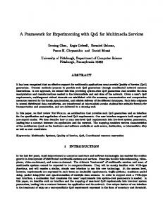
Our main design goal was to reach maximum memory bandwidth for multiple access streams with different access sequence types running in parallel. As explained in the introduction, the two abjeclives (iiinxinium bandwidth and minimum latency) require cantradictory buffer types and memory burst lengths. Fig.2 shows the overall memory controller stmcture with the two scheduler variants. one with a single buffer per bank and a second, sligthly more complicated architecture with different queues enabling access prioritization on a per bank level instead of only on the reqiicst level. In this paper, we focus on the two blocks, request schedulergndbmk scheduler. their respective hufiers and their scheduling strategies.
323
3.2. 2nd Variant: Bank Priority Scheduling 3.2.1. Request Schedule< Bonk Buffer
In this variant, independent pathes are provided for different request priorities. Each priority has got its own request scheduler and their own bank buffer FIFOs. Since the same arbitation scheme (without request priorities) is used as in the 1st variant, we still have a deterministic maximum latency and per-input troughput. As expained above, different bank buffer FlFOs for different priorities exist. A later multiplexor selects high priority requests if availa able, otherwise standard priority requests.. To prevent normal requests from being deadlocked by continuous high priority
Standard Prioriv: * standard latency * regular access patterns
I I
Request Buffer
......................
.
5
-
- --t
-......
Access
a
I Buffers -1
.' .......
I -'
~~~~~. w
Request Scheduler
M-
I ~ ~ t a g e I Scheduler ~
Bank Buffer
I 1
Bank
I
Request Buffer
Request Scheduler
Bank Buffir
Bank Scheduler
I I
I
~~~~~~~
.
I
:
+m+m-
2
Buffer
zZmFnyp-1 ......................
High priority: * reduced latency * unregular access patterns
Data
Addresstranslation
ports
! I
4
-
Variant 1
Dataflow Request flow
Variant 2
L-
I Standard priority
Example Setup:
High priority
--
4 bank memory 2 standard priority ports (1 read, 1 write) * 2 high priority ports (1 read, 1 write)
Fig. 2. SDKAM controller architecture huffer FIFO multiplexors select a standard priority request regardless of available high priority requests as stated above).
3.3. Additional Modules Since the rest o f the SDKAM controller i s the same i n both variants, they will he explained only once.
3.3.1. Access Conlmller 3.2.2. Bouk Scheduler The Bank Scheduler works similar to the Is1 variant regarding bank interleaving. request bundling and the rarind-robin arhitration scheme. In addition, the priority handling has moved from the requcst scheduler to the hank scheduler. To accomplish this, high priorily requests are given precedence over standard priority requests. Only if ,no high priority requests can h e scheduled, a standard priority request i s taken. To prevent standard priority requests from being blocked by continuous high priority requests, aRer a consecutive scheduling ILI,.,L.~ high priority requests one standard priority request gets scheduled if available (in this case, the bank
324
The Access Controller is responsible for SDRAM command issuing, including initialization and refresh cycles. As stated above, and contrary to most other SDRAM controllers, the SDRAM i s accessed using auto-precharge mode, which means that a bank i s automatically precharged after an access. This results i n deterministic hank throughput and access latency which is needed for a global real-time analysis. Also, the complexity o f the controller decreases due to a simpler state machine and lack o f row address comparators, which makes it more suitable for FPGAs. The Access Controller works with a burst length of 4 words (8 wards on DDR-SDKAM).
3.3.2. Address Translnrion
4.1. Experiment 1
Due to the nuto precharge mode, there is no advantage in mapping access sequences to the samebank and TOW to exploit row buffer hits as with precharge-based SDRAM controllers [ 121. In contrast, the latency increases iftwo consecutive requests hit the same bank. To avoid this. request sequences are spread over all banks by permutating and ror-ing original address bits analogous lo [14]. For many deterministic address patterns. e.g. linear address incrementation during video input, the optimum bank access sequence can be achieved by adapting the algorithm.
We created two random access, 50% read and 50% write streams, one "best effort" (BEF) stream with a fixed load and one "realtime" (RT) stream. Then we increased the load of the RT stream and tested for the first data loss on the RT stream. At this point, we recorded the current RT load, the yielded BEF load and the latencies for both RT and BEF streams. We did this test with several BEF loads, with and without higher priorities far the RT stream, with two different bank buffer FIFO sizes (1 and 6) and with both SDRAM controller architectures. For the bank buffer size of 6 and architecture 2, we split the 6 buffer entries in 3 high- and 3 standard priority FIFO entries (same as in experiment 1, 2x3 entries instead of 6). The results are shown in Table 1. We made the follwing observations: The access controller reaches a databus bandwith utilization of at most 90%. e The data bus utilization of the 1st architecture is about 5% higher compared to the 2nd architecture. Also, overall latencies are slightly higher on the 2nd architecture. This is due to the different architecture of the bank scheduler, which causes more readwrite switches in architecture 2. For high BEF loads, activating the priorities lowers the latency of the RT stream (Nr. I and 1 I compared to Nr. 5 and IO, for architecture 2 also nr. 8,12 to 6,1 I). This effect is bigger at architecture 2. For low BEF loads, activating priority only shows effect with small bank buffers (Nr, I compared to Nr. 3). Increasing the data buffer leads to an overall increase of latency. e Increasing the data buffer size shows a slightly higher databus utilization (Nr. 1,3,5,7,9,11 compared to 2;4,6,8,10,12). Small bank buffer FIFOs might cause new requests being stalled in the request buffer if those would go to the same bank buffcr FIFO. Subsequent requests which might go to a different bank thus cannot be scheduled. In turn, less requests to different banks are available at the bank scheduler which leads to an overall performance loss. Increasing the data buffer size alleviates the effect of the priorities for the 1st architecture (Nr. 5,7,9,11 compared to 6,8,10,12). The reason is, that, once high priority request are in a deep bank buffer, they receive the same latency as standard priority requests. This cancels the effect of the prioritized request scheduler
3.3.3. Doto B@r The writwequest data gets stored inside data buffers. Once the request has been scheduled, the data is transferred to the SDRAM. For read rcqoests, an empty place in the according data buffer is assigned to the reqoest. If the read is executed, the data from the SDRAM is transferred lo that place. The bank buffer access is done via tags which are assigned to the requests. This technique allows an easy adaptian of the off-chip SDRAM databus width and the usually malle er intynd datapathes. It also alleviates the need lo store the data inside the buffer FlFOs and the buffer-to-buffer transfers.
3.4. Real-Time Aspects Since all scliedulers use round-robin arbitration, and deadlocks due to continuous high-priority requests are prevented by temporarily forcing the scheduling of law-priority requests, we have a deteministic maximum latency and ininiinum troughput
3.5. Parameters The ~ o n t r ~ l l is e r parameterizable lo serve different applications. The iiiost iimportant parameters are the SDRAM layout (rows, colunm, banks) and timing, number of inputs including their priority and thr FIFO sizes. Those parameters directly influence the latcncy and throughput, Increasing the number of inputs increases the iiiaximiiiii per-port latency and decreases the per-port maximiim troughput (decrease of performance). Increasing the number of banks also increases the per-bank latency and decreases per bank troughput which in turn also affects the worst case performance. I.IoweveI; inlare banks also increases the possibility that two requests get mapped to different banks which leads to a better average performance. However, if the bank access sequence can be predicted as stated in 3.3.2, then also the worst-case performance is iniproved.
4.2. Experiment 2 While the synthetic experiment 1 gives a good impression of the memory controller performance, we are also interested in the performance under practical conditions. For this purpose, we defined an example architecture which ressembles the setup in [8] and implemented an example application. The experimental setup is shown in fig. 3. It consists of a hardware implementation of a discrete wavelet transformation (DWT) algorithm and a CPU with caches (Figure 3).
4. EXPERIMENTS To evaluate the concept, we created a system modcl consisting of the SDRAM, SDRAM controller as well as ~everalclients. We used SysternC for implementation because, besides the high simulation speed, it allowed us to model at serveral abstraction levels 111 nile langiiage and 10 easily reuse available C models. For speed reasons, the SDRAM controller and SDRAM model were inipleinented at cycle-accurate transaction level, except for lhe interface betwcen controller and SDRAM which is at RTL.
4.2.1. Discrete Wovelet Transformorion
The DWT implementation is based on [I31 and was implemented in SystemC at the RT-Level to obtain a cycle true simulation
325
0.2 0.2
11
size
1
612x3
11
nn
/I
I
96 95 97 95 97 94 97 95 97 94 97
I
612x3 1
612x3 1 6/2x3 I 612x3 1 612x3
0.5
I
Architecure variant 1 II Architecure variant 2 Throughput Latency Throughput Li total I RT I BEF RT I BEF total I RT 1 BEF RT
I076 0.75 0.77 0.45 0.5
0.5 0.5 0.25 0.2 0.4 0.3
I
0 2 154 0.2 38 0.2 57 38 0.5 0.47 87 0.44 31 0.47 76 0.7 32 0.77 84 0.54 30 91 0.67
I
54 56 57 39 86 58 85 50 90 66 107
11
1
91 90 91 89 92 90 91 90 92 90 92
IO71 0.7 0.71 0.45 0.45 0.44 0.5 0.4 0.34 0.46 0.5
I
02 I34 0.2 37 0.2 38 0.45 62 0.47 78 0.46 20 0.41 27 0.5 42 0.58 67 0.44 20 0.42 27
82 133 94 IO0
c - cycles RT pri -real time prioritizing yesho BB size -bank buffer FIFO size
wlc - words per cycle BEF - Best Effon RT -Real-time
Table 1. Experiment 2; real-time
YS.
best effort
the FPGA are relatively large. This way, the fixed access pattern can be served by burst memory access. The data VO for the DWT uses a separate port, DWT 110.This port reads and writes a periodic pixel stream.
.
SDRAM Controller
4.2.2. CPU
Cache
For CPU simulation, the SimpleScalar SimSafe DLX simulator together with an adaptation of the Dinera cache simulator were used. The CPU has its own fast local RAM for program code and local variables (stack) and uses the SDRAM for larger data storage. In the final system, the CPU will be replaced by a D SP, but this architecture is suf6cient to generate meaningful burst cache access patterns for these experiments.
I[@
4.2.3. Simulation Results
The DWT was setup for a three level 512 x 512 grayscale image, and the CPU performed a compression of a 64 x 64 color image using cjpeg from the media testbench [6]. The SDRAM controller was clocked at 140 MHz, the DWT at 100 MHz, which the CAD tools indicated is reachable with our FPGA configuration. The CPU and the cache (2Kb, 4-way associative, block size equal to SDRAM burst length) were clocked at 1 GHz to compensate for the weak DLX performance (as said in Subsection 4.2.2 ideally we would use a powerful DSP instead). The SDRAM was an 8 bank, 64 MB module. We measured the execution time of the DWT and the CPU for several NUnS with the following parameters:
Fig. 3. Experimental setup
model and B basis far a precise cost and performance estimation via logic synthesis. After synthesis followed by place and route for a Xilinx Virtexll FPGA. the CAD tools reported a maximum operating frequency of 100 MHz. This frequency is not a integer fraction ofthe expected 140 MI-lz SDRAM memory interface clock. So in order to achieve niaximum throughput we used asynchronous FlFOs to transfer data between the two different clock domains. The DWT input consumes one data item (2 pixels) per clock cycle, while the four outputs are idle for 8 cycles, followed by 8 cycles of data output through 4 pnrallcl write parts. The period of the output streams depends on the image width and on the current DWT level [13]. Because this algorithm, as well as most other image transform or filtering algorithms, have a known memory access pattern, we are able to apply pre-fetching to all inpiit data. This is aided by the fact that the avaliable FlFOs on
Running only CPU, only DWT and both CPU and DWT. Bank buffer FIFO size of I YS. 6 . For architecture 2, we set a) both high and standard priority FIFOs to 6 (2x6) and b) both high and standard priority FlFOs to 3 (2x3). The later (2x3) sizes have about the same complexity as a single FIFO of size 6. The results are shown in table 2. We made the following observations:
326
BB
Architecture 1 CPU DWT I 5.75 (1.89)
504 6 7
1
8
yes yes yes
I
no yes yes
I 612x3 /I I 612x6
CPU
An itecture 2 DWT Mcycles / CPI 5.75 (1.89) 5.75 (1.89) 5.75 (1.89) 504 504 504
531 532
6.75 (2.22) 6.76(2.22)
531 538
CPU pri - CPU prioritizing yeslno BB size -bank buffer FIFO size
I: 6.61 (2.17) 6.63 (2.18) 6.63 (2.18)
Table 2. Experiment 1: Simulation setup and results
a Architecture 2: setting the bank buffer FIFO size to 2x3
[6] CHUNHOLEE, MIODRAGPOTKONJAK,W. H. M . A . Mediabench: A tool for evaluating and synthesizing multimedia and communicatons systems. In Inrernationol Symposium on Microarchitecture (1997), pp. 330-335.
shows no difference compared to the 2x6 setting (nr. 2,5,8 vs. 3.6,9) The mutual influence of CPU activity and DWT is small, despite the relatively large load and despite the very different access patterns. This is a result of the flexible 2 stage scheduling scheme with short access bursts and small round-robin time slots leading to low latencies.
[7] JEROENA. I. LEITJEN,JEF L. VAN MEERBERGEN, A. H. T. Prophid: A heterogeneous multi-processor architecture for multimedia. In International Conference on ComputerDesign (October 1997), pp. 164-169.
IS] KERSIEN HENRISS,PETER RUEFFER, R. E. A reconfigurable hardware platform for digital real-time signal processing in television studios. In Proceedings ofIEEE Symposium on Field-Programmable Custom Computing Machines (April
5. CONCLUSION
Based on earlier experience with a fixed architecture for a reconfigurable HDTV system, we presented two variants of a dynamic RAM scheduler IP that supports several concurrent access sequence types with different requirements including hard real-time periodic scquences and cache accesses with a minimum latency objective. It consists of a 2-stage scheduler, a Bank Scheduler for memory efficiency optimization and a Request Scheduler to arbitrate the access streanis. We explained the two variants, the chosen IP parameters and their impact on design performance. The IP has been evaluated in a simulation environment consisting of a processor with cache, an application specific data path for wavelet coding and vidco 110,all implemented in SystemC. In the evaluation, we demonstrated the high flexibility and efficiency of the 2-stage approach. The sinidation data show a 90% memory bandwidth utilization and adherence to access requirements for a wide range of load scenarios. The IP can easily be adapted to DDR-RAM or RAMBUS DRAM by simply exchanging the memory interface and the bank model.
6. REFERENCES [I] bttp:l/www.discreet.cbm [2] http://www.quantel.com.
[3] littp:l/www.thomsanbroadcast.com.
moo).
[9] PRABHATMISHRA, PETER GRUN, N . D. Processormemory co-exploration driven by a memory-aware architecture description language. In 14th International Conference on VLSI Design (Jan 2001). [IO] UJVAL J . KAPASI, WILLIAM I . DALLY, S. R. The imagine stream processor. In Inrernational Conference on Computer Design (2002). [ I I] WEBER,M. Arbiters: Design ideas and coding styles. In SNUG, Boston (2001).
[I21 WEI-FENLIN, STEVEN K. REINHARDT, D.B. Designinga modem memory hierarchy with hardware prefetching. IEEE Transactions on Computers 50, I 1 (November 2001). 12021218. [I31 WU, P.-C., AND CHEN, L.-G. Anefficientarchitecturefor two-dimensional discrete wavelet transform. IEEE Transactions on circuits and systems for video technologv 11, 4 (April 2001). [I41 ZHAO ZHANG, ZHLCHUN ZHU, X. Z. A permutation-based page interleaving scheme to reduce row-buffer c o d i c t s and exploit data locality. In Inrernarionol Symposium on Microarchitecture(2000), pp. 3 2 4 1
siliconbackplane micronetwork overview. hti~~://~~~vwn:sonicsi,Ic.comlsonics/p~~d~~~s/sili~~~b~ckpl~~~.
[4] Sonics
[SI B R U C E K KHAILANY, WILLIAM 1. DALLY,S. R. Imagine: Media processing with streams. 3 5 4 6 .
327