373
A Model-driven and Knowledge-based Methodology for Engineering Design Change Management Genyuan Fei1, James Gao1, Dele Owodunni1 and Xiaoqing Tang2 University of Greenwich,
[email protected] Beihang University,
[email protected]
1
2
ABSTRACT Change management is very important to the success of new product development. The earlier that change issues are addressed, the greater that product lifecycle costs can be saved. This paper presents a novel methodology that has been developed to help designers trace, analyse and evaluate engineering changes occurring in the product design phase. A modelling method is employed to enhance the traceability of potential design changes occurring between the functional and structural domains of design. Based on functional and physical models, a matrix is developed to analyse change propagations and help identify design conflicts arising from design changes. A knowledge based methodology has been developed to resolve design conflicts by reusing previous design change knowledge. A wind turbine for power generation from the collaborating company is used to evaluate the developed methodologies. Keywords: engineering change, design conflict resolving, knowledge management. DOI: 10.3722/cadaps.2011.373-382 1
INTRODUCTION
Engineering changes have been recognised as inevitable in complex engineering product development [1, 2]. They have great influence on downstream developing and production activities, making product development very costly and time consuming. Therefore, it is critical to keep them under control. On the other hand, engineering changes have also been recognised as a source of innovation and creativity which can facilitate evolutions of products and technologies [3-4]. From this perspective, knowledge acquired from engineering changes is also very useful to product development in the long term. Significant research has been reported in engineering change management (ECM) regarding computerising traditional paper-based engineering change processes [5], improving communication methods between engineers [6], clarifying knock-on change effects between components [7]. Most early research shows the efforts made in dealing with engineering changes in the manufacturing process. More recently, international research effort has been focusing on managing changes in the early stages of product lifecycle, as effects in the design stage may significantly cause increase of the total development cost. One of the most important issues in change management is change propagation which often leads to great complexity by spreading knock-on effects via dependency relationships between design elements. Some methods have been proposed trying to predict change propagations and analyse their potential impacts on other parts of the system [8]. However, engineering changes Computer-Aided Design & Applications, 8(3), 2011, 373-382 © 2011 CAD Solutions, LLC, http://www.cadanda.com
374
always propagate dynamically, which means that it is difficult to predict change propagations and how the dependency relationship within a system will change until the solution for the preceding change is determined. The complexity of engineering change analysis means that designers could be easily exhausted before having investigated the entire design space. Some IT systems have been developed to help designers by computerising the traditional ECM process [5], integrating with other manufacturing systems to enhance communications, and visualising change propagation tracking [9]. However, there is a lack of tools for resolving design conflicts arising from change propagations using previous design experience. It should be noted that engineering change management has been an important part of product lifecycle management (PLM). Researchers have developed and used PLM technologies to manage the information, knowledge and business processes related to a product in its whole lifecycle (e.g., a leading research group in features reported a PDM-based framework for collaborative aircraft design [10,11]. This project aims at dealing with changes in the functional domain and the physical structure domain of complex product design. It would help designers analyse design change propagations within these two domains. It would also help to resolve design conflicts arising from design changes using knowledge from previous design change cases. There are mainly three objectives, i.e., (i) dynamically capture changes and their propagations between functional requirements and physical components; (ii) identify and formalise design conflicts arising from design changes; and (iii) use knowledge based engineering (KBE) technology to facilitate finding solutions for design conflicts from previous design cases. 2
DESIGN CHANGE PROPAGATION ANALYSIS AND CONFLICT IDENTIFICATION
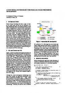
An important argument brought forward in this research is that Change propagation is caused by design conflict that occurs when a change of a part of the system obstructs or harms realisations of the functions of other parts. Design conflicts are quite common in product development, while designers work on respective parts of a system and do not have a complete picture of the dependencies between each part in early phases. However, even if the system has been successfully put together, design conflicts still happen when some parts of the system change. Although a lot of methods have been proposed to predict change propagations in engineering change management, there is a lack of methods for formalising the change propagation chain. When considering design conflicts arising during change propagations, the dependencies between design elements should be further analysed. The change propagation process can be broken down as shown in Fig. 1 so that the impact of each phase of the propagation chain can be analysed effectively.
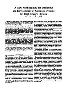
Fig. 1: Process of change propagation analysis. When the initial change is determined, designers need to analyse whether the result of this change may obstruct or harm realisations of functions of other parts of the system. If it does, then further changes need to be carried out. These are the so-called propagated changes. If it causes no negative influences on other parts and they can function well as designed, then change propagation ends. The cooling system of a new wind turbine (Fig. 2) is used in this project to evaluate the proposed methodology. This product is being developed by the industrial collaborator which is a pioneer in gearless wind turbine development. Nearly 2000 wind turbines (by May 2010) based on their solutions have been deployed in Europe, Asia and America. An example change in design requirement is that a customer needs the wind turbine to be deployed in particular sandy environments, and the air filtering of the cooling system needs to be much improved to prevent heavy sands coming to the cooling system. This change causes some knock-on effects that give rise to changes on other parts of the system. The methodology proposed in this paper aims to solve this problem by modelling the cooling Computer-Aided Design & Applications, 8(3), 2011, 373-382 © 2011 CAD Solutions, LLC, http://www.cadanda.com
375
system, identifying design changes and related design conflicts, and resolving the chosen design conflicts using a knowledge-based system.
Fig. 2: An inside view of the wind turbine (Courtesy of Vensys AG Engergy). 2.1
Functional and Physical Dependency Modelling
Before going into design change propagation analysis, it’s important to clarify dependent relationships between elements of engineering design. Elements of an engineering design considered in this project include functional requirements in the functional domain, and physical components in the physical domain. Consequently, dependent relationships include dependencies between functional requirements, involvement of the physical components for the realisations of functional requirements, and interactional and spatial relationships between physical structures. The block definition diagram (BDD) of SysMLTM [12] is used to model the functional requirements (Fig. 3a), the internal block diagram (IBD) of SysMLTM is used to model the interactional relationships between physical components (Fig. 3b), and the CAD geometric models are used to clarify spatial relationships between physical components. The composite matrix proposed in the following section summarises the interactional relationships depicted in Fig. 1 (b). It also clarifies the mapping relationships between functional requirements and physical components, and the spatial relationships between physical components.
Fig. 3: Modelling methods for functional and physical dependencies. 2.2
The composite Matrix for Design Change Propagation Analysis
A matrix based method is employed to analyse change propagations within and between functional requirement domain and physical structure domain. A composite matrix (see Fig. 4) is constructed based on the results of modelling analyses of functional structure, physical interaction and physically spatial relationship. The matrix is composed of three parts which are marked by different colours. The first part (the green part) represents the mapping relationship between function and components. Elements in the first column represent physical components, and elements in the green part of the Computer-Aided Design & Applications, 8(3), 2011, 373-382 © 2011 CAD Solutions, LLC, http://www.cadanda.com
376
first row represent functions. Each marked cell in the green part represents the involvement of a component in the realisation of a function. The second part (the blue part) represents the interaction relationship between components, which reflects the modelling results of physical interactions between components. Elements in the first row of the blue part represent flows in Fig. 3(b). When there are changes happening on a component (an element in the first column), related flows going through it will be identified in the matrix. Components that these flows go through are also identified. The third part (the grey part) represents the physically spatial relationship between components. A marked cell in this part the matrix means the component in the column is physically connected with the component in the row. Clarification of this type of relationsh relationship ip helps designers find potential propagating changes to neighbouring components. mponents. Although in some research, matrix-based based methods have been discussed for static dependency analyses between physical components in product design, this proposed composite matrix ix can be useful to dynamically analyse dependencies between the functional domain and physical domain of product design and facilitate change propagation capture. The process of how to use the composite matrix has been discussed in section 2.3.
Fig. 4: Composite matrix for change analysis analysis. 2.3
Process of Design Change Propagation Analysis and Design Conflict IIdentification
This section clarifies the idea of analysing change propagations and identifying design conflict arising from change propagations. The method od is described in association with a special customer requirement (i.e., a change) of improving the air filtering measure mentioned above and is based on the composite matrix for change analysis (Fig. Fig. 4 4). The change is triggered ered by a functional requirement called ‘F2: Filter hot air’. The e analytical process starts from the function function-component omponent part of the matrix. matrix Step 1: Identify component changes caused by functional change. As mentioned above, because of the sandy environment where the wind turbine will be deployed, the current air filtering measure cannot meet the requirement. Fig. 4 shows components involved in the realisation of function, filt filter er hot air (F2). Only one component C2 is identified. To meet the sandy environment, the current air filter mat with a dust holding capacity 650g/m2 needs to be increased to 750g/m2. Step 2: Identify potential affected components. The component changed in the above step may change the physical statuses of flows going through it and may also change its neighbouring components due to changes of its spatial characteristics. Led by component C2, the row shows flows and neighbouring components that are potentially affected by the change of C2. In this case, flow FL1 and neighbouring component C1 are related to C1. The flow FL1 also goes through C1, C3, C4, C5, so these 4 components may also be potentially affected by th the change of C1. The side effect of changing Computer Computer-Aided Design & Applications, 8(3), 2011, 373-382 382 © 2011 CAD Solutions, LLC, http://www.cadanda.com
377
the air filter mat is that the mat with higher dust holding capacity is thicker and causes larger air pressure drop, which can significantly reduce the efficiency of heat exchanging. Step 3: Check change effects with related functions. Components that are affected by the flows and the spatial connections need to be checked whether the changed flows or the changed spatial connections would affect the realisations of their related functions. In this case, the air flow after the filter mat has a lower pressure which means components C3, C4 and C5 would be potentially affected since the status of air through them is changed (see the column led by FL1). According to the analysis by engineers, the lower air pressure through C3 will weaken its performance. Also the lower air pressure through C4 will reduce the efficiency of heat exchange. But it has almost no effect on C5. The spatial change (thicker filter mat) has been considered as not noticeable change on C1 since the change can be easily accommodated by the current design. Although in this case change caused by spatial connection is negligible, in many other cases it may be significant and corresponding changes need to be made. For example, in this case, change the component C1 or add some other structures to accommodate the changes caused by spatial connections. Therefore, C3 and C4 have been identified as affected components which need to be changed to accommodate negative impact from the previous change on C2. Step 4: Identify and solve design conflicts. By analysing affected components, design conflicts can be identified. Taking C4 as an example, the changed input flow is the incoming air (FL1). Its pressure is lowered due to the change of the air filter mat (C2) and the affected parameter is the heat exchange efficiency which is also lowered. This effect means the heat exchange cannot meet the functional requirement F4. Therefore this design conflict needs to be solved. A knowledge based method is developed to help designers find reference solutions from previous design cases. The ways of formalising design conflict and reasoning in the knowledge base have been presented in the next section. Step 5: Analyse change propagations caused by component changes in step 4. When a proper solution has been found in step 4, changes on affected components have been determined. These changes would potentially affect other components as well in form of design conflict. In the above case, if component C4 has been changed flows FL1, FL2 and connected components C2, C6 may also be potentially affected. Thus, a next round of change analysis also needs to be carried out until there is no further change conflict being identified, which means change propagation stops and change analysis initiated by the first change can be finished. 3
KNOWLEDGE-BASED DESIGN CONFLICT RESOLVING
The contradiction matrix and invention principles of TRIZ have been used by many companies to resolve technical conflicts [13]. The idea of TRIZ to solve conflicts includes generally four steps: (1) identify technical conflicts; (2) generalise technical conflicts by using 39 engineering parameters; (3) find invention principles via a standard contradiction matrix; and (4) explore specific solutions by following the indications of invention principles. Although problem solving techniques of TRIZ are innovative and inspirational to engineers, the method is difficult to master without comprehensive training and long-time experience. The authors proposed a knowledge-based method which works in a similar way but more intuitive and easier to use. Fig. 5 depicts the process of how design conflicts have been solved.
Fig. 5: Process of resolving design conflicts. Computer-Aided Design & Applications, 8(3), 2011, 373-382 © 2011 CAD Solutions, LLC, http://www.cadanda.com
378
Design conflicts, identified through the matrix-based design change propagation analysis, need to be formalised and generalised with predefined ontology which is also the basis of the knowledge system. Fig. 6 shows the formalisation of a design conflict caused by flows. A flow-caused design conflict includes physical components where the conflict happens, the changed input flows that cause the conflict and affected output flows that are affected by the changed input flows. Both the input flows and the output flows are formalised by the flow ontology and the characteristics ontology. The flow ontology defines the type of the flow. The characteristics ontology defines the key properties of a flow. For example, the gas flow normally has properties like pressure, temperature and moisture. Properties formalised in this part should be critical to the operation of the component. The behaviour ontology defines how the flow is changed, which is used with the characteristics and/or other flows or objects. The component is formalised by the functional ontology. The functional ontology defines what the component does and what object the component uses while it operates. The characteristics are critical for the performance of the operation of the component. For example, in the cooling system, there are two characteristics of the heat exchanger are important to its functionality. One is the area of the heat exchanger surface. Wider surface can have higher heat exchanging efficiency. The other one is the material that the heat exchanger is made of. Some material, for example bronze, has a better heat conduction performance than others (e.g., steel).
Fig. 6: Formalisation of design conflicts. The functional ontology used, so called functional basis, contains generalised functions and flows which are regarded as a useful and comprehensive engineering functional ontology. The functional ontology includes behaviour ontology and flow ontology. Domain ontology is also developed to classify products, subsystems and components used in the wind turbine. Protégé is used as an ontology editor to develop the proposed ontology. Protégé was developed by Stanford University and is the de facto in the academic community for ontology development. Fig. 7 shows some parts of the ontology, including definitions of flows, definitions of functions, definitions of product components and an instance of a flow in the cooling system.
Fig. 7: Ontology developed for engineering design change. Computer-Aided Design & Applications, 8(3), 2011, 373-382 © 2011 CAD Solutions, LLC, http://www.cadanda.com
379
When a design conflict arising from design change analysis, it is formalised and generalised by using defined ontology to specify the essences of input flows, output flows, and functionalities. The generalised model of the design conflict will then be pushed into the knowledge system. The system will reason in the knowledge repository by analysing the semantic similarities between different concepts to find most similar functional and physical descriptions. After that, solutions attached to these descriptions will be retrieved as reference solutions for the current design conflict. Designers can adjust or adopt similar solutions to solve current problems. The framework of knowledge based system for design conflict resolving is shown in Fig. 8. In this system, design cases are collected from many sources including different functional departments and IT systems. The design cases are formalised in a hierarchical way, which clarifies functions or problems a design case is to address, the solutions used in this design case, the components involved in this solution and characteristics that contribute to the realisation of the function or the problem solving. The formalised structure is also been generalised by domain ontology including behaviour ontology, flow ontology, subsystem/component ontology and physical characteristic ontology. Therefore, a design conflict generalised by the same set of ontology is able to find reference solutions by comparing semantic similarities and retrieve related and useful previous design cases.
Fig. 8: Knowledge repository building using previous design cases. A three-tier web-based prototype system is developed implement knowledge-based system for engineering design change management. Software systems involved in this prototype include MySQL as an infrastructure of data storage, Tomcat 6.0 as a web server and servlet container, Java enterprise edition (Java EE) as the business implementation architecture, and also Java Server Page (JSP) as a presentation technology. Protégé is deeply used to edit ontology, convert and store ontology into a relational database. Integrations with other business systems like PDM, ERP and SCM are going to be done at the next stage of this research. 4.
REASONING METHOD FOR DESIGN CONFLICT SOLVING
The reasoning method is critical to finding candidate solutions for design conflicts arising from design change propagation analysis. It works with generalised design conflicts and the knowledge repository. Both are formalised based on the predefined set of ontology. The reasoning method is basically composed of two steps: (i) The generalised design conflict is used to compare with formalised design cases stored in the knowledge repository and find semantically similarly general solutions; and (ii) experienced engineers review retrieved design cases associated with general solutions to find the most viable ones. The general approach to solving design conflicts is depicted in Fig. 9. In the proposed reasoning methodology, one of the most important steps is to analyse semantic similarities between generalised design conflicts and general solutions stored in the knowledge repository. As described above, design conflicts are generalised by predefined ontology and also previous design cases are formalised using the same set of predefined ontology. If a design conflict is defined as a definition (D) and all of the stored general solutions are defined as a set {ܦଵ … ܦ }, the first
Computer-Aided Design & Applications, 8(3), 2011, 373-382 © 2011 CAD Solutions, LLC, http://www.cadanda.com
380
step is to find the most similar solutions from the set of general solutions. Both the design conflicts and the general solutions are formalised by the same set of ontology. Each element of the design conflict and the design case is tagged by an ontological concept of the predefined set of ontology (a node in the hierarchical structure). The algorithm of calculating the semantic similarities between a generalised design conflict and general solutions is comparing the semantic similarity of each corresponding element (e.g. the flow type of the changed incoming flow in Fig. 6) and then adding them up to get an overall semantic similarity.
Fig. 9: Reasoning approach to design conflict solving. Fig. 10(a) represents hierarchically ontological definition of a group of concepts. The higher of levels a concept stays in, the more general semantic meaning it represents. While in lower levels, the semantic meaning of a concept is more specific. In Fig. 10(b), IC(S1) represents the semantic meaning of the concept S1. Since S1 is the parent of S11 and S12, S1 has a wider semantic meaning than S11 and S12, which means: ܵ(ܥܫ11) ∈ ܵ(ܥܫ1), ܽ݊݀ ܵ(ܥܫ12) ∈ ܵ(ܥܫ1) (1) Theoretically, the following equation can represent how S11 (a child) is semantically similar to S1 (a parent) by comparing scales of semantic meaning of each concept: ܵ݅݉ (ܵ11, ܵ1) = ܵ(ܥܫ11)/ܵ(ܥܫ1) (2) While the similarity of S11 (a brother) to S12 (a brother) can be represented as: ܵ݅݉ (ܵ11, ܵ12) = (ܵ(ܥܫ11) ∩ ܵ(ܥܫ12))/ܵ(ܥܫ12)
(3)
Thus, the similarity of any two concepts (for example, S111 and S22) can be represented as: ܵ݅݉ (ܵ111, ܵ22) = {ܵ݅݉ (ܵ111, ܵ11) × ܵ݅݉ (ܵ11, ܵ1) × ܵ݅݉ (ܵ1, ܵ2) × ܵ݅݉ (ܵ22, ܵ2)} (4)
While in reality, it is well-known that exact semantic meaning of a concept is very difficult to measure. More often, people can tell the qualitative similarity between two concepts by their experience and common sense. So in this research, a survey is developed and experienced engineers are asked to rate semantic similarities between child-concepts and their direct parent-concepts (e.g. ܵ݅݉ (ܵ11, ܵ1)), and also between their brother-concepts (e.g. ܵ݅݉ (ܵ11, ܵ12)).
Fig. 10: Ontology definition and information content. Computer-Aided Design & Applications, 8(3), 2011, 373-382 © 2011 CAD Solutions, LLC, http://www.cadanda.com
381
Based on the ideas of rating and calculating similarities between concepts, the generalised deign conflict can be compared with general solutions in the knowledge repository, since both of them are formalised using the same set of ontology. The formalisation of general problems that general solutions intended to solve is the same as for design conflict formalisation. So the similarity between a generalised design conflict and a general problem can be described as: ܵ݅݉ (ܥܦ, = )ܲܩ൛ܵ݅݉ (ܨܥ , ீܨܥ ) × ܵ݅݉ (݊݅ݐܿ݊ݑܨ, ீ݊݅ݐܿ݊ݑܨ ) × ܵ݅݉ (ܨܣ , ீܨܣ )ൟ
(5)
Where DC represents design conflict, CF represents general problem, CF represents changed flow, and AF represents affected flow. Similarity between changed flows can be represented as: ܵ݅݉ (ܨܥ , ீܨܥ ) = ܵ݅݉ ( ݓ݈ܨ , ீ ݓ݈ܨ ) × ܵ݅݉ (ܥℎܽݎ݁ݐܿܽݎ, ܥℎܽீݎ݁ݐܿܽݎ ) (6) Similarity between functions can be represented as:
ܵ݅݉ ൫݊݅ݐܿ݊ݑܨ, ீ݊݅ݐܿ݊ݑܨ ൯= ܵ݅݉ (݁ܤℎܽݎݑ݅ݒ, ݁ܤℎܽீݎݑ݅ݒ ) × ܵ݅݉ (ܱܾ݆݁ܿݐ , ܱܾ݆݁ܿீݐ ) × ܵ݅݉ (ܥℎܽݎ݁ݐܿܽݎ , ܥℎܽீݎ݁ݐܿܽݎ ) Similarity between affected flows can be represented as: ܵ݅݉ (ܨܣ, ீܨܣ ) = ܵ݅݉ ( ݓ݈ܨ , ீ ݓ݈ܨ ) × ܵ݅݉ (ܥℎܽݎ݁ݐܿܽݎ, ܥℎܽீݎ݁ݐܿܽݎ )
(7) (8)
By comparing the overall similarities between the generalised deign conflict and general problems, a set of prioritised similarity values are generated: {ܵ݅݉ (ܥܦ, ܲܦଵ), ܵ݅݉ (ܥܦ, ܲܦଶ), … , ܵ݅݉ (ܥܦ, ܲܦ )}
By exploring and reviewing design cases associated with general problems (corresponding to general solutions) from higher priority to lower priority, the suitable design cases are chosen as reference solutions for the target design conflict. An example of resolving the design conflict identified in the section of change propagation analysis has been developed using the proposed reasoning method. The result is presented in a tabular form in Fig. 11.
Fig. 11: Example for design conflict resolving. 5
CONCLUSIONS
Any design changes either in functional requirement domain or in the physical structure domain will potentially affect operations of other parts. Change propagations and their impacts are difficult to capture, which makes product design in uncertainty. The authors argue that design change propagation is caused by deign conflicts arising from the initial and consequent changes which are difficult to predict without knowing their preceding change solutions, since all the following changes Computer-Aided Design & Applications, 8(3), 2011, 373-382 © 2011 CAD Solutions, LLC, http://www.cadanda.com
382
are based on the solutions of preceding changes. Knowledge from previous design change cases is an important asset for companies. Many design conflicts arising from change analysis can be tackled by reusing well-formalised and managed knowledge abstracted from previous design cases. In this paper, a methodology for design change management has been proposed to implement these ideas using modelling method, matrix analytical method and knowledge based engineering. First, the system engineering modelling method captures dependency relationships in and between functions and components. The matrix-based analytical method helps to trace change propagations and identify design conflicts by following mapping relationships between functions and components, and behavioural and spatial connections between components. Using the design conflicts formalisation approach, design conflicts can be formalised based on functional ontology, system/component ontology and physical characteristic ontology, which makes knowledge reasoning in the knowledge repository possible. The framework of the knowledge repository is proposed to collect knowledge of design change from previous design cases. With help of the knowledge repository and the reasoning method, designers are able to find proper solutions for design conflicts occurring in design change propagation. REFERENCES [1] [2] [3] [4] [5] [6] [7] [8] [9] [10] [11] [12] [13]
Huang, G.Q.; Yee, W.Y.; Mak, K.L.: Current practice of engineering change management in Hong Kong manufacturing industries, Journal of Materials Processing Technology, 139(1-3), 2003, 481487. doi:10.1016/S0924-0136(03)00524-7 Keller, R.; Eckert, C.M.; Clarkson, P.J.: Using an engineering change methodology to support conceptual design, Journal of Engineering Design, 20(6), 2009, 571 587. doi:10.1080/09544820802086988 Balogun, J.; Jenkins, M.: Re-conceiving Change Management: A Knowledge-based Perspective, European Management Journal, 21(2), 2003, 247-257. doi:10.1016/S0263-2373(03)00019-7 Eckert, C.; Clarkson, P.J.; Zanker, W.: Change and customisation in complex engineering domains, Research in Engineering Design, 15(1), 2004, 1-21. doi:10.1007/s00163-003-0031-7 Huang, G.Q.; Yee, W.Y.; Mak, K.L.: Development of a web-based system for engineering change management, Robotics and Computer-Integrated Manufacturing, 17, 2001, 255-267. doi:10.1016/S0736-5845(00)00058-2 Shiau, J.-Y.; Wee, H.M.: A distributed change control workflow for collaborative design network, Computers in Industry, 59(2-3), 2008, 119-127. doi:10.1016/j.compind.2007.06.010 Ariyo, O.O.; Eckert, C.M.; Clarkson, P.J.: Challenges in identifying the knock-on effects of engineering change, International Journal of Design Engineering, 2, 2009, 414-431. doi:10.1504/IJDE.2009.030821 Kocar, V.; Akgunduz, A.: ADVICE: A virtual environment for Engineering Change Management, Computers in Industry, 61(1), 2010, 15-28. doi:10.1016/j.compind.2009.05.008 Ouertani, M.Z.; Gzara, L.: Tracking product specification dependencies in collaborative design for conflict management, Computer-Aided Design, 40(7), 2008, 828-837. doi:10.1016/j.cad.2007.07.002 Li, Y.G, Ding, Y.F., Mou, W.P. and, Guo, H., Feature recognition technology for aircraft structural parts based on holistic attribute adjacency graph, Proceedings of the Institution of Mechanical Engineers, Part B, Journal of Engineering Manufacture, 2010, 224(2):271-278 Li, Y.G., Pan, Z.Y., Yan, R.J. and Liao, W.H., A PDM-based framework for collaborative aircraft tooling design, International Journal of Production Research, 2008, 46(9): 2413-2431 Object Management Group. OMG Systems Modeling Language (OMG SysML) V1.1. 2008, http://www.omg.org/spec/SysML/1.1/PDF. Altshuller, G.S.: And suddenly the inventor appeared : TRIZ, the theory of inventive problem solving, Worcester, Mass., 1996.
Computer-Aided Design & Applications, 8(3), 2011, 373-382 © 2011 CAD Solutions, LLC, http://www.cadanda.com