Proceedings of the International Multiconference on Computer Science and Information Technology, pp. 609 – 615
ISBN 978-83-60810-22-4 ISSN 1896-7094
MD Wizard – a Model-Driven Framework for Wizard-Based Modeling Guidance in UML Tools Darius Silingas No Magic Europe, Savanoriu av. 363, LT-49425 Kaunas, Lithuania Email:
[email protected]
Saulius Pavalkis Kaunas University of Technology Information Systems Department Studentu 50-313a LT-51368 Kaunas, Lithuania Email:
[email protected]
Abstract—The paper presents MD Wizard—a new modeldriven framework, which supports wizard-based modeling guidance in UML tools. The framework uses Software Process Engineering Metamodel (SPEM) profile and extends it with stereotypes enabling wizard execution in the modeling environment. It allows the end-users of a modeling tool to define the activity diagram with the sequence of modeling tasks, and execute it as a wizard. It applies a model-driven development approach for enabling the modelers to extend the standard UML modeling environment. MD Wizard prototype has been implemented as a MagicDraw plug-in. Two applications of the proposed framework—the processes for use case modeling and robustness analysis—are presented.
U
I. INTRODUCTION
NIFIED Modeling Language (UML) is widely regarded as de facto standard in software modeling. The initial intention of the UML authors was to create a unified method for object-oriented analysis and design. However, the initiative ended up in defining a unified language, which can be used to express the ideas regardless of the method in use. Some UML modeling tools have a built-in support for particular methods like Rational Unified Process (RUP) [1] or ICONIX [2]. However, different organizations apply UML in different domains and with different methods that are specific to the organization. The UML modeling tools do not support guidance for these specific methods out of the box, but they typically support some programming language based open application programming interface (API) for customizing and extending tool functionality. One of the most popular guidance forms is a wizard, which takes a modeler through a sequence of simple steps necessary for creating the model. Typically, it is possible to implement custom wizards as plug-ins to a modeling tool using its open API.
Aurelijus Morkevicius Kaunas University of Technology Information Systems Department Studentu 50-313a LT-51368 Kaunas, Lithuania Email:
[email protected]
The other important trend in the software engineering industry is Model-Driven Development (MDD), which intent is to raise the abstraction level and move from the textual programming languages like Java, C++ or C# to visual modeling languages like UML as the main software systems implementation means. For UML modeling tools this approach is very natural as it allows apply the well-known practice “eat your own dog food” – customize or extend the tool functionality by using the tool itself. In other words, this could be treated as the Model-driven API for extending the model tool. This paper presents a model-driven development framework called MD Wizard for creating custom wizards for supporting custom modeling methods. It presents the UML profile extending the Software Process Engineering Metamodel (SPEM) [3] and allowing specification of method models containing all the information necessary for generating the appropriate modeling guidance wizards. It also presents a prototype of the proposed framework implemented as the MagicDraw plug-in [4] and illustrates the approach suitability by presenting two different wizards – one for domain concept relationship modeling, and second for concise use case modeling. II. RELATED WORKS Works related to the model-driven approach for wizardbased guidance in UML tools are analyzed in this section. Since the MD Wizard is based on SPEM, a short analysis of SPEM is presented. The other research works that propose to deal with the problem of SPEM-based process execution and interpretation with external engines are also reviewed. SPEM 2.0 [3] is Object Management Group (OMG) adopted specification used to define software and systems development processes and their components. The scope of SPEM is limited to a minimal set of elements necessary to define any software and systems development process, with-
609 represent sections of Tasks Fig. 1 SPEM Metamodel, Steps
610
out adding specific features for particular development domains or disciplines, e.g. project management [8]. SPEM uses concepts TaskUse and Steps (defined by TaskDefinition) to present processes, Fig. 1. However, SPEM itself does not include the approach how to automate the modeled processes. The model-driven development engineering (MDE, [5]) paradigm was introduced in the beginning of the 21st century and was supported with OMG specifications and guides such as MOF [6] and MDA [7]. A number of modeldriven methods extending UML for different needs were proposed, e.g. extension of performance profile for model export and simulation [8], extension of UML for execution and simulation of MDD models for correctness [9], etc. However, the proposed methods are not relevant to process execution. Since 1990s, the idea of using the workflow paradigm as a basis to support the enactment of software process is actively analyzed. In the workflow view, software process is a special kind of business process in which documents, information, and tasks are passed from one participant to another according to a set of rules related to development methodology [10]. Thus the management and enactment of software process and workflow can be supported by the same mechanism, [10, 11]. Process modeling with SPEM is reviewed in [12]. Problem of lacking formal description of its semantics that makes it hard to use is analyzed. SPEM specialization clarifying it has been proposed, using OCL to formally express constraints of it. However, the provided proposition does not offer enough information to execute SPEM model as a wizard. The extension proposed by [13] neither provides enough information to execute SPEM model as a wizard. This paper offers analysis on the SPEM standard addressing its limitations in terms of extendibility. It proposes an approach extending the standard with a set of concepts and behavioral semantics that allow checking SPEM 2.0 models through a mapping to Petri nets and transformation into BPEL. Research [14] shows a mapping between two metamodels used for the specification of business processes: SPEM and the UML Extended Workflow Metamodel (UMLEWM) for modeling of the workflows. This mapping allows automation of any software development process specified in SPEM. However the automation depends on the technologies of the interpretation of the workflow, which are not analyzed here. Research [15] proposes SPEM2XPDL approach to support SPEM model enactment as a workflow. Mapping rules, transformation algorithm and engine are presented. The approach allows moving from SPEM to WFMS execution mechanism and model execution. The advantage of this approach is that both standards are defined by the organizations of standardization and widely accepted providing methodology independent, open and flexible approach. However, as it is noticed in [14], automation depends on the technologies of interpretation of workflow, which are not analyzed here.
PROCEEDINGS OF THE IMCSIT. VOLUME 4, 2009
A number of works have been proposed to deal with the problem of the flexible process communication in UML tools. Nevertheless, they are usually based on non-model driven customization. The part of the solutions flexibly presents the workflow, described with SPEM [3], and can be customized, however it does not provide automation to accomplish actions and gather data [16]. This part also includes frameworks for methodology description [17], [18] which produce browse-able, read-only described methodology representation. Researches [19-21] present domain dedicated solutions allowing straightforward (mostly use case) model creation for requirements analysis. They provide automation features for accomplishing steps, and checking the correctness. However, their provided guiding wizard customization is not model-driven and is based not on SPEM, but on lower abstract level languages. Rational Process Advisor [16] functionality / view allow the users of IBM Rational Software tools navigate through built-in RUP work products, tasks and other artifacts. Process Advisor on user action recalculates the suggested work products list. This is a SPEM Tasks browser, representing RUP described in SPEM. It can be customized with Rational Method Composer (RMC) [17], but it has no automation for capturing the elements. Cheat Sheets [21] provided by Eclipse is a solution suggesting and automating steps of accomplish a specific task. Cheat Sheets are customizable in JAVA language (not model driven based). Cheat Sheets can neither be used as an interface for automatic data gathering. The most popular SPEM 2.0 editor and reader is Rational Method Composer (RMC) [17]. IBM Rational Method Composer is based on SPEM 2.0 MOF. It allows the description of methodologies and the generation of browseable reports. However, it does not provide automation helping to follow the workflow. IBM has donated a part of RMC functionality to Eclipse community and started Eclipse Process Framework (EMF) project [18]. IBM has also donated a subset of RUP methodology (for simple user, in order not to get lost in thousands pages of RUP) and named it Open Unified Process (OpenUP). EMF functionality and its produced artifacts are similar to RMC. There are many tailored methodologies and workflows mentors guiding through UML Use Case and flow of events and modeling, such as WayPointer [19], Visual Use Case [20]. The solutions provide customizable wizards for the accomplishment of modeling tasks. However, the customization of a guiding wizard is not model driven, but a custom one. The workflow in both tools is described using custom notation, not standard one as SPEM. This makes it possible to create a model incompatible with the specification.
DARIUS SILINGAS ET. AL.: MD WIZARD – A MODEL-DRIVEN FRAMEWORK FOR WIZARD-BASED MODELING GUIDANCE IN UML TOOLS 611
Fig. 2 Solution domain model
III. MD WIZARD FRAMEWORK METAMODEL MD Wizard framework proposes to solve the problem of tailoring and executing workflow by three main components: 1. SPEM 2.0 UML profile for describing the processes in a UML tool; 2. MD Wizard profile introducing domain-specific extensions to SPEM 2.0 profile enabling capturing details for executing the workflow model as a wizard; 3. Implementing a tool-specific wizard generation cartridge that allows transforming the workflow model into an executable wizard. For the solution domain model, refer to Fig. 2. SPEM 2.0 provides a flexible way to describe the workflow. However, it provides almost no information on how it could be automated. MD Wizard proposes to introduce a profile, which extends SPEM concepts TaskUse and Step with the tags needed for executing a described workflow as a wizard for the model creation, see Fig. 3.
Fig. 3 Proposed MD Wizard profile for enriching workflow models based on stereotypes extending SPEM 2.0 concepts
612
PROCEEDINGS OF THE IMCSIT. VOLUME 4, 2009
The stereotype Wizard extending SPEM TaskUse is used to describe the wizard itself: the name, description, availability in the common UML tool interface. A set of stereotypes are proposed for representing different types of wizard step user interface (UI) and their configuration, see Table I.
Tag Definition
column to row removes the relation. rowType
Step Stereotype
Purpose and appliance
SpecifyNameStep
Allows creating an element which symbolizes the system and name it (for example System boundary).
CaptureElementsStep
Allows capturing elements (for example Actors, Use Cases, Packages, and Classes) and defines their properties. It also lists the elements existing in the model.
RelateElementsStep
Editable matrix-like table to represent the relations of elements and join them.
ProvideDescriptionStep
Text with hyper links to invoke other features
Each stereotype contains important tag definitions representing wizard and wizard steps properties defining wizard and steps behavior. The most important tag definitions are presented in Table II. TABLE II. TAG DEFINITIONS OF WIZARD STEP STEREOTYPES Tag Definition
Description
type
Type of element, which will be created according the added name. Type can be Metaclass or Stereotype. If stereotype is selected as a value, the stereotyped element according the Metaclass of a stereotype will be created.
type
Metaclass or stereotype of element, which will be shown and created by pressing the “Create” button. If stereotype is selected as a value, the stereotyped element according the Metaclass of a stereotype will be created.
showOwners
Metaclass or stereotype of elements, which are shown and created as owners. Multiple owners can be listed, but only the first value is suggested to create. It is available if this property is ordered.
defaultOwner
Default name of the owner, which is created on the capture of the first item.
lessProperties
Show or not the properties of the captured element.
styleTreeOrList
Representation style of the captured elements: list, or Tree. If Invisible_list is selected, a button for switching from one to another will be hidden from the user of the wizard.
limitScopeToOwner Show or not the elements outside of the system, which were created on the first wizard step. If True, all element existing within the model will be represented. Relation
Type of relations that will be allowed to create. A click on an empty cell creates selected relation from row to column. A click on a cell with the relation from row to column changes the direction of the relation. A click on the cell with the relation from
Type of elements that will be visible in the rows of the table. Type can be Metaclass or Stereotype. If stereotype is selected as a value, the stereotyped element according the Metaclass of a stereotype will be created.
TABLE I. WIZARD STEP STEREOTYPES
Description
columnType
Type of elements that will be visible in the columns of the table.
limitScopeToOwner Show or not the elements outside of the system which were created on the first wizard step. If True, all elements existing within the model will be represented. htmlText
Displays text for reference and navigation purpose.
Wizard template is created by applying the wizard stereotype on SPEM Task and appropriate stereotypes on SPEM Steps. The order of the steps, connected in the workflow view, from the first to the last and starting from the initial node and finishing with the final node corresponds to the order of the wizard steps. IV. CASE STUDIES AND PROTOTYPE IMPLEMENTATION In this section, we will present two case studies of applying the proposed method and how it works with a prototype implementation of the wizard generation cartridge plug-in in MagicDraw. A. Wizard for Creating the Use Case Model In the first case study, we will use RUP-based workflow for use case modeling. In RUP Use Cases Task Definitions (Find actors and use cases, Detail use cases, Structure use case model) are defined separately, however, on Task usage the needed steps (reducing redundancy and removing non executable ones) are taken out from all definitions to form a tailored workflow. SPEM Task Use of adopted sample process consists of the following steps: enter system name, capture Actors, capture Use Cases, relate Use Cases and Actors, structure Use Cases, detail Use Cases and describe flow of events, suggest views and move to further steps. In the Fig. 4 we can see an activity diagram representing the model of a wizard for creating use case model.
DARIUS SILINGAS ET. AL.: MD WIZARD – A MODEL-DRIVEN FRAMEWORK FOR WIZARD-BASED MODELING GUIDANCE IN UML TOOLS 613
The to-be-generated wizard should guide through the workflow of the use case model creation according to the set methodology, providing step by step dialog for the gathering, defining, structuring and relating actors and use cases. The wizard output is a model, from which further artifacts can be created: views, documentation, and other model parts.
Fig. 4 The MD Wizard model defining a wizard for creating use case model
B. Wizard for Creating Robustness Analysis Model In the second case study, we will present Robustness analysis capturing wizard as a proof of flexibility. Regarding the limitations of the paper, only the most important steps and their properties will be provided. Robustness analysis introduced by Ivar Jacobson acts as a mediator to bridge the gap between modeling use case diagram and sequence diagram [22]. In the Fig. 5 we can see the activity diagram representing a model of a wizard for creating robustness analysis model.
Fig. 5 The MD Wizard model defining a wizard for creating robustness analysis model
C. MD WIZARD EXTENSIONS From the presented case studies of the creation of use case and robustness analysis model we can see that the method is suitable and flexible enough for a simple workflow execution. However, real life software development processes have more challenges: incremental and iterative development, creation of visual artifacts, flexibility, and navigability. 1) Incremental and Iterative Development Incremental and Iterative development terms are defined as: “Incremental development is a staging and scheduling strategy in which various parts of the system are developed at different times or rates and integrated as they are completed. Iterative development is a rework scheduling strategy in which time is set aside to revise and improve parts of the system.” [23] To comply with the needs of the iterative and incremental process we have extended the SpecifyNameStep stereotype with an additional tag definitions basedOn: Element [0..1] and clone : Boolean. The basedOn property allows defining the existing system (the previous iteration of it) and create a new one based on it. A traceability link is created between the previous and the current system iterations. If clone property is true, in basedOn property defined system will be cloned and available for modification as a new iteration. The previous and the current (cloned) iteration artifacts will have a traceability link between. If false, new system iteration will be created from the scratch and the incremental development will not be used. The automatic reuse of artifacts, traceability between the same artifacts in different iterations, work on any iteration (by invoking the wizard and selecting the needed system), and track changes allow creating software in iterative and incremental development process. 2) Flexible Data Capture The proposed method defines the basic steps of the wizard allowing to capture, relate, navigate and describe the system. However, the flexibility and usability is very important, especially in the gathering of artifacts. CaptureElementsStep step exactly fits when one type of already known artifacts should be gathered – created in model, and optionally their properties defined. Nevertheless, when multiple types of elements should be gathered in a single step, the redesign of the approach is needed (for example, if artifacts are yet unknown being in gathering step and depending on each other). Such case is with Use Cases depending on Actors, and created for Actors. Another case is when the text analysis should be made during the data capture step in order to define the frequency of the terms appearance. Such case is with entities in Robustness analysis, where entities are created according to the most common terms in the problem domain.
614
PROCEEDINGS OF THE IMCSIT. VOLUME 4, 2009
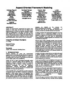
To solve the above issues we will propose a RecognizeStep stereotype extending SPEM Step metaclass and adding type : class [0..1] and placeOutsideSystem: Boolean [1] tag definitions:
Fig. 6 Recognize wizard step
• •
type – types of elements that will be created according added name. placeOutsideSystem – creates or not the elements outside of the system. If true, all the captured ele-
Fig. 7 The step Relate Use Cases and Actors in use case wizard
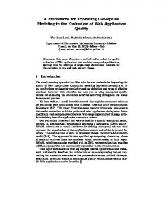
ments are placed on the same level as the system. If false, the elements are placed inside the system. In the Fig. 6 the recognize wizard step allows creating predefined element types according to the text parts. Different types of elements can be created and named according to the selected text. Recognizing is done by selecting a part of a plain text in the upper dialog part and from the right click menu choosing the element type which will be related with the recognized text part. After this the element with name and documentation is created in the table. The part of the text in the field is marked in a color relevant to the associated element type. The part of the text will be marked everywhere it appears. 3) Navigability and Reference From the presented case studies of the creation of use case and robustness analysis model, we can see the need of the suggestion of further actions and features after the accomplishment of the wizard. Not only the features should be suggested to the user, but also the model artifacts created with the help of the wizard should be reused. The features could be: other wizard, report generation, model transformation, matrices, validation suites, etc. In order to have the standard mechanism of reference we have extended the functionality of the hyperlink dialog. This allows accessing MagicDraw features using the standard hyperlink mechanism not only from the wizard but also from anywhere in MagicDraw. As MagicDraw hyperlinks can be added into a text, it allows describing the reference. The hyperlinks into each feature are defined by a different protocol which allows transferring the needed properties. For example, to generate a report, the report template name and model scope from which the report will be generated is described while creating the hyperlink. After clicking on such a hyperlink model report, the documentation is created without a need to go through the same reports generation steps. In the row “Suggest views and move to further steps” of the Tables 1 and 2 we can see the extended use of hyperlinks to report generation, validation and other features. D. MD Wizard Prototype Implementation in MagicDraw The prototype of the proposed approach was implemented as MagicDraw plug-in [4], which contains MD Wizard Profile customized with MagicDraw DSL Engine and a wizard generation cartridge implemented using MagicDraw Open API [24]. The plug-in generates wizards that guide through the process of model creation according to the modeled workflow, see Fig. 7 and Fig. 8 for sample screen shots demonstrating the execution of the presented wizard models. V. CONCLUSIONS AND FUTURE WORK In this paper we have presented MD Wizard – a novel model-driven framework for defining wizard-based guidance for custom modeling methods in UML modeling tools. The framework is composed of the following parts: • SPEM 2.0 UML profile for modeling workflows;
Fig. 8 The step Capture Entity Classes in robustness analysis wizard
DARIUS SILINGAS ET. AL.: MD WIZARD – A MODEL-DRIVEN FRAMEWORK FOR WIZARD-BASED MODELING GUIDANCE IN UML TOOLS 615
MD Wizard profile for enriching the SPEM 2.0 based workflow models with wizard-related details; • UML tool-specific cartridge for generating wizards from the user models based on MD Wizard profile. The impact of the proposed MD Wizard on the domain of software modeling and development is multifold: • The new model-driven profile and formal method for SPEM workflow extension present all needed information for execution of wizards supporting custom modeling methods. • The customization makes the method suitable not only for execution of straightforward workflows, but also extendable for advantage methodologies supporting incremental and iterative development. • Approach provides automation not only to accomplishing actions, but also to gathering data according modeling language rules. In the future, we plan to refine MD Wizard profile to support more specific modeling tasks and provide the Open API for customizing and extending the wizard generation cartridge for specific needs1. •
ACKNOWLEDGMENT The authors would like to thank No Magic, Inc, especially the MagicDraw product team for comprehensive support. REFERENCES [1]
I. Jacobson, G. Booch, J. Rumbaugh, Unified Software Development Process, Addison Wesley, 1999, ISBN 0-2015-7169-2. [2] D. Rosenberg, M. Stephens, M. Collins-Cope, Agile Development with ICONIX Process, Apress, 2005, ISBN 1590594649. [3] Object Management Group (OMG), Software & Systems Process Engineering Meta-Model Specification 2.0, 2008, OMG Document Number: formal/2008-04-01. [4] No Magic, Inc. MD Wizard plug-in, http://www.magicdraw.com/ main.php?ts=navig&cmd_show=1&menu=methodology_wizards [5] J. Bezivin, In search of a basic principle for model driven engineering. CEPIS, UPGRADE, The European Journal for the Informatics Professional, V(2) :21–24, 2002. [6] Meta Object Facility (MOF) 1.4 Specification. OMG, Inc. Final Adopted Specification. [7] J. Miller and J. Mukerji, Model Driven Architecture 1.0.1 Guide, OMG, Inc 2003. [8] D.K.C. Chan and K.R.P.H. Leung, Software Development as a Workflow Process, Proceedings of ICSC, Hong Kong, China, pp. 282-291, December 1997. [9] S. Balsamo and M. Marzolla, Simulation modeling of UML software architectures, the 17th European Simulation Multiconference, Nottingham, UK, pp. 562-567, June 2003. [10] A. Barnes and J. Gray, COTS Workflow and Software Process Management: An Exploration of Software Engineering Tool Development, Australian Software Engineering Conference, Queensland, Australia, pp. 221-234, April 2000.
1 The work is partially supported by Lithuanian State Science and Studies Foundation according to High Technology Development Program Project "VeTIS" (Reg.No. B-07042)
[11] L. Fuentes, J. Manrique, P. Sánchez, Execution and simulation of (profiled) UML models using pópulo, Proceedings of the 2008 international workshop on Models in software engineering, Leipzig, Germany, pp. 75-81, May 10-11, 2008, ISBN:978-1-60558-025-8. [12] B. Combemale, X. Crégut, A. Caplain, and B. Coulette, Towards a rigorous process modeling with SPEM, 8th International Conference on Enterprise Information Systems: Databases and Information Systems Integration, ICEIS 2006, Paphos, Cyprus, pp. 530-533, May 23-27, 2006. [13] R. Bendraou, B. Combemale, X. Crégut. and M.P. Gervais, Definition of an Executable SPEM2.0, In Proceedings of the 14th Asia-Pacific Software Engineering Conference (APSEC), IEEE Computer Society press, Nagoya, Japan, 2007. [14] N. Debnath, D. Riesco, G. Montejano, D. Romero, M. Uva, MP. Cota, et al, Supporting the SPEM with a UML Extended Workflow Metamodel, ACS/IEEE International Conference on Computer Systems and Applications (AICCSA'06), Dubai/Sharjah, pp. 1151-1154, March 811, 2006. [15] Y. Feng, L. Mingshu, W. Zhigang, SPEM2XPDL: Towards SPEM Model Enactment, Front. Comput. Sci. China, Higher Education Press, co-published with Springer-Verlag GmbH, pp. 1-11, March 28, 2008. [16] J. Smith, D. Popescu, A. Bencomo, IBM Rational Process Advisor: Integrating the software development process with IBM Rational developer and tester v7 tools, IBM report, 12 Dec 2006. [17] P. Kroll, Introducing IBM Rational Method Composer, The Rational Edge, 15 Nov 2005 [18] Eclipse Process Framework Project, http://www.eclipse.org/epf/ [19] Ivar Jacobson International, WayPointer, http://www.ivarjacobson. com/products/waypointer.cfm [20] TechnoSolutions Corporation, Visual Use Case, http://www. visualusecase.com/ [21] Cheat sheets in Eclipse, http://www-128.ibm.com/developerworks/ library/os-ecl-cheatsheets [22] J. Zhou and T. Stålhane, A Framework for Early Robustness Assessment, Software Engineering and Applications (SEA’ 04), MIT Cambridge, MA, USA, 64-69, 2004. [23] A. Cockburn, Using Both Incremental and Iterative Development, STSC CrossTalk (USAF Software Technology Support Center) 21 (5): pp.27– 30, 2008, ISSN d0000089. [24] No Magic, Inc, MagicDraw OpenAPI, http://www.magicdraw.com/ main.php?ts=navig&cmd_show=1&menu=download_manualpenapi