applications including process planning systems for ma- chining and assembly, and ... Several issues in developing modular, component- based CAPP systems ...
IIE Transactions (1998) 30, 893±903
A modular architecture for rapid development of CAPP systems for agile manufacturing SHAW C. FENG1 and CHUN (CHUCK) ZHANG2� 1
Manufacturing Systems Integration Division, Manufacturing Engineering Laboratory, Metrology Building A-127, National Institute of Standards and Technology, Gaithersburg, MD 20899, USA 2 Department of Industrial Engineering, FAMU-FSU College of Engineering, 2525 Pottsdamer Street, Tallahassee, FL 32310, USA
Current manufacturing planning software systems, such as computer aided process planning (CAPP) systems, are general and in a closed form. It is very dicult to modify these systems to respond to a user's dynamically changing needs. These systems are no longer suitable for agile manufacturing. This paper presents research aimed at developing a novel architecture for the rapid development of CAPP systems. The architecture supports the construction of CAPP systems from prepackaged, plug-compatible software components. Speci®cations of the architecture and its building blocks are de®ned. Several important issues in architecture implementation are discussed, and an experimental system is illustrated. Finally, an Internet-based distributed CAPP system architecture is presented as a preview of next generation CAPP system development.
1. Introduction Global competition is putting severe pressure on pro®t margins and driving manufacturers to deploy new ways of doing business. Therefore manufacturing industry needs to adopt more eective and ecient production strategies to meet the challenges of a shorter life-cycle, higher quality, lower cost, and a wider variety of customer demands. This increased emphasis on achieving highly adaptive manufacturing to reduce manufacturing costs and to better utilize manufacturing capacity has led to a critical focus on agile manufacturing to achieve these goals. An agile enterprise could swiftly recon®gure operations, processes, and business relationships, thriving in an environment of continuous and unpredictable change. Manufacturing software systems play a key role in the implementation of agile manufacturing. However, current software systems are monolithic. They are general and in a closed form. The problems associated with these systems are as follows: limited extensibility, limited functionality, low level of integration with other applications, and high development and maintenance cost. Modifying these systems to suit a user's dynamic needs is dicult. In today's manufacturing industry, most production projects are dynamic and mission-oriented in nature. Traditional software development techniques do not cope well with the needs of open systems, and in �
Corresponding Author
0740-817X
Ó
1998 ``IIE''
particular, with rapidly changing requirements which are crucial for agile manufacturing. In addition, current Computer-Aided Process Planning (CAPP) systems are not interoperable with other related systems such as those for Computer-Aided Design (CAD), scheduling and production planning. CAPP is considered a crucial link between CAD and Computer-Aided Manufacturing (CAM) (e.g., production/scheduling systems). Over 30 years of research into CAPP has resulted in a wealth of knowledge. As a result, many experimental and commercial CAPP systems have been developed. This research eort has been concentrated on the following subjects: general CAPP methodology (both variant and generative), AI approaches to process planning, system development for various types of applications including process planning systems for machining and assembly, and methodologies for performing individual sub-tasks in process planning, such as feature extraction and machining tolerance balancing. Most researchers have focused on a particular aspect of process planning, with only a few addressing the issue of systems integration infrastructure. Integration barriers, along with other obstacles in CAPP research, inevitably resulted in the unsuccessful practical implementation of CAPP [1]. Like general manufacturing planning software systems, the traditional CAPP systems can no longer meet the requirements of modern manufacturing with constantly changing products and resources. Existing CAPP systems are generally closed form and limited to a speci®c type of products. In addition, building a new CAPP system en-
894 tails constructing new knowledge bases. An alternative would be to assemble reusable software components with system developers only creating the specialized knowledge for reasoners new to speci®c tasks. On the other hand, advancement in software engineering allows component-based software architectures to be realized [2]. In this study, a novel architecture is proposed for rapid development of CAPP systems for agile manufacturing. Several issues in developing modular, componentbased CAPP systems are discussed in the following sections.
2. Related works In the past two decades, a substantial number of studies have been reported on CAPP, ranging from works on narrowly focused optimization of speci®c parts of the manufacturing system (e.g., machining operations, group technology, and NC programming) to those with a strong emphasis on the optimization of the whole manufacturing system, including product design, production control and management. The early research was mainly focused on variant process planning systems [3,4]. The second generation of CAPP systems employed semi-generative and generative CAPP approaches [5,6]. Another branch of research concentrated on the application of knowledgebased systems and arti®cial intelligence techniques to process planning [7,8]. As mentioned earlier, these eorts were focused on particular aspects of process planning, with only a few addressing the issue of a uni®ed system architecture and the integration of sub-systems in process planning. The evolution, state-of-the-art, and future directions have been discussed in several review and survey papers [1,9±11]. Based on both these discussions and others, some key structural characteristics of future CAPP systems can be isolated. They include: · Be modular to incorporate new trends such as generic, rapid, distributed and/or reactive planning; · Be transparent to facilitate the user's understanding of its structure, behavior and outcome; · Be extendible and adaptable to new applications, and facilitate the inclusion of new data bases and knowledge, as well as being customizable; and · Ensure a person is in the loop to participate in the decision making. In an eort to develop an integrated and ¯exible process planning system, Hetem et al. [12] proposed a process planning enabling platform. A layered software structure was developed and the planning modules were identi®ed. The speci®cations of the enabling platform for machining process planning systems were described. This research provided a gateway for the development of viable process planning systems.
Feng and Zhang Recent advances in computer science have led to the development of reusable, component-based modular software systems. Some concepts and software frameworks have been proposed and implemented with the technologies of the Internet, the STandard for the Exchange of Product Data (STEP) [13] and the Common Object Request Broker Architecture (CORBA) [14]. The bene®ts of the component-based, reusable technique include faster development and more robust software systems. Although there are a number of systems developed using this concept, they are mainly high level, general purpose software systems. Very little work has been conducted to develop component-based systems for manufacturing process planning.
3. A process planning integration framework A framework is a software architecture that de®nes an open environment for the development and integration of application software components or systems in a given context. A process planning integration framework provides an environment for process planning functions to be readily integrated with each other and with product life cycle functions, such as product design or production scheduling. The following sections discuss the generic process planning system concept and an architecture, which provides a foundation for the framework. 3.1. Characteristics of the process planning function Process planning is a complicated task, which can be characterized as follows: · The process planning task varies from company to company and from product to product. The process planning task varies for dierent domains. With reference to Hetem et al. [12], we classify the process planning systems with the following speci®cation parameters: product domain, process domain, activity domain, planning method domain, input mode, and output resolution. These parameters are discussed in detail in Section 3.2; · The process planning function can be decomposed into a set of tasks that are relatively independent of each other. The ¯ow of data between the tasks results in the tasks interacting. The decomposition of process planning can be represented by IDEF0 diagrams that are discussed in Section 3.3; · The process planning function evolves as new processes and resources are available. The process planning task is dynamic in nature because the planning strategies and data involved change as new materials, processes and equipment are introduced.
A modular architecture for rapid development of CAPP systems for agile manufacturing
895
3.2. Speci®cations of process planning systems In general, process planning systems can be speci®ed by six domains: (1) Product domain In manufacturing industries, there are a wide variety of product types, geometries, materials, etc. A process planning system often only deals with a speci®c type of product, geometry or material. For instance, there are individual process planning systems for rotational and prismatic parts. (2) Process domain A process planning system is usually associated with a set of processes and technologies. For instance, there are individual process planning systems for machining, assembly and sheet metal processing. (3) Activity domain The activity domain characterizes the activities, such as degree of automation, size of production facility involved, etc. (4) Planning method domain Several dierent planning methods are used in process planning, such as variant, semi-generative, generative and arti®cial intelligence. (5) Input mode Depending on the applications and level of automation, several input modes exist in CAPP. They include manual input, GT code, special part description language, CAD generated data, and standard neutral data ®le (such as a STEP Part 21 ®le [15]). (6) Output resolution Output resolution refers to the level of detail in the generated process plan. The generated process plan can range from a rough process routing sheet to a very detailed process plan with operation/machining step descriptions and parameters. For a process planning system, the system requirements can be de®ned by these domain speci®cations.
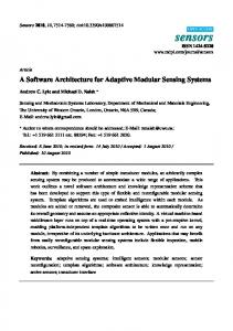
Fig. 1. Decomposition of the process planning function.
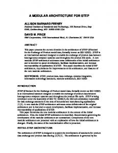
process sequences'' can be decomposed into four subtasks as is shown in Fig. 2. 3.4. Component-based CAPP system architecture Based on the preceding analysis, it can be concluded that the current structure of CAPP systems is no longer suitable for today's dynamic manufacturing environment and a new system architecture is needed. In this study, a novel integration framework is proposed for the rapid development of CAPP systems for agile manufacturing. This architecture is built upon the component-based software system concept. The architecture includes: the activity model (see Section 3.3), the data model (see Section 3.4.3), the software component library (see Section 3.4.2), the user requirements and software component functions mapping algorithm (see Section 3.4.1), the user interface with a scripting capability (see Section 4), the component composition mechanism (see Section 3.4.3), and the resource database. Figure 3 depicts the general architecture of the component-based CAPP system environment. The key issues of the architecture are discussed in the following three sections.
3.3. The process planning function and its decomposition Process planning involves many complicated tasks. Different application domains can have dierent functional requirements for process planning. In general, the process planning function involves the following tasks: (1) process sequence planning; (2) operation planning; (3) shop ¯oor routing planning; (4) generate control programs; and (5) validate plans and programs. The links between these sub-tasks are the data and controls. The decomposition of the process planning function can be described by activity models. Figure 1 shows an activity model (in an IDEF0 diagram [16]) which describes the typical tasks involved in a process planning function and their links. Some of the tasks can be further decomposed into various sub-tasks. For instance, the task ``generate
Fig. 2. Decomposition of the task ``generate process sequences''.
896
Feng and Zhang ledge-based approach for system requirements and software component functions matching. De®nition of the software component ¯ow
Fig. 3. General framework of component-based CAPP systems.
As discussed previously, a visual scripting approach is used to implement the framework. A script is a set of software components with compatibly connected input and output ports. The input/output ports de®ned for a set of components and the rules that determine plug-compatibility constitute a scripting model [17]. A CAPP system is generated from a scripting model. Scripting models vary depending on system requirements. In a scripting model, branching and junction are possible in addition to single ¯ow. One bene®t of the ¯ow-based component composition is that new functionality can be added or removed by simple modi®cations to the scripting model. Figure 4(a) shows a general scripting model for a typical process planning system, while Fig. 4(b) shows a detailed version of the scripting model for the system. Inputs/outputs compatibility checking
3.4.1. Framework The framework for the component-based CAPP system integration includes the control mechanism to construct CAPP systems from prepackaged, plug-compatible software components. The framework supports the selection of software components, the de®nition of the software component ¯ow, compatibility checking of inputs/outputs of adjacent components, and the execution of software components or composed systems. In this study, the framework is implemented using a visual scripting approach [17]. Visual scripting supports the interactive construction of CAPP systems from software components by direct manipulation and graphical editing.
The framework has the capability of checking the compatibility of input/output ports between adjacent software components. When the compatibility is not satis®ed between the output ports of the ®rst component and the input ports of the second component, the framework will provide a warning message and these two components will not be linked. The user can check the input/output
Selection of software components There are two ways for software components selection: manual and automatic. In the manual software component selection, for each task the user chooses a component from the library based on the system requirements. For instance, if a rotational machined part is the subject for process planning then the software components for rotational machined parts will be selected for all the needed tasks. It should be noted that sometimes the user can skip the component selection for some tasks, if they are not necessary. For example, if control programs (e.g., NC and robot programs) are not needed in a process planning job, the user can skip component selection for task 4 (``generate control programs'') and task 5 (``validate control programs''). In our prototype system, the framework only supports the manual selection of software components. Future research will be directed to the automatic software component selection with a know-
Fig. 4. Scripting model for a typical process planning system.
A modular architecture for rapid development of CAPP systems for agile manufacturing requirements of a speci®c component once the component is selected. Execution of components or the system After all the components are selected and linked, a CAPP system is developed. The user can execute the system by running the scripting model, and the system will generate the output (process plan) with the given product data. Since process planning is a complicated manufacturing planning task, it is almost impossible to obtain an optimal process plan at the ®rst attempt. It may be iterative, and human interaction is necessary in most cases. In this study, the framework provides a run-time mode in addition to the execution of the entire scripting model. In the run-time mode, a software component provides its outputs when all its input ports are connected. This runtime mode provides the user with the opportunity to look at the intermediate outputs of the software components. The user can change the outputs (e.g., tools or machine tools selected) as necessary. 3.4.2. Component library The component library includes a set of software components for process planning tasks. In this study, software components for ®ve process planning tasks are speci®ed and developed. In each task, there are a few domain-speci®c software components. For example, the task ``generate process sequences'' might include the software components for generating process sequences for three dierent product/process domains: rotational machined parts, non-rotational machined parts and sheet metal parts. The software components within a category have the same input/output port speci®cations since they are to be connected to the same components in other categories with the same data interface. A software component is speci®ed by its functionality, data interface and resource requirements. It performs a speci®c task or tasks with the built-in algorithm when all its input ports and resource ports are connected. Listed below are the speci®cations of an example software component in the modular CAPP system development environment. Software component: Generate process sequence Functions: Select and sequence a set of manufacturing processes to make the part Input ports: · Product data · Tooling/material inventory · Process change requests Output ports: Draft Process Sequence Resource ports: · Material stock description · Standard process models · Machining resource description
897
The component-based system provides a new direction in manufacturing planning software development. The following possible way for the next generation of manufacturing software development is envisioned. Based on the system requirements, the system developer selects an appropriate framework for the system. Software components with a standard data interface can be either developed by company experts or by third-parties. These components can then be ``assembled'' together using the architecture to form the software system. 3.4.3. Glue mechanism for component composition Software components communicate by passing data and control from one component to the next through their input and output ports. After the software components are selected, they are to be ``glued'' together according to their functional relationships. The glue mechanism de®nes the following information between two software components: the logical compatibility, speci®cations of the input and output ports (discussed in Section 3.4.2), and the data objects of the input and output ports. Logical compatibility In this study, the logical compatibility de®nes the speci®cations of the plug requirements of a software component. It includes the compatible upstream and down stream components for an individual component and the connecting sequence requirements. Some components may have output ports which are connected to more than one components' input ports. Likewise, some components may need outputs from more than one component as inputs. In such cases, the compatibility speci®cations de®ne the plug-requirements. Using the scripting model shown in Fig. 4(b) as an example, the software component for ``generate process sequences'' is connected to two components ± ``generate operations'' and ``generate shop ¯oor routing'' while the component for ``generate control program'' requires the outputs from these two components as inputs. A software component will not operate properly unless all its required ports are connected to compatible ports of the related components and are receiving data. De®nition of data objects The de®nition of data objects is very important for the component-based CAPP architecture. In this study, the interdependence of data objects in the software components is de®ned in a data model using the EXPRESS modeling method, which is speci®cally developed for STEP and documented in ISO 10303-11 [18]. Figure 5 shows a portion of the product model referring to AP224 (application protocol for mechanical product de®nition for process planning using form features) [19]. It contains the information pertaining to the part shape, which can be represented by both the manufacturing feature and the
898
Feng and Zhang
Fig. 5. Product data model for the process planning function de®ned in AP224.
B-Rep method. The part shape is composed of a number of Shape aspect which is described with Property, Geometry tolerance, Brep and Shape element. This product data model de®nes the data for process sequence planning, operation planning and NC programming. Fig. 6 shows the data object structure in a process plan de®ned in AP213 (application protocol for numerical control (NC) process plans for machined parts) [20]. A process plan is composed of a series of operations, which can be classi®ed as Part loading, Machine setup, Material removal and Validation. Part object is the collection of all elements (Part object element) of a part that is of concern to a manufacturing operation. Figure 7 shows the related entities to Part object and Material removal.
4. Proving the concept ± an experimental system An experimental system was developed to prove the concept of the modular, component-based CAPP system. The system was developed in Visual BASIC which is an event-driven programming language developed by Microsoft Corporation, on a personal computer in the Microsoft Windows environment. When starting the system, the user is provided with a window to enable selection of the software components. The software component library is displayed at the bottom of the window. In a speci®c process planning task, the user can place the mouse-controlled cursor on an individual component and retrieve information about the component, i.e., the domains that the component supports will be displayed. The user can then select an appropriate component based on the domain requirements
Fig. 6. Data object structure in a process plan de®ned in AP213.
Fig. 7. Related entities to Part object and Material removal.
by clicking on that software component. In the current system, several commercial software modules and experimental software components developed by the authors are used as the building blocks for proving the concept. The commercial systems include: MetCAPP which is a CAPP software system developed by the Institute of Advanced Manufacturing Science, Inc, for process sequence generation and operation generation modules; MasterCAM which is an NC programming software system developed by CNC Software, Inc, Lathe Module and SmartCAM which is an NC programming software system developed by CAMAX Manufacturing Technologies, Inc, and Free Form Machining Module for control program (NC) generation modules. After all the software components are selected, the user can create the scripting model by linking the models in the desired sequence. The linking of components is done by selecting the ``Link'' function in the menu at the top of the window and clicking the two components to be linked. Before linking the components, the user can check the input/output requirements of a component by clicking the input/output buttons on the component in the scripting model. If the two components are incompatible, the components cannot be linked, and the system will display a warning message. Figure 8 shows an example of a complete scripting model. Once the scripting model is created, the user can execute either an individual software component (run-time mode) or the entire process planning system. In the runtime mode, a software component can be executed when all its input ports are connected. The user can edit the outputs when necessary. This run-time mode brings the user into the loop of the process planning function. In the run-time mode, the user executes a component and the system displays the output of this module. The user can edit the output and send it to the downstream modules. For the non-rotational part shown in Fig. 9, Figs. 10± 12 show the outputs of the ``Process Selection and Sequencing'' module, ``Operation Generation'' module and ``Control Program Generation'' module, whilst for the
A modular architecture for rapid development of CAPP systems for agile manufacturing
899
Fig. 10. Output of ``Process Selection and Sequencing'' module (non-rotational). Fig. 8. A complete scripting model.
rotational part shown in Fig. 13, Figs. 14 and 15 illustrate the outputs of the ``Process Selection and Sequencing'' module and the ``Control Program Generation'' module. Although this component-based CAPP system is an experimental system and only a few components exist in the software component library, the experience of the authors and other process planning practitioners is that this form of software development is very ¯exible and ®ts nicely to the dynamic system requirements commonly encountered in today's manufacturing environment. The software component-based software has many advantages over the traditional approach in developing large, monolithic software systems. These include: 1. It will greatly shorten the CAPP system design and development cycle. Development of a monolithic system can take years. However, once the software components are available, development of a componentbased CAPP system may only take days;
Fig. 9. An example part (non-rotational).
2. It allows system developers/users to focus on commercial applications integration rather than in-house development; 3. The system developer/user only needs to develop those functional modules that provide distinct advantage, rather than to repeat the development of available technology; 4. The system uses well de®ned interfaces which will reduce non-standard content and enable higher reuse of integrated components; 5. It enables a true computer-integrated manufacturing planning environment. In this experimental system, all software components reside in the same computer. It does not allow a process planning task performed with software components running on heterogeneous computer platforms distributed in various physical locations. However, in today's manufacturing industry, products are rarely designed, manufactured and maintained entirely by a single company. This requires participating companies to be organized in a collaborative virtual enterprise. The process planning function in a virtual enterprise oers many
Fig. 11. Output of ``Operation Generation'' module (non-rotational).
900
Fig. 12. Output of ``Control Program Generation'' module (non-rotational).
challenges ranging from design and manufacturing data management to knowledge sharing. In the next section, a novel component-based, distributed CAPP architecture is introduced to address these challenges.
5. Next generation process planning systems ± component-based, distributed CAPP systems Recent advances in computer technology, particularly the Internet, make it possible for geographically distributed manufacturers to acquire and share product data from each other and to run remotely located software. They provide an eective tool for achieving the distributed component-based CAPP systems. The authors envisage the following possible way to produce the next generation of CAPP software. Based on the product/process re-
Feng and Zhang
Fig. 14. Output of ``Process Selection and Sequencing'' module (rotational).
quirements, the system developer de®nes the system requirements and selects an appropriate framework. Then, he/she will search on the Internet for available software components. Once the components are found, the system developer navigates to the corresponding pages using a www browser and selects an appropriate component for each process planning task. Using the framework and the selected software components, a CAPP system can be constructed by ``assembling'' these components. The components are usually developed by specialized software vendors and charges will be applied to the CAPP developer/user once the service is requested. The following sections describe an architecture of a distributed component-based CAPP system built upon the Internet and product data and system interoperation standards±STEP and CORBA. The theory and practice of systems integration using CORBA can be found in Mowbray and Zahavi [21] and Hardwick et al. [22]. 5.1. Framework A framework provides an organized environment for running a collection of CAPP software components
Fig. 13. An example part (rotational).
Fig. 15. Output of ``Control Program Generation'' module (rotational).
A modular architecture for rapid development of CAPP systems for agile manufacturing (see Fig. 16). It de®nes the rules of engagement for ``wiring'' components together so that they can play in suites. In this new environment an individual component is like a hardware integrated circuit; the framework provides the board; and the object request broker (ORB) provides the backplane. The framework helps the user integrate software components. All the components have late and ¯exible binding and well-de®ned interfaces so that they can be implemented independently. A component exposes its interfaces to its clients via IDL and communicates with other objects using the ORB. The basic elements in the framework are described as follows: · The user interface oers a visual integration. It provides a framework for sharing and subdividing a display window so that dierent components can share the screen's visual real estate in a seamless way. The user interface facility also deals with scripting. Scripting languages use late-binding mechanisms±as opposed to binding at compile time±you can create and attach scripts ``on the ¯y'' to components; · The information management includes compound document storage and data interchange facilities. It also de®nes standards that components use to encode and represent their data, to de®ne and exchange metadata, and to model information; · The task management provides facilities for managing work¯ows, scripting and task automation. A task can be composed of a single operation or sequences of operations; · The system management facility includes interfaces and services for managing, con®guring, and operating distributed software components. For a distributed component to be managed, it must implement IDLde®ned management interfaces.
901
5.2. Information infrastructure Communicating information between dierent software tools or components is a problem common to many application domains. In manufacturing, the multifaceted nature of design information makes communications particularly dicult. An information infrastructure is needed to allow the process planning tasks to communicate eciently. Fig. 17 presents an information infrastructure for the distributed component-based CAPP systems. This infrastructure combines the Internet as software delivery vehicle with the STEP standard for data exchange and the CORBA standard for interoperation of the software components. Connected through this communication mechanism are a number of servers, repositories, and browsers. They belong to dierent planning domains and perform dierent process planning tasks. 5.3. An illustration of software component execution Figure 18 shows an example of information ¯ow through which the task ``process sequencing'' is performed. There are four steps in the execution of the software component for process sequencing:
Fig. 17. The information infrastructure for the distributed component-based CAPP systems.
Fig. 16. A framework of CORBA-based distributed CAPP system.
Fig. 18. Information ¯ow for task ``process sequencing''.
902 1. The user navigates to a page containing product model using the WWW browser and selects an icon for product model data and process model data; 2. The Web Server communicates with the Database Server and the user is asked if he/she wants to check this model out from the Database Server; 3. The checkout is validated and an identi®er for the model is sent to the Process Sequences Server; 4. The Process Sequencing Server requests the data needed to service the request from the Database Server and performs selection and sequencing of a set of processes to transform raw materials into ®nished parts.
6. Conclusions The framework of the component-based CAPP system provides a new concept for the development of the next generation of manufacturing planning software. This research has illustrated the basic structure of componentbased CAPP systems, and has de®ned the speci®cations of the architecture and its building blocks. The issues for implementing the architecture are discussed. Based on the speci®cations, an experimental system has been developed and implemented to prove the concept. The experience of the authors and other practitioners is that this new system architecture is superior to traditional systems for process planning in a dynamic manufacturing environment. In this study, an Internet-based distributed process planning system architecture has also been proposed and speci®ed as a preview of the next generation of manufacturing planning software architecture. This research may be extended by extending the concept to other manufacturing planning (e.g., scheduling, manufacturing resources planning, and manufacturing execution.), software development and the integration of these planning systems.
Acknowledgement This research has been partially supported by the National Science Foundation (Grant No. DMI-9510456). The authors would like to express their appreciation to the agency.
Disclaimer No approval or endorsement of any commercial product by the NIST is intended or implied. The work described was funded by the United States Government and is not subject to copyright.
Feng and Zhang References [1] El Maraghy, H.A. (1993) Evolution and future perspectives of CAPP. Annals of the CIRP, 42, 739±751. [2] Shaw, M., Deline, R., Klein, D.V., Ross, T.L., Young, D.M. and Zelesnik, G. (1995) Abstractions for software architecture and tools to support them. IEEE Transactions on Software Engineering, 21 (4), 314±330. [3] Tulko, J. (1981) Lockheed's GENPLAN, in Proceedings of 18th Numerical Control Society Annual Meeting and Technical Conference, Dallas, TX. Numerical Control Society, Glenview, IL. [4] Chang, T.C. and Wysk, R.A. (1981) Interfacing CAD/automated process planning. AIIE Transactions, 1, 17±26. [5] Iwata, K., Makino, Y., Oba, F. and Sugimura, N. (1979) Development of non-part family type computer aided production planning system CIMS/PRO, SME Technical Report, MS 79-15, pp. 1±6, Society of Manufacturing Engineers, Dearborn, MI. [6] Eversheim, W. and Cobanoglu, M.T. (1989) Integrated process planning and part programming system for machining forging dies, in Proceedings of CIRP International Workshop on CAPP, pp. 37±53, College Park, PA. [7] Nau, D.S. and Chang, T.C. (1983) Prospects for process selection using arti®cial intelligence. Computers in Industry, 9, 253±263. [8] Chu, C.H. and Wang, H.P. (1988) The use of arti®cial intelligence in automated process planning. International Journal of Operations and Production Management, 8, 5±18. [9] Ham, I. and Lu, S.C-Y, (1988) Computer-aided process planning: the present and the future. CIRP Annals, 37, 47±59. [10] Alting, L. and Zhang, H. (1989) Computer-aided process planning: a survey of a decade. International Journal of Production Research, 27, 553±585. [11] Eversheim, W. and Schneewind, J. (1993) Computer-aided process planning: state-of-the-art and future development. Robotics & Computer-Integrated Manufacturing, 10, 65±70. [12] Hetem, V., Carr, K., Lucenti, M., Ruiz, X., Zhu, X., Ferreira, P. M. and Lu, S. C.-Y. (1995) Speci®cation for a process planning enabling platform. Journal of Systems Engineering, 5, 48±59. [13] ISO Standard 10303 Part 1: Overview and Fundamental Principles, (1994) International Organization for Standardization, Geneva, Switzerland. [14] The Common Object Request Broker Architecture: Architecture and Speci®cation, Version 2.0, (1996) Object Management Group. [15] ISO Standard 10303 Part 21: Implementation Methods: Clear Text Encoding of the Exchange Structure, (1994) International Organization for Standardization, Geneva, Switzerland. [16] Feng, S. (1996) A machining process planning activity model for systems integration. NIST Interagency Report, NISTIR 5808, The National Institute of Standards and Technology, Gaithersburg, MD. [17] Nierstrasz, O., Gibbs, S. and Tsichritzis, D. (1992) Componentoriented software development. Communications of the ACM, 35, 160±165. [18] ISO Standard 10303 Part 11: EXPRESS Language Reference Manual, (1994) International Organization for Standardization, Geneva, Switzerland. [19] ISO Standard 10303 AP 224: Mechanical Product De®nition for Process Planning Using Machining Features, (1994) International Organization for Standardization, Geneva, Switzerland. [20] ISO FDIS 10303 AP 213: NC Process Plans for Machined Parts, (1997) International Organization for Standardization, Geneva, Switzerland. [21] Mowbray, T.J. and Zahavi, R. (1995) The Essential CORBA: System Integration Using Distributed Objects, Object Management Group, Framingham, MA.
A modular architecture for rapid development of CAPP systems for agile manufacturing [22] Hardwick, M., Spooner, D., Rando, T. and Morris, K.C. (1996) Sharing manufacturing information in virtual enterprises. Communications of the ACM, 39(2), 46±54.
Biographies Dr. Shaw C. Feng is a Mechanical Engineer in the Manufacturing Systems Integration Division of the Manufacturing Engineering Laboratory at the National Institute of Standards and Technology (NIST). He received his Ph.D. and M.S. degrees in Mechanical Engineering from the University of Wisconsin-Madison in 1987 and 1984, respectively. Dr. Feng has extensive experience in developing CAD, CAM, and automated inspection software for computer integrated design and manufacturing. He has published numerous reports and papers in the areas of concurrent engineering, process planning, solid/surface mod-
903
eling, automated manufacturing systems, geometric tolerancing, and inspection planning. His current research areas include process planning and manufacturing software interoperability. Dr. Chuck Zhang is an Assistant Professor of Industrial Engineering at Florida A&M University-Florida State University College of Engineering where he teaches courses in computer-integrated manufacturing and industrial robotics. He received his Ph.D. degree in Industrial Engineering from the University of Iowa in 1993. Dr. Zhang's current research interests include tolerancing and metrology for precision machining, integration of manufacturing execution systems, and composite materials processing. He has published over 50 technical articles. His research projects have been with a number of organizations including NSF, NIST, DARPA, SME, Cummins Engine, Lockheed Martin and SPARTA. He was a guest scientist at the National Institute of Standards and Technology in 1995.