dedicated process-oriented and time-dependent sequential control were combined via automation networks. Finally, servers and workstations hosting, ...
A Modular Architecture for Building Automation Systems Wolfgang Granzer, Wolfgang Kastner, Georg Neugschwandtner and Fritz Praus Vienna University of Technology, Inst. of Computer Aided Automation, Automation Systems Group Treitlstraße 1-3, A-1040 Vienna, Austria {wgranzer, k, gn, fpraus}@auto.tuwien.ac.at
Abstract The deployment of building automation systems (BAS) allows to increase comfort, safety and security and to reduce operational cost. Today such systems typically follow a two-layered hierarchical approach. While control networks interconnect distributed sensors, actuators and controllers, a backbone provides the necessary infrastructure for management tasks hosted by configuration and management devices. In addition, devices interconnecting the control network with the backbone and the backbone with further networks (e.g., the Internet) play a strategic role. All BAS devices contributing to a particular functionality differ in their requirements for hardware. This paper discusses requirements for devices used in the building automation domain and presents our work in progress to assemble platforms with different purposes relying on a modular architecture.
1
ality than ordinary ones.1 Second, information technology (IT) and its infrastructure became accepted not only at the management level, but also at the automation level. This is due to the fact that functions of the former automation level can be realised with cheap IT hardware since environmental conditions in the building automation domain are not that harsh compared to industrial automation. Consequently, functions of the former automation level are split being reassigned either to field devices (e.g., implementing controller functionality) or management devices (e.g., realising process data monitoring). Management devices
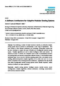
Backbone level Control level Intelligent field devices
1-4244-0379-0/06/$20.00 ©2006 IEEE.
Interconnection devices Control networks
Figure 1. Two-level architecture for BAS
Introduction
In [1] a standard model for all kinds of Building Automation Systems (BAS) is described. In this model, the system functionality is divided into three levels which are ordered hierarchically. At the field level, environmental data are measured and parameters of the environment are physically controlled. Automatic control is performed at the automation level whereas global configuration and managements tasks are realised at the management level. For years, the levels of the functional model have been mapped to separate networks when BAS had to be implemented. Sensors and actuators were interconnected via field networks. Controllers (e.g., DDCs) responsible for dedicated process-oriented and time-dependent sequential control were combined via automation networks. Finally, servers and workstations hosting, for instance, applications for trend logging and visualisation were linked by a management network. Of course, vertical access for data exchange from the lowest to the highest level had to be provided. Nowadays, the standard three level functional hierarchy model can be implemented as a flatter, two-level architecture (Fig. 1) [2]. This is for two reasons. First, so called intelligent field devices incorporate more function-
WAN
Backbone network
As a result, the two-level architecture consists of a control network level and a common backbone which together form the building automation network (BAN). The control network is home to field devices and has a typical bandwidth in the order of a few KBits/s. Since the requirements of management devices still cannot be fulfilled by this control network (e.g., a global consistent view of the entire system needs higher data rates), control networks are interconnected via a high-bandwidth (typically MBits/s) backbone network. At the intersection point between the networks, interconnection devices are used.
2
Device classes
Based on this novel view on a BAN, BAS devices and their functionality have to be re-classified. Sensor, Actuators and Controllers (SAC) are located at the control level. Representatives of this device class interact directly with the physical environment and are responsible for data acquisition and for controlling the behaviour of the environment. Additionally, they may include controller functionality. 1 For the rest of this paper, the term field devices is used as a synonym for intelligent field devices.
Interconnection Devices (ICD) link different networks and network segments together. Representatives of this device class enable BAS devices to interact either using the same network protocol (e.g., BAN to BAN) or via different protocols (e.g., BAN to IP). ICDs operate at different layers of the OSI Reference Model [3]. To extend the maximum physical network cable length, repeaters and bridges can be used acting at the physical and data link layer, respectively. While a router operates on protocols at the network layer, a gateway ensures transparency to applications that run on top of the protocol stack. For this reason, a gateway may be referred to as a protocol converter. A special form of interconnection is called tunneling. Using a tunneling protocol, whole packets of one protocol are wrapped into packets of another protocol. These encapsulated packets are transmitted through a so called logical tunnel to another ICD where the packets are unwrapped. Depending on the layer the packets are encapsulated in, different names are used for tunneling devices. If tunneling is performed at the network layer, devices are called tunneling routers. As an example, a representative of a tunneling router-ICD could provide the encapsulation of IPv6 packets into IPv4 packets. Tunneling gateways on the other hand operate at the application layer. For example, a tunneling gateway-ICD could perform the tunneling of HTTP requests through Secure Sockets Layer. Finally, Configuration and Management Devices (CMD) are used to configure and maintain a BAS. Typical CMDs implement tasks including the change of control parameters, setting up of new automation tasks as well as monitoring, logging and archiving of process data values. In most cases, representatives of the CMD class will be located at the backbone level. Still, some representatives may be found at the control level (e.g., for on-site device configuration). Since CMDs are often controlled by humans, they provide some kind of (graphical) user interface (UI). Concerning the characteristics of the UI, CMDs can be further classified: • CMDs with only rudimentary UIs for simple configuration tasks, • CMDs with embedded UIs, such as more advanced operator devices, • CMDs with an integrated web-server to provide data for another CMD, • CMDs with fully fledged (graphical) UIs, like panels, workstations and PCs. Of course this classification is not clear cut, since, for instance, a personal digital assistant (PDA) being used for some configuration task that is connected to a BAN via a so-called network adapter (e.g., a SAC providing a serial interface) could either be considered as a CMD with an embedded UI or a CMD with a fully fledged graphical UI. Nevertheless this first approach helps to quantify requirements for the hardware when devices are designed and realized, as will be shown in the following.
3
Requirements analysis
In order to develop a modular, flexible hardware architecture the different devices classes have to be analysed in detail with respect to the following demands on: • Resources: The required functionality of the device significantly influences the demands on processing power and memory. • Interfaces: Different interfaces are desirable. – Network interfaces are of course mandatory to integrate the device into a BAN. – Point-to-point interfaces to perform configuration tasks. – Process interfaces for data acquisition and interacting with the physical environment. – Human machine interfaces for user interaction. • Power consumption: If a device is driven by battery or by a common power supply (e.g., via link power), the power consumption should be as low as possible. • Environment: Since BAS shall be operable for many years, the used devices shall be insensitive to rough installation environments. • Costs: Devices shall be as cheap as possible to keep the BAS installation (and maintenance) costs small. 3.1 Requirements on SACs • Resources: As SACs have to perform more or less simple tasks, small and low cost 8 or 16 bit microcontroller unit (MCU) based solutions are sufficient. The memory requirements are relaxed since the amount of process data (in the order of bytes to a few KBytes) to handle can be assumed to be small. • Interfaces: In order to configure and maintain a SAC device (e.g., upload new firmware), a simple pointto-point interface (e.g., serial) has to be provided. To exchange process data, a network interface is required. Compared to industrial automation, the demands on the response time2 are more moderate but they nevertheless exist (e.g., in the order of a few ms; cf. [2]). Wireless networks are gaining importance in BAS. Therefore, such interfaces have to be taken into account, too. For SACs, a process interface for interaction with the physical environment is also needed. • Power consumption: SACs are often supplied via link power to avoid the need for an additional power cable. In some cases, SACs may be even driven by a battery (e.g., glass break sensors). Here, low power consumption is of major concern. • Environment: As SACs are usually located in the field, they have to be robust and small. 3.2 Requirements on ICDs • Resources: Compared to SAC devices, the requirements on ICDs are quite similar. Since routing is not 2 The term response time is referred to as the time interval between action initiation (e.g., pressing light switch) and action execution (e.g., light on).
Table 1. Demands on BAS devices SAC Processing power Memory Response time Power consumption Physical size + : high
ICD
− o − (KBytes) o + +/−3 + o + + o : moderate − : low
4
Modular Hardware Architecture
CMD + + (MBytes) − − −
a very complex task, MCUs are sufficient to fulfill the processing power requirements of ICDs. However, routers and gateways may need additional memory for storing routing tables or caching data. • Interfaces: To configure and manage ICDs, some sort of local interface (e.g., EIA232, USB) is required. The main objective of ICDs is the interconnection of two or more network segments or networks. Therefore, ICDs need at least two (possibly different) network interfaces. • Power consumption: Since battery driven ICDs are uncommon, low power consumption is not as important as it is for SACs. • Environment: Interconnection devices will normally be located at central points in the building (e.g., in a switch cabinet). However, it is still important that ICDs are small and maintenance-free.
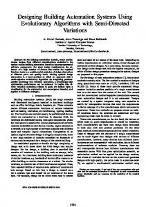
Gateway N-IF 1 N-IF 2 MCU Point-to-Point IF
MCU based CMD Network Interface
PC based CMD Network Interface
MCU
PC
HMI
HMI
Storage
Point-to-Point IF
IF
3 When ICDs are used for management access only, response time is less of a concern than when they are used for routing process data.
SAC Network Interface MCU
Process
3.3 Requirements on CMDs • Resources: Compared to SACs and ICDs, the performance and memory demands on CMDs are even higher. CMDs have to operate with data from the whole BAS and therefore are supposed to process higher data volumes (in the order of KBytes to MBytes). Additionally, management tasks require more processing power and (persistent) storage for software and data. • Interfaces: To be able to fulfill configuration and management tasks, a connection to the BAN is mandatory. Such an interconnection can be achieved using so-called network adapters (e.g., SAC with a serial connection). The demands on the response time can be seen more relaxed since management tasks are not time critical. Additionally, interfaces for varying UIs have to be provided. • Power consumption: Since server, workstation and PC-based CMDs are supplied via the power grid, power consumption is not of concern. • Environment: CMDs with fully fledged UIs will be normally located in mild environments (offices). Therefore, small size and robustness against rough environmental conditions are less important. For other CMD representatives, relaxed environmental conditions can be expected as well.
The introduced device classes obviously need different hardware due to the discussed requirements. Nevertheless they may share the same hardware components if appropriate. Our goal is to develop a modular architecture consisting of different, exchangeable hardware blocks which are able to fulfill embedded control, interconnection as well as configuration and management tasks. The resulting devices/plattforms shall be • universally applicable to serve as a basis for further work in the scope of building automation (e.g., test platform for protocol extensions), • compact, embedded, robust and of course low cost, • flexible (i.e., configurable in hardware by use of jumpers and software, which is especially useful for SACs and ICDs) and extensible, • easy to use, and • powerful, meaning that enough processing power and memory shall be available to implement representatives up to CMDs. Fig. 2 shows, from an abstract point of view, the different hardware building blocks which have to be assembled to provide the functionality for each device class. By selecting the corresponding hardware blocks, SACs, ICDs or even MCU based CMDs can be implemented. Router N-IF 1 N-IF 2 MCU Point-to-Point IF N-IF: Network interface IF: Interface
Figure 2. BAS devices
5
First experiences
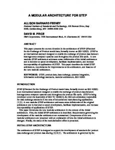
In the top section of Fig. 3, a mapping of the general model to a modular architecture intended for KNX/EIB [4] is shown. Beneath, possible implementations derived from this architecture are displayed. As a first proof of concept, different platforms have already been implemented following our modular architecture. On the one hand an integrated, compact and powerful platform named KNXcalibur was built. It is applicable in each of the mentioned device classes, but especially with ICDs and MCU based CMDs with an integrated webserver in mind [5]. On the other hand ”header boards” with modular components (power supply, point-to-point interface, process interface, network interface) and pin headers to connect different MCUs have been developed for building SACs. A wireless network interface for ICDs support will be available on a separate board. KNXcalibur is based on the Fujitsu 16 bit MB90330 family. A maximum operating frequency of 24 MHz, 4 UARTs, a 8/10 bit A/D converter and a SPI (Serial Peripheral Interface) as well as an external bus interface similar
MODULAR ARCHITECTURE Power
CPU Texas Instruments MSP430 Fujitsu MB90F334A Atmel AVR ATmega16
Network Interfaces
Ethernet
POSSIBLE IMPLEMENTATION
Power
Storage
USB
Ethernet
IP Gateway
TP-UART
USB
TP-UART
Power
MB90F334A
Ethernet
IP Tunneling Router
USB
TP-UART
USB
MB90F334A Power
MB90F334A
Wireless Router Zigbee
Router
Power
Power
Power
GUI
Storage
PC
Storage TP-UART/ Ethernet
I/O
HTTP
PC based CMD
MB90F334A
MCU based CMD
TP-UART/Zigbee MSP430 MB90F334A AVR ATmega16 EIA-232/PEI
SAC
TP-UART/ Ethernet
TP-UART
GUI
Zigbee
PEI/EMI
TP-UART
Process Interface and HMI
TP-UART
MB90F334A
Point-to-Point Interfaces EIA-232 USB
Storage SD Card Flash
Power
Figure 3. Hardware architecture for KNX/EIB to the ISA bus are provided. Moreover, USB functionality with device (USB 2.0 full speed) and mini host support is integrated into the controller. To support ultra low power SAC devices, a Texas Instruments 16 bit MSP430 MCU has been selected. It supports a maximum operating frequency of 8 MHz and serial communication interfaces, which can be operated as asynchronous UART or synchronous SPI interfaces. As an alternative MCU for SAC devices and an experimental platform for IDCs, the Atmel AVR ATmega16 is used. It is an 8 bit controller with a maximum operating frequency of 16 MHz. A mixed input voltage is required for all our components. The MB90330 and MSP430 run on 3.3 V whereas the ATmega16 needs 5 V. For USB support 5 V are required. Therefore, two low drop voltage regulators are used, which can be powered via an external mains adaptor, via the USB or via the KNX/EIB network using link power (only small loads up to 10 mA can be driven in the latter case). To support persistent storage of large amounts of data on KNXcalibur without requiring writing to the MCU onchip flash memory and to extend the latter, a SD/MMC card connection has been integrated. The SD/MMC card is accessed via SPI. For the MSP430 and AVR ATmega16 no further memory is required, since they are intended to serve in SAC devices. Simple buttons and LEDs are used as process inter-
faces. Moreover, a PEI connector, which offers digital and analog access to external sensors and actuators, is present in all cases. Serial connection to the PC side has been realised using EIA-232. True level converters (MAX232) and SUB-D connectors are placed. On KNXcalibur an USB connection has been implemented using the on-chip USB hardware. USB-B (USB device) and USB-A (mini host) connectors are present. To connect KNXcalibur to Ethernet, the Cirrus Logic CS8900A Ethernet LAN controller has been selected for use on the platform. It is a single chip, low-cost controller for embedded applications, which supports 10 MBit/s link speed and is accessed via an ISA bus interface. To support wireless connections a Chipcon CC2420 ZigBee module is used. It is a true single-chip 2.4 GHz IEEE 802.15.4 compliant RF transceiver with baseband modem and MAC support. 250 KBits/s effective data rate are possible. The CC2420 is accessed via SPI. Connection to KNX/EIB is realised in all cases with the Siemens TP-UART IC providing layer 1 and layer 2 access. It is the easiest, most flexible and cheapest possibility for accessing the KNX/EIB twisted pair medium. Optocouplers are used for galvanic isolation.
6
Conclusion
Due to the modular design concept, our hardware architecture is not limited to the use in a predefined application area. The design of a central component (KNXcalibur) is already finished. A low power platform based on the MSP 430 is currently under development. Moreover, interfaces to other BANs like BACnet [6] or LonWorks [7] are under investigation. In addition to this hardware architecture, an approach to modular software has to be developed to enable Hardware/Software Co-Design. Moreover, tools supporting appropriate configuration and management will be necessary.
References [1] “Building Automation and Control Systems (BACS) – Part 2: Hardware”, IS0 16484-2, 2004. [2] W. Kastner, G. Neugschwandtner, S. Soucek, and H. M. Newman, “Communication Systems for Building Automation and Control”, Proceedings of the IEEE, vol. 93, no. 6, pp. 1178–1203, June 2005. [3] “Information technology – Open Systems Interconnection – Basic Reference Model: The Basic Model”, ISO/IEC 74981, 1994. [4] “KNX Specification”, Konnex Association, 2004. [5] F. Praus, “A versatile networked embedded platform for KNX/EIB”, Master’s thesis, TU Vienna, 2005. [6] “BACnet – A Data Communication Protocol for Building Automation and Control Networks”, ANSI/ASHRAE 135, 2004. [7] “Control Network Protocol Specification”, ANSI/EIA/CEA 709.1, 1999.