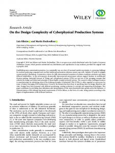
ECU Architecture. Concurrent Development. CPS. Plant Architecture. Control Application. Architecture. CPS. Separation of Concerns - Multiple decomposition.
Architecture Driven Development for Cyber-Physical Systems Gopal Raghav, Swaminathan Gopalswamy -Emmeskay Inc -www.emmeskay.com
Introduction Cyber Physical System (CPS) y Systems
consisting of computational and physical systems y Tight coordination between the two
Behavioral model-based development (MBD) approach y Address
development of individual systems y Inadequate for analyzing large scale system of systems
Architecture driven development (ADD) approach y Facilitates
development of large scale CPS
Focus of this presentation
Evolution of Embedded Systems Cyber Systems
Cyber Physical Systems (CPS)
Modern CPS
Traditional / Structured S/W Development
Logic
Hybrid (Continuous + Logic)
System of Systems Development Process Complexity
Analyze Behavior - Model Based Development
Ability to analyze before details are available Ability to manage variants -Architecture Driven Development (ADD)
What Next? Major challenges to development of CPS An architecture driven approach to development of CPS Enabling technologies Sample workflows illustrating the approach
Challenges to Development of CPS Concurrent Development
System of Systems
CPS
Distributed Development
Variant Management
Interacting System of Systems Approach 1 Use MBD to analyze individual CPS Integrate CPS into larger system Problem Leads to integration challenges Communication issues detected late
Need to understand performance of the system of systems Approach 2 Apply MBD to system of systems Involves details of all interacting CPS Problem Leads to scalability issues •Difficult to apply MBD techniques to large scale systems •Difficult to interpret results
Flap Limiter Elevator Load Feel
Altitude Alert
Auto-Flight System
Wind Shear Protection Stall Warning
Automatic Ground Spoilers Flight Director Automatic Throttle System Auto Pilot Auto Land
Auto Stabilizer Yaw Damper
Need to perform system analysis without involving details Solution: ADD
Variant Management Implementation Variants – Technology, Level of Detail Evolutionary Development Data Variants
Work products are continuously changing •Need for version control techniques •Need to address dependencies between work products V1
V2
V3
Need to manage the different dimensions of variants Apply select combinations to the CPS Solution: ADD
Distributed Development Globally Distributed Teams
Need to breakdown systems for distributed development
C1 System decomposition must be independent of component behavior Solution: ADD
Sys
C2
C3
Concurrent Development ECU 1
ECU 2
ECU 3
ECU Architecture Control Application Architecture
Plant Architecture
CPS
Separation of Concerns - Multiple decomposition Multiple views of the same system Need to reconcile views later Need to address integration issues Solution: ADD
Architecture as a Solution Our definition of architecture y
Topology of the system defining the hierarchy of subsystems, interfaces and connectivity between subsystems Interface
System Level Performance Impact Analysis Influence Range Analysis
Connectivity
Component
Facilitates Distributed Development
Architecture Driven Modeling Add rich metadata
X e _ Z e
A ltitu d e
Non-Functional analysis using architecture Description -Schedulability -Safety -Security -Latency
ta r g e t _ r a n g e
lo o k _ a n g le
t c _ t e s t in p u t s re s u lt s
missile guidance model
X e _ Z e ta r g e t _ r a n g e A l ti tu d e
lo o k _ a n g le
a lp h a
a lp h a fin _ c o m m
m
a n d
fi n _ c o m
m
a n d
a c h
m
a c h
a z _ m a z _ m g y r o
_ r a te q
c o n t r o lle r a ir fr a m
M is s ile
B o d y A n g u la r R a te
e
M is s ile
P o s itio n
M is s ile
A ltitu d e
Functional analysis using behavioral models
Architecture as a Solution Architecture provides the underpinning information System Decomposition -Independent of Component Behavior
Requirements Breakdown Specification Flowdown
Behavioral models, data, requirements and other properties can be associated with and managed using the architecture
Implementation Variants Data Variants
Evolutionary Variants - Versions
Constraints can be set to select combinations of the three variants
Architecture Views of Different “Concerns” Multiple, Valid, Architectural views exist Different views or perspectives are suited for different analysis/development purposes Need mapping between the views
Supplier1 Supplier 2
Plant
Control
ECU1
Team3
ECU2
Actuator Dynamics
Actuator Drivers Control Func2 Control Func3 Tasks at Rate 1
ECU3 Supplier 3
Physical System
Control Func1 Sensor Drivers
Team1 Team2
Sensor Dynamics
Tasks at Rate 3
Scheduler ISR Tasks at Rate 2
Multiple Views Application Architecture View
Embedded Architecture View Processor Process Thread
Snapshot from the tool IME
Application Software Component
Architecture Driven Approach Requirements and Goals Architecture - nodes can have variants
Safety, security, schedulability
Non-functional Requirements
RGA
Functional Requirements
SA V&V
System Architecture – nodes have variants
Behavior of the CPS
Architectural Views
Represent Verification and Validation Activities (V&VA)
V&V
Models generated are consistent with SA
Behavioral Models Multiple perspectives with mapping between them
Technological Requirements Architecture description methodology y y y y y
Need standardized descriptions of functional and embedded architectures Need to specify different components – functional, software, electronics, sensors and actuators Reconcile between architectural views while retaining their properties Need to specify variants Support incremental forms of analysis
SAE AADL (Architecture Analysis and Design Language)
Architecture driven modeling y y y y
Need to extract architectures from behavioral models and visualize them Need to migrate architecture descriptions into behavioral modeling domains such as Simulink Need to associate V&VAs with the underlying architecture and model variants Specify mapping and transition between multiple architectural views
IME (Integrated Modeling Environment) (Emmeskay, Inc)
Technology Description SAE AADL – SAE standard since 2004 8
y y
Tool neutral language to describe runtime architecture of embedded systems Model based analysis of embedded system architectures 8
y
www.aadl.info
Analysis of schedulability, safety, latency, etc
Several component categories for software and hardware - extensible 8 8
System, Process, Thread, Sub-program, Data, Processor, Bus, etc. Properties can be set on all components – built-in and user-defined
IME (Integrated Modeling Environment) – Commercial product 8
y y y
http://www.emmeskay.com/tools/ime
Architecture creation, extraction, analysis and visualization Model and variants management, tool neutral model manipulation, model parameterization Enterprise wide collaboration, version control, user authentication and access control
Illustrations – Architecture Driven Workflows
Generation of Functional Models OSATE
.aadl
.aaxl Import into IME
IME Configure Architecture Consistent Instantiation Tree Visualize Architecture Compose Model and Export from IME
Mine out Relevant Behavioral Models Simulink
Simulate and Author Behavioral Model
Generation of AADL models of Embedded System from Functional Models Simulink Behavioral Model
Set Attributes for each component Set the Processor, Process and Thread
View in different Perspective
AADL
Export
Multiple Views Application Architecture View
Embedded Architecture View Processor Process Thread
Application Software Component
Conclusions Architecture serves as the powerful underpinning Different aspects of CPS can be developed and integrated Architecture is the starting point for both functional and non-functional analyses Architecture facilitates management complexities posed by variants
Backup Slides
Goals Goals y Greater
target accuracy y Greater missile range y Work in all weather conditions y Weight and cost
System y Home
guidance system
8Semi-active
using radar detection
Missile Guidance System - SA System Targeting
Guidance Generate normal accel demands Acquire initial target position
Guidance Processor
M1
Limit Acceleration
Autopilot
(Seeker/Tracker)
Measure closing velocity between missile and target Estimate rate of change of slight line angle
Target Acquisition
Control accel normal to the body - generate fin commands
Tracker (Sightline Rate Estimator)
Calc Gains
M5
M2 M3
M4
Compute Command
M6