A Modular Robotic System with Applications to Space Exploration Matthew D. Hancher NASA Ames Research Center
[email protected]
Abstract Modular robotic systems offer potential advantages as versatile, fault-tolerant, cost-effective platforms for space exploration, but a sufficiently mature system is not yet available. We discuss the possible applications of such a system, and present prototype hardware intended as a step in the right direction. We also present elements of an automated design and optimization framework aimed at making modular robots easier to design and use, and discuss the results of applying the system to a gait optimization problem. Finally, we discuss the potential near-term applications of modular robotics to terrestrial robotics research.
1. Introduction Future space exploration missions will require autonomous robotic platforms that can be adapted to a variety of tasks, both autonomously and in cooperation with humans. A modular robotic architecture has the potential to offer a high degree of flexibility and faulttolerance at a low cost and mass. However, such architectures involve trade-offs that are currently poorly understood and have historically rendered modular robots inappropriate for use in a space mission setting. A modular robot is a robot built from components with standard electromechanical interfaces, making it possible to assemble the components in a variety of ways to suit a variety of purposes. The chief advantage of modular robotics to space missions arises from the ability to reuse hardware to perform multiple functions. In a sufficiently complex or open-ended mission this could result in a considerable savings in mass and hence also in cost. In addition fault-tolerance can be achieved with a small number of spare modules, requiring far less mass than would otherwise be needed for redundancy. A self-reconfiguring modular robot would even capable of self-repair. The modular robotics research community has focused primarily on the extreme case of robots made
Gregory S. Hornby University of California Santa Cruz
[email protected]
entirely from a single module type. While interesting to study, this form of modularity is not appropriate to the real-world needs of space robotics. A more practical modular robot would include a number of general-purpose and special-purpose module types, all designed with the anticipated range of mission tasks and configurations in mind. In this paper we outline a modular robotic system intended as one step in the right direction. We first summarize related work in modular robotics, and we discuss a number of potential applications for modular robotics to future space exploration missions. We then describe the design and manufacture of our initial prototype hardware. Next, we outline a simulation and design environment capable of automated morphology and controller design and optimization, and we present initial results of a quadrupedal gait optimization. Finally, we discuss the immediate application of this form of modular robotics to the laboratory and classroom setting as a low-cost generic platform for robotics research.
2. Related work Reconfigurable modular robots first emerged in the eighties in the context of manipulator arms [1]. The idea was popularized by the work of Mark Yim at Stanford in the early nineties, whose work extended the idea to fully autonomous robots including locomotion [2]. Since that time the modular robotics community has focused primarily on homogeneous robots, those constructed from many copies of a single module type. Existing modular robots can be divided into two categories according to whether the primary actuator is rotational or prismatic. Rotational modules are typically designed to be connected in chains, sometimes with branching, and are well-suited to armand snake-like behaviors and legged locomotion. The PARC/UPenn PolyBot robot [3], the Cornell Molecubes [4], and to some extent the Dartmouth/MIT
Molecule robot [5] fall into this category. Some rotational modular robots support self-reconfiguration, while others are manually reconfigured. By contrast, in prismatic modular robots the function and reconfiguration of the robot are tightly intertwined. Modules translate relative to each other, typically in a lattice-like structure, in order to achieve higher-level goals. For example, locomotion may be achieved by cyclically moving the rear modules to the front through a process of continuous reconfiguration. The Dartmouth/MIT Crystalline robot [6] and the PARC/UPenn Telecube robot [7] typify this category. A homogeneous design can introduce unnecessary complexity into robot and module designs. For example, rolling locomotion in a traditional rotational modular robot involves a long chain of modules connected in a tread-like topology [8], when in many situations it may be simpler to add wheel modules directly. Modular manipulator arms offering a range of rotational joint modules with different properties have been developed, such as the Rapidly Deployable Manipulator System at Carnegie Mellon [9]. These robots begin to flesh out the spectrum of modularity that lies between single-purpose custom-engineered hardware and pure homogeneous modularity. Unfortunately, no general-purpose heterogeneous modular architecture has yet been presented.
3. Modular robotics for space exploration Space exploration missions continue to place everincreasing demands on robotic systems [10]. For the limited missions of the next decade the traditional approach, using a small number of specialized robots whose capabilities span the range of mission requirements, will suffice. As we develop permanent robotic and human outposts in space and on the surface of the moon and Mars, however, the various advantages of modular robotic systems become more appealing [11]. In a human-robot collaborative mission the reconfiguration process could be facilitated by the astronauts, greatly simplifying robot design. For example, when assembling a large structure, astronauts could configure a robotic manipulator system as one large manipulator or as several smaller ones as desired for each phase of assembly. The same electromechanical interface could be used to install the end-effectors best suited to each subtask. In a purely robotic mission, a modular robotic system must be capable of reconfiguring itself. The approach taken in labs today, adding the capability for automatic connection and disconnection to each mod-
ule, is not the only option. For example, a specialized reconfiguration end-effector module could be included, thereby reducing the complexity of the remaining modules. Beyond simply reusing mass for multiple purposes, a modular robotic system has the additional advantage that it can be configured into entirely new forms to address unanticipated or changing mission needs. Its capabilities could be extended by launching additional modules at a later date as long-term mission needs evolve, which could then integrate seamlessly into the existing robotic community. The ability to easily remove and replace individual modules, either manually or in an automated fashion, could extend mission lifetimes. One important reason existing flight robots exhibit a highly centralized, monolithic design is the need to protect the control electronics within a thermally controlled environment. Robots exhibiting a high degree of modularity will depend on emerging technologies for electronics that can operate directly in extreme temperature and radiation environments.
3.1. In-space operations In-space operations include autonomous assembly, inspection, and maintenance and providing assistance to astronauts engaged in orbital extra-vehicular activity (EVA). These tasks involve moving about the structure and manipulating both small-scale connectors and instrumentation and large-scale components, which is time-consuming and dangerous [12]–[14]. The diversity of tasks at different scales typically requires human involvement or several different robots. Existing robotic arms, such as the Remote Manipulator System (RMS) [14], are good for moving large objects around the ISS but are too large for manipulating smaller ORUs for repair tasks, are hard to transport and position, and lack the ability to perform many construction tasks without aid. Humanoid robots, such as NASA’s Robonaut [15] and the Canadian Space Agency’s Dextre, are more capable for jobs involving smaller objects but are limited to tasks that are well-suited for a human, such as those that require no more than two arms. None of these robotic systems can be adjusted to handle tasks outside the range for which they were designed. A reconfigurable modular robotic system, on the other hand, would be able to form robotic structures at different scales and with different manipulation capabilities. Here the modules types might include a number of actuators with different specifications, branching
(a)
(b)
(c)
Fig. 1. Artists’ conceptions of possible scenarios for a modular robotic architecture in space (a) and in a surface mission in a wheeled (b) and legged (c) operating mode.
modules for constructing multi-limbed robots, a variety of end-effectors such as grippers and dextrous manipulators, and specialized sensors such as stereo cameras or LIDAR. These could be assembled to provide the necessary manipulation and sensing capability for the current job, such as by forming three or more arms to hold two truss elements in place while manipulating the necessary tools to weld them together and perform inspection. A self-reconfiguring system could form a robot large enough to manipulate a docking spacecraft, but could also form a chain small enough to squeeze through a restricted space, reconfiguring into a different shape on the other side to perform the desired task. One artist’s conception of a modular robotic system performing various tasks about truss structure in space is shown in Figure 1(a). Since any orbital system will likely require at least one large arm, but such an arm may only be used a fraction of the time, the ability to decompose it into a number of smaller robots for day-to-day operations could represent a significant reduction in total robotic mass. The associated reduction in the number of spare parts needed to be able to recover from any fault could also be significant. These cost savings must be weighed against the increased complexity of each particular robot configuration relative to a single-purpose robot designed to perform the same task. Such an analysis is inherently mission-specific, but clearly as the number of fundamentally different tasks increases the potential advantages of a modular architecture increase as well.
3.2. Surface operations Even more expensive than putting a spacecraft in orbit is landing one on another planetary surface, since additional mass is required for landing mechanisms and additional fuel for deceleration. Thus, the potential mass and cost savings associated with modular robotics
are even greater in this domain. Once on the surface, useful capabilities include locomotion, instrument placement and sample operations, and support of lunar and planetary bases [16]. In addition to the module types that would be useful in space, there are a number of surface-specific types to consider. Special wheel modules could allow efficient long-range locomotion, while force-sensitive foot modules could enable legged locomotion over rougher terrain. A range of scientific sensors, drills, shovels, and other tools could be included as end-effector modules. The versatility and fault-tolerance advantages that appeared in the in-space case arise here as well. For example, the same actuators that are used for endeffector placement in one phase of the mission could be used for legged locomotion in another. A limited number of spare modules could be used to provide total coverage for the entire system, and could also be used to enhance functionality in the absence of faults. For instance, the artist’s conception in Figure 1(b) shows a redundantly actuated rover; in Figure 1(c) the robot has taken advantage of these actuators to enter a legged locomotion mode to traverse rough terrain without the need for reconfiguration. If a module failed, the robot’s functionality could gracefully degrade to one or the other operating mode. These artists’ renderings reflect the conventional, but probably unrealistic, approach to modular robotics in which virtually all functionality derives from a large number of small modules. A hybrid approach is also possible and might prove more appropriate for some mission scenarios. For example, a modular manipulation system could be used in conjunction with a more traditional rover locomotion platform. A rover supporting a lunar base, for instance, could quickly be outfitted with whatever arms and effectors are needed for a given task. A self-reconfiguring manipulator system could potentially even address one of the long-
(a)
(b)
(c)
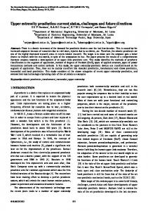
Fig. 2. The three primary module varieties in the first-generation prototype system: a hinge-type actuator (a), a five-connector hub (b), and a battery and communications module (c).
standing challenges in rover design, the problem of righting a rover that has fallen over, by configuring one or more arms with the appropriate geometry to push itself back up.
4. Prototype Hardware We have developed prototype modular robot hardware with an eye towards gaining a greater understanding of the practical issues that will impact the design of modular robotic equipment for use in space. As discussed later, this hardware also serves a dual purpose in supporting near-term terrestrial robotics research. Our modular robots differ from most existing robots in several respects. Most importantly, they are heterogeneous, consisting of modules of several different types each designed to perform a particular simple function. A number of other labs have focused their attention on the problem of self-reconfiguration [3]–[7]. However, many of the advantages of modular robots, such as reusability of hardware for a range of tasks and reduction in the number of spare components required, do not depend on this ability at all, and hardware to support self-reconfiguration can add significantly to module weight, size, cost, and complexity. Thus the modules discussed in this paper were all designed for quick and easy manual reconfiguration, in this case using thumb-screws. We present two generations of prototype hardware. The first generation was a quick and inexpensive design featuring a small number of module types intended to provide some insight into the issues that arise in the design, construction, and use of manuallyreconfigurable modular robots. It has also subsequently
been used as a platform for research in gait optimization and robot arm calibration. The second generation, currently undergoing construction and testing, builds on the lessons of the first and expands the number of module types available.
4.1. First-generation hardware Our first-generation prototype modular robotic system included three module types: a rotational actuator module, a five-connector hub module, and a power and communications module. The design goals were low cost, low mass, and small size. Low mass and size are important so that the behavior of the robot is not limited by motor torque: a snake-like arm, for example, is less useful if it cannot support its own weight. The joints are hinge-type actuated modules, shown in Figure 2(a), similar to those found in existing homogeneous robots such as PolyBot [3] and the NASA Snakebot. For this generation we used inexpensive servomotors of the sort designed for the hobby industry and manufactured in volume. We selected a mediumsized servo with a high torque/mass ratio, and the module scale was chosen to be as small as possible while accommodating that motor. The hub, shown in Figure 2(b), has a novel structure with five connection points arranged to provide a variety of connection angles including 90◦ and 120◦ . With this design it is possible to construct both rectangular and hexagonal lattices for use in assembling larger structural configurations. The hub modules also provide power distribution and communications switching between neighboring modules. The battery and communications module, shown in Figure 2(c), allows the robot to operate fully au-
(a)
(b)
Fig. 3. The first-generation gendered electromechanical connectors (a) and second-generation hermaphroditic connector (b) used in the prototype systems.
tonomously or in a tethered mode, and can be configured with either five or ten AA-size NiMH batteries. Finally, we have also constructed passive “foot modules” which can be installed using the module connector to protect the other modules and to provide a more uniform surface for locomotion. The module connectors, shown in Figure 3(a), were designed for quick and easy manual reconfiguration. They are four-way symmetrical and slide together using alignment pins. Spring-loaded gold-plated contacts establish the electrical connections, and up to four thumbscrews may be used to lock each pair of modules together. There are gendered male and female connectors, but this is not restrictive since each face on each hub may be configured with either a male or female connector. (On the hub shown in Figure 2(b), the top, front, and left faces are configured with male connectors while the bottom and right faces have female connectors.) Achieving low small-quantity module cost and low module mass also guided the selection of the primary module material and manufacturing process. The parts were first printed in an ABS-like plastic using stereolithography and were then plated with a layer of copper followed by a layer of nickel. The resulting parts have essentially the same density as common plastics but considerably greater stiffness, strength, and durability. This is a rapid-prototyping process with virtually zero set-up and tooling costs, making it much more attractive than traditional machining processes for production in research quantities. Moreover, experimentation with minor variations or new module types incurs no additional cost. The resulting 60mm-scale modules are smaller and lighter than those of other reconfigurable modular robots in the research community. The hinge modules
weigh approximately 125gm, and each hub module, with no motor but considerably more structural material, weighs roughly 115gm. The heftier battery module weighs 390gm with the usual ten batteries and 240gm with five. For tethered operation the batteries may be removed entirely, in which case this module weighs only 90gm. The feet are virtually weightless at just over 10gm each. Each powered module is controlled by an Atmel FPSLIC microcontroller/FPGA. The FPGA provides as many communications ports as the module has connectors and interfaces to other on-board hardware such as motors. The microcontroller, a 25MHz AVR core, manages the higher-level communications and control functions. The modules communicate with each other, and optionally with one or more control computers, using a simple ad hoc peer-to-peer network scheme. Any module can send data packets to any other module, and the intermediate modules route the packets accordingly. This permits true distributed control of the modules in addition to the usual master/slave control strategy. We have tested several different robot configurations using these modules, including the classic snakelike arm, robots with multiple arms, and legged robots with three and four legs. A small quadrupedal walking robot is shown in Figure 4.
4.2. Second-generation hardware Our second-generation system has been designed to address several limitations of the first, and is now partially complete. The gendered connectors of the first system, while not strictly limiting, were nevertheless inconvenient, and the new system features the hermaphroditic connector shown in Figure 3(b).
Fig. 4. A quadrupedal walking robot.
electronics and the motor are contained entirely within the hub of the wheel. The second new module type is a digital camera, shown in Figure 5(b). The camera transmits images wirelessly to a controlling computer, thus avoiding the need for a high-bandwidth intermodule communications system. One of the chief limitations of the first-generation system was the low accuracy with which the hobbygrade motors could be controlled. The secondgeneration system is therefore being redesigned with high-precision brushless DC servomotors and backlash-free harmonic gearboxes. The feet modules are also being upgraded with tactile sensing capability based on QTC force sensors. Finally, the remaining electronics are being updated with a larger FPSLIC processor and support for a new higher-voltage power bus.
5. Automated design and optimization
(a)
(b)
Fig. 5. Two new module types introduced in the second-generation prototype system: an actuated wheel (a) and a wide-angle camera (b).
Two entirely new module types have been introduced. The first, shown in Figure 5(a), is an actuated wheel intended for rover-like locomotion at velocities up to approximately a meter per second. The control
To make the most use of a modular robotic system it must be combined with software tools to assist in selecting or designing the best morphology and control structure for each task. While many aspects of this design process will inevitably rely on human intelligence for the foreseeable future, other aspects are amenable to automated design and optimization. It has been shown that, using an evolutionary search algorithm combined with a representation that directly encodes the underlying hierarchical structure of designs, it is possible to search a space of modular robot morphologies and controllers to find candidate designs with desired properties [17]. The problem of premature convergence, which has historically plagued population-based search algorithms in complex spaces, has recently been addressed by using a speciallydesigned population structure [18]. Ultimately, a unified design tool is needed that will give engineers the freedom to quickly develop and test designs in simulation while providing them access to automated design and optimization tools where applicable. We have begun developing a few key elements of such a tool, discussed below.
5.1. Modular robot simulation We have developed a physics-based software simulation environment for modular robots in C++, which allows users to construct robots using a variety of module types and to extend the simulation by adding additional types with compatible connectors. The physical dynamics simulation, based on a modified version
3.5 3
Gait Fitness
2.5 2 1.5 1 0.5 0 0
500
1000
1500
2000
2500
3000
Number of Evaluations
Fig. 6. A simulated modular quadrupedal walking robot used for evolutionary gate optimization.
of the Open Dynamics Engine [19], was designed for high-speed medium-fidelity simulation. Thus it is suitable for use both by engineers wishing to rapidly explore design spaces by hand and also within the evaluation loop of a search or optimization tool. The simulator supports several levels of photo-realism, ranging from simple block representations useful for quick visualization (as shown in Figure 6) to fully rendered images that can be used for simulated closedloop visual control. We have also developed an abstraction layer that allows robot control software to transparently operate both the simulated and real modular robots. This makes it trivial to transfer controller designs from simulation to hardware for testing or use, and also makes it possible to incorporate testing on real hardware into an automated design cycle.
5.2. Quadrupedal gait optimization As an initial test of the simulation and automated optimization system, we optimized the walking gait of the quadrupedal robot shown in Figures 4 and 6. We held the morphology fixed and assumed a periodic gait, with the trajectory of each joint parameterized by the first three Fourier basis coefficients. We evaluated each candidate controller for ten simulated seconds. In order to search for efficient gaits, the fitness was computed as the ratio of the distance travelled to an energy measure derived from the control outputs. We used a steady-state evolutionary search algorithm, similar to simulated annealing but with a population size of four and a mutation rate that decreased over the course of each run. The results of ten runs are shown in Figure 7.
Fig. 7. Ten gait optimization runs. Grey crosses represent evaluated gaits, and black lines indicate the best found so far in each run.
Seven of the ten runs converged to essentially the same high-performing result, while three experienced premature convergence to sub-optimal gaits. The seven all surpassed earlier efforts at manual optimization. They did so by discovering an unexpected gait which walks “sideways” relative to the originally-imagined direction of travel. Furthermore, this somewhat unintuitive gait eliminates the need for four of the eight actuators. In order to be sure that the gait was not taking advantage of some unrealistic property of the simulator, we transferred the gait to the real modular robot, where it performed as advertised.
6. Modular robots in the research lab Robotics is playing an ever-increasing role in educational, industrial, and governmental research labs as well as in the classroom. Many such labs work with a variety of robot morphologies, including rovers, legged robots, manipulator arms, and collaborative robot teams. However, research budgets are often small, and hardware budgets are often smaller. This can constrain the range of morphologies with which a given lab can experiment, and may limit the ability of the robotics community as a whole to explore new morphologies that are not already commercially available. Many educational institutions have attempted to work around this by developing curricula based on LEGO components or other toy-grade modular design kits, but these have well-known limitations. Heterogeneous modular robots, with their fundamentally open-ended morphological range, have the potential to alleviate this problem. A system of modules optimized for low cost could provide an extremely
versatile research platform to researchers wishing to go beyond the standard rover and arm morphologies without investing in custom hardware. In this domain, manual reconfiguration of the sort used in our modules as discussed above would be entirely acceptable. Because all morphologies are derived from a relatively small number of module types, the manufacturing efficiencies associated with mass production promise to drive the price down even further.
7. Conclusion Autonomous robotic systems are critical to achieving sustainability and reliability in NASA’s exploration mission. The current monolithic design approach to robotics offers little room for reuse, adaptation, or maintenance on long-duration or open-ended missions. Adopting a modular design could address these needs, by allowing a single system mass to be reconfigured to suit each task and by reducing the number of spare parts required to achieve redundancy. However, there are many challenges to the scalability, reliability, and usability of such a system that a must be addressed before it could be put to use outside the laboratory. We have presented initial prototype hardware, intended as a platform for beginning to address those challenges. Though this hardware is still far from being immediately useful in a space mission context, its versatility and usability is steadily increasing and we believe it may have immediate applications in the robotics research setting. Each module implements a single core function, reducing individual module complexity and cost and allowing a robotic system to be tailored as needed by including special-purpose modules. By designing for a rapid-prototyping manufacturing technology, it is easy and inexpensive to add new module types when the existing types are insufficient or to make incremental changes between manufacturing runs. Finally, we have described the first components of an automated design and optimization system for modular robots, including a modular robot simulator and an evolutionary controller optimization tool. We have presented the results of applying this system to the optimization of a walking gait, and discussed how the system was even able to outperform the human engineer. As the capabilities of both the robots themselves and automated design tools grow, we expect such tools to be of increasing importance in the use of modular robots.
References [1] K. H. Wurst, “The conception and construction of a modular robot system,” in Proc. JSME 16th Int. Symp. Industrial Robotics (ISIR), 1986, pp. 37–44. [2] M. Yim, “Locomotion with a unit modular reconfigurable robot,” Ph.D. dissertation, Stanford Univ., 1994. [3] M. Yim, Y. Zhang, K. Roufas, D. Duff, and C. Eldershaw, “Connecting and disconnecting for chain self-reconfiguration with PolyBot,” IEEE/ASME Trans. Mechatron., vol. 7, no. 4, pp. 442–451, Dec. 2003. [4] V. Zykov, E. Mytilinaios, B. Adams, and H. Lipson, “Selfreproducing machines,” Nature, vol. 435, no. 7038, pp. 163– 164, 2005. [5] K. Kotay, D. Rus, M. Vona, and C. McGray, “The selfreconfiguring robotic molecule,” in Proc. 1998 IEEE Int. Conf. Robot. Automat., Leuven, Belgium, May 1998, pp. 424–431. [6] D. Rus and M. Vona, “Crystalline robots: Self-reconfiguration with compressible unit modules,” Autonomous Robots, vol. 10, no. 1, pp. 107–124, January 2001. [7] J. W. Suh, S. B. Homans, and M. Yim, “Telecubes: Mechanical design of a module for self-reconfigurable robotics,” in Proc. IEEE Int. Conf. Robot. Automat., vol. 4, 2002, pp. 4095–4101. [8] M. Yim, D. Duff, and K. D. Roufas, “PolyBot: A modular reconfigurable robot,” in Proc. 2000 IEEE Int. Conf. Robot. Automat., vol. 1, San Francisco, CA, 2000, pp. 514–520. [9] C. J. Paredis, H. B. Brosn, and P. K. Khosla, “A rapdily deployable manipulator system,” in Proc. 1996 IEEE Int. Conf. Robot. Automat., Minneapolis, MN, April 1996, pp. 1434– 1439. [10] L. Pedersen, D. Kortenkamp, D. Wettergreen, and I. Nourbakhsh, “Space robotics technology assessment report,” NASA Exploration Team (NEXT), Tech. Rep., December 2002. [11] M. Yim, K. Roufas, D. Duff, Y. Zhang, C. Eldershaw, and S. Homans, “Modular reconfigurable robots in space applications,” Autonomous Robots, vol. 14, no. 2-3, pp. 225–237, March 2003. [12] W. Doggett, “Robotic assembly of truss structures for space systems and future research plans,” in Proc. 2002 IEEE Aerospace Conf., Big Sky, MT, 2002. [13] S. M. Jones, H. A. Aldridge, and S. L. Vazquez, “Wrist camera orientation for effective orbital replaceable unit (ORU) changeout,” NASA, Technical Report TM-4776, 1997. [14] D. S. Portree and R. C. Trevino, Walking to Olympus: An EVA Chronology, ser. Monographs in Aerospace History. Washington, D.C.: NASA, 1997, vol. 7. [15] W. Bluethmann, R. Ambrose, M. Diftler, S. Askew, E. Huber, M. Ooza, F. Rehnmark, C. Lovchik, and D. Magruder, “Robonaut: A robot designed to work with humans in space,” Autonomous Robots, vol. 14, pp. 179–197, 2003. [16] M. M. Cohen, “Mobile lunar and planetary bases,” in Proc. 2003 AIAA Space Conference, San Diego, CA, September 2003. [17] G. S. Hornby, H. Lipson, and J. B. Pollack, “Generative representations for the automated design of modular physical robots,” IEEE Trans. Robot. Automat., vol. 19, no. 4, pp. 703– 719, August 2003. [18] G. S. Hornby, “ALPS: The age-layered population structure for reducing the problem of premature convergence,” in Proc. 2006 Genetic and Evolutionary Computation Conf., July 2006, forthcoming. [19] R. Smith. Open Dynamics Engine (ODE). [Online]. Available: http://www.ode.org/